Instruction Manual
Page 3
... power cable from attempting to prevent erroneous indications. DO NOT use . Pat. R CAUTION! AVOID placing the receiver against continuous high volume operation. The receiver warranty does not cover any cooling vents on top of time. This may overheat the receiver. cohol when cleaning the IC-R9500, as benzine or al- Turn [I/O] switch (on the rear panel. ABOUT APCO PROJECT 25 This device made under license...
... power cable from attempting to prevent erroneous indications. DO NOT use . Pat. R CAUTION! AVOID placing the receiver against continuous high volume operation. The receiver warranty does not cover any cooling vents on top of time. This may overheat the receiver. cohol when cleaning the IC-R9500, as benzine or al- Turn [I/O] switch (on the rear panel. ABOUT APCO PROJECT 25 This device made under license...
Instruction Manual
Page 7
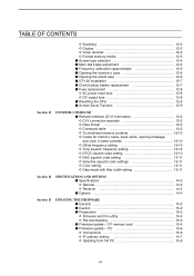
...; Frequency transferring 7-5 D Transferring in VFO mode 7-5 D Transferring in memory mode 7-5 ■ Memory names 7-6 D Editing (programming) memory names 7-6 ■ Memory clearing 7-6 ■ Memory list screen 7-7 D Selecting a memory channel using the memory list screen ...... 7-7 D Confirming programmed memory channels 7-7 D Memory bank set 7-8 D Editing memory channel 7-9 SCANS ■ Scan types 8-2 ■ Preparation 8-3 ■ Voice squelch control function 8-3 ■ Scan set mode 8-4 ■ Priority scan 8-5 D Setting 8-5 D Priority scan operation 8-5 ■...
...; Frequency transferring 7-5 D Transferring in VFO mode 7-5 D Transferring in memory mode 7-5 ■ Memory names 7-6 D Editing (programming) memory names 7-6 ■ Memory clearing 7-6 ■ Memory list screen 7-7 D Selecting a memory channel using the memory list screen ...... 7-7 D Confirming programmed memory channels 7-7 D Memory bank set 7-8 D Editing memory channel 7-9 SCANS ■ Scan types 8-2 ■ Preparation 8-3 ■ Voice squelch control function 8-3 ■ Scan set mode 8-4 ■ Priority scan 8-5 D Setting 8-5 D Priority scan operation 8-5 ■...
Instruction Manual
Page 8
... D Mode select memory scan operation 8-14 ■ Skip scan 8-15 D Specifying skip channels 8-15 D Programming skip frequencies (for programming scan) ......... 8-15 D Skip scan setting 8-15 ■ Tone scan 8-16 ■ Scan resume condition 8-17 ■ Scan speed 8-18 ■ Scan delay 8-18 Section 9 OTHER FUNCTIONS ■ Voice synthesizer operation 9-2 ■ Lock function 9-2 D Dial lock function 9-2 D Panel lock function 9-2 ■ Dial click function 9-3 ■ Antenna selection 9-3 Section 10 CLOCK AND TIMERS ■ Time set mode...
... D Mode select memory scan operation 8-14 ■ Skip scan 8-15 D Specifying skip channels 8-15 D Programming skip frequencies (for programming scan) ......... 8-15 D Skip scan setting 8-15 ■ Tone scan 8-16 ■ Scan resume condition 8-17 ■ Scan speed 8-18 ■ Scan delay 8-18 Section 9 OTHER FUNCTIONS ■ Voice synthesizer operation 9-2 ■ Lock function 9-2 D Dial lock function 9-2 D Panel lock function 9-2 ■ Dial click function 9-3 ■ Antenna selection 9-3 Section 10 CLOCK AND TIMERS ■ Time set mode...
Instruction Manual
Page 9
...-3 D Display 12-3 D Voice recorder 12-3 D Format memory media 12-3 ■ Screen type selection 12-4 ■ Main dial brake adjustment 12-4 ■ Frequency calibration (approximate 12-5 ■ Opening the receiver's case 12-6 ■ Opening the shield case 12-6 ■ UT-122 installation 12-7 ■ Clock backup battery replacement 12-7 ■ Fuse replacement 12-8 D AC power input fuse 12-8 D DC output fuse 12-8 ■ Resetting...
...-3 D Display 12-3 D Voice recorder 12-3 D Format memory media 12-3 ■ Screen type selection 12-4 ■ Main dial brake adjustment 12-4 ■ Frequency calibration (approximate 12-5 ■ Opening the receiver's case 12-6 ■ Opening the shield case 12-6 ■ UT-122 installation 12-7 ■ Clock backup battery replacement 12-7 ■ Fuse replacement 12-8 D AC power input fuse 12-8 D DC output fuse 12-8 ■ Resetting...
Instruction Manual
Page 13
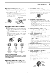
... Noise squelch Squelch threshold Squelch is the notch function? The notch function eliminates unwanted CW or AM carrier tones while preserving the desired voice signal. The DSP circuit automatically adjusts the notch frequency to reject interference. Slow Fast !2 AGC SWITCH [AGC VR/OFF] (p. 5-10) ➥ Push to toggle [AGC] control usage ON or OFF. • Use [AGC] control to set the AGC time...
... Noise squelch Squelch threshold Squelch is the notch function? The notch function eliminates unwanted CW or AM carrier tones while preserving the desired voice signal. The DSP circuit automatically adjusts the notch frequency to reject interference. Slow Fast !2 AGC SWITCH [AGC VR/OFF] (p. 5-10) ➥ Push to toggle [AGC] control usage ON or OFF. • Use [AGC] control to set the AGC time...
Instruction Manual
Page 14
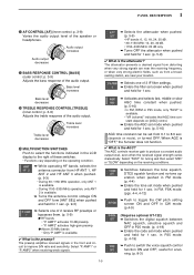
... set mode when pushed and held for 1 sec. !8 AUDIO PEAK FILTER/TWIN PEAK FILTER SWITCH [APF/TPF] ➥ Push to turn the audio peak filter ON or OFF during CW mode operation. (p. 4-9) ➥ Push to select the APF passband width from the DSP unit and does not indicate a malfunction. p. 5-16) Adjusts the DSP noise reduction level when noise reduction is activated. !7 NOISE BLANKER SWITCH...
... set mode when pushed and held for 1 sec. !8 AUDIO PEAK FILTER/TWIN PEAK FILTER SWITCH [APF/TPF] ➥ Push to turn the audio peak filter ON or OFF during CW mode operation. (p. 4-9) ➥ Push to select the APF passband width from the DSP unit and does not indicate a malfunction. p. 5-16) Adjusts the DSP noise reduction level when noise reduction is activated. !7 NOISE BLANKER SWITCH...
Instruction Manual
Page 15
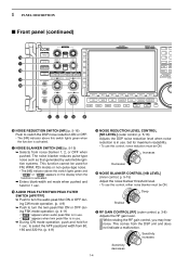
... the audio output. AMP2" activates high-gain preamp. ● Above 30 MHz bands • Only "P. The preamp amplifies received signals in the LCD display to toggle the CW pitch setting screen ON and OFF in CW mode. (p.4-9) (Requires optional UT-122) ➥ Switches the digital squelch between the tone squelch, DTCS squelch function and no-tone operation when pushed in FM mode. (p. 4-4) ➥ Enters the tone set mode when...
... the audio output. AMP2" activates high-gain preamp. ● Above 30 MHz bands • Only "P. The preamp amplifies received signals in the LCD display to toggle the CW pitch setting screen ON and OFF in CW mode. (p.4-9) (Requires optional UT-122) ➥ Switches the digital squelch between the tone squelch, DTCS squelch function and no-tone operation when pushed in FM mode. (p. 4-4) ➥ Enters the tone set mode when...
Instruction Manual
Page 16
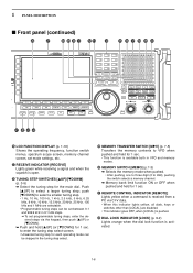
... each operating mode can be set between 0.1 and 999.9 kHz in 0.1 kHz steps. ➠ To set mode settings, etc. @7 RECEIVE INDICATOR [RECEIVE] Lights green while receiving a signal and when the squelch is available both in the tuning step select. @9 MEMORY TRANSFER SWITCH [M≈V] (p. 7-5) Transfers the memory contents to VFO when pushed and held for 1 sec. • This function is open. @8 TUNING STEP SWITCHES [▲...
... each operating mode can be set between 0.1 and 999.9 kHz in 0.1 kHz steps. ➠ To set mode settings, etc. @7 RECEIVE INDICATOR [RECEIVE] Lights green while receiving a signal and when the squelch is available both in the tuning step select. @9 MEMORY TRANSFER SWITCH [M≈V] (p. 7-5) Transfers the memory contents to VFO when pushed and held for 1 sec. • This function is open. @8 TUNING STEP SWITCHES [▲...
Instruction Manual
Page 21
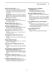
... [S/P DIF OUT] (p. 2-7) Connects external equipment that supports S/P DIF output. @3 HF ANTENNA CONNECTOR 3/ANTENNA CONNECTOR 1 [ANT 1/HF ANT 3] (p. 2-5) Accepts a 50 Ω antenna with a Type-N connector. CAUTION: Always use the correct fuse for internal AC power supply protection. Cuts off the AC input when over-current occurs. Covers the 1150-3335 MHz frequency range. @6 EXTERNAL DISPLAY TERMINAL [EXT-DISPLAY] (p. 2-10) Connects to a PC using a D-sub 9-pin RS-232C cable.
... [S/P DIF OUT] (p. 2-7) Connects external equipment that supports S/P DIF output. @3 HF ANTENNA CONNECTOR 3/ANTENNA CONNECTOR 1 [ANT 1/HF ANT 3] (p. 2-5) Accepts a 50 Ω antenna with a Type-N connector. CAUTION: Always use the correct fuse for internal AC power supply protection. Cuts off the AC input when over-current occurs. Covers the 1150-3335 MHz frequency range. @6 EXTERNAL DISPLAY TERMINAL [EXT-DISPLAY] (p. 2-10) Connects to a PC using a D-sub 9-pin RS-232C cable.
Instruction Manual
Page 26
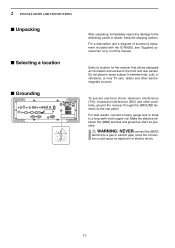
... and rear panels. For a description and a diagram of this manual. Do not place in areas subject to extreme heat, cold, or vibrations, or near TV sets, radios and other problems, ground the receiver through the GROUND terminal on p. To prevent electrical shock, television interference (TVI), broadcast interference (BCI) and other electromagnetic sources. 2 INSTALLATION AND CONNECTIONS ■ Unpacking ■ Selecting a location...
... and rear panels. For a description and a diagram of this manual. Do not place in areas subject to extreme heat, cold, or vibrations, or near TV sets, radios and other problems, ground the receiver through the GROUND terminal on p. To prevent electrical shock, television interference (TVI), broadcast interference (BCI) and other electromagnetic sources. 2 INSTALLATION AND CONNECTIONS ■ Unpacking ■ Selecting a location...
Instruction Manual
Page 34
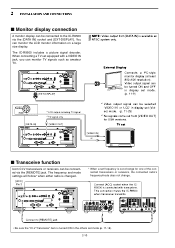
... connection mutes the IC-R9500 when transceiver transmits. When connecting a TV set (Video) mode. (p. 11-25) *2 No signals come out from [DATA IN] is connected with a VIDEO IN jack, you can monitor TV signals such as amateur TV. [EXT-DISPLAY] NOTE: Video output from [VIDEO OUT] for one of -range for USA versions. The frequency and mode settings will follow* when either radio is changed. [ACC] Pin 3 * When a set frequency is turned...
... connection mutes the IC-R9500 when transceiver transmits. When connecting a TV set (Video) mode. (p. 11-25) *2 No signals come out from [DATA IN] is connected with a VIDEO IN jack, you can monitor TV signals such as amateur TV. [EXT-DISPLAY] NOTE: Video output from [VIDEO OUT] for one of -range for USA versions. The frequency and mode settings will follow* when either radio is changed. [ACC] Pin 3 * When a set frequency is turned...
Instruction Manual
Page 38
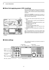
... 3-2 clockwise After resetting the receiver, set mode settings after turning power ON. Then, reset the receiver using the following procedure. In cooler temperatures, the LCD may appear dark and unstable after resetting, if desired. counter clockwise [RF]: Max. counter clockwise [NR LEVEL] : Max. 3 BASIC OPERATIONS ■ When first applying power (CPU resetting) Before first applying power, make sure all programmed contents in memory channels and returns programmed values in...
... 3-2 clockwise After resetting the receiver, set mode settings after turning power ON. Then, reset the receiver using the following procedure. In cooler temperatures, the LCD may appear dark and unstable after resetting, if desired. counter clockwise [RF]: Max. counter clockwise [NR LEVEL] : Max. 3 BASIC OPERATIONS ■ When first applying power (CPU resetting) Before first applying power, make sure all programmed contents in memory channels and returns programmed values in...
Instruction Manual
Page 43
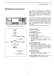
... selected, push and hold [SSB/CW] for 1 sec. 3 BASIC OPERATIONS FM, WFM, AM, Synchronous-AM (S-AM(D)/SAM(U)/S-AM(L)), SSB (USB/LSB), CW, CW reverse (CW-R), FSK, FSK reverse (FSK-R) and DIGITAL (P25*) modes are available in the IC-R9500. to toggle between S-AM(DSB), S-AM(USB) and SAM(LSB).... is automatically selected) and CW. • After SSB or CW is selected, push and hold the switch for 1 sec. Push the switch again to toggle between FSK and FSK reverse mode. • Selecting DIGITAL mode (Requires optional U-122) ➥ Push [DIGITAL] to toggle between S-AM(D), S-AM(U) and SAM(L),...
... selected, push and hold [SSB/CW] for 1 sec. 3 BASIC OPERATIONS FM, WFM, AM, Synchronous-AM (S-AM(D)/SAM(U)/S-AM(L)), SSB (USB/LSB), CW, CW reverse (CW-R), FSK, FSK reverse (FSK-R) and DIGITAL (P25*) modes are available in the IC-R9500. to toggle between S-AM(DSB), S-AM(USB) and SAM(LSB).... is automatically selected) and CW. • After SSB or CW is selected, push and hold the switch for 1 sec. Push the switch again to toggle between FSK and FSK reverse mode. • Selecting DIGITAL mode (Requires optional U-122) ➥ Push [DIGITAL] to toggle between S-AM(D), S-AM(U) and SAM(L),...
Instruction Manual
Page 82
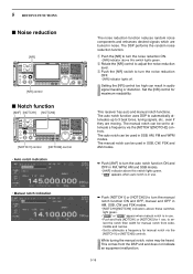
... buried in AM, SSB, CW and FSK modes. • [NOTCH1]/[NOTCH2] indicators above this switch lights green. The auto notch function uses DSP to automatically attenuates up to turn the noise reduction OFF. • [NR] indicator lights off. Set the [NR] control for manual notch via the [NOTCH1]/[NOTCH2] controls. 5 RECEIVE FUNCTIONS ■ Noise reduction [NR] [NR] control ■ Notch function...
... buried in AM, SSB, CW and FSK modes. • [NOTCH1]/[NOTCH2] indicators above this switch lights green. The auto notch function uses DSP to automatically attenuates up to turn the noise reduction OFF. • [NR] indicator lights off. Set the [NR] control for manual notch via the [NOTCH1]/[NOTCH2] controls. 5 RECEIVE FUNCTIONS ■ Noise reduction [NR] [NR] control ■ Notch function...
Instruction Manual
Page 97
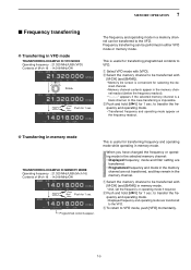
... [M-CH] (and [BANK]). • Memory list screen is impossible. When you have changed the frequency or operating mode in the selected memory channel: • Displayed frequency, mode and filter setting are transferred. • Programmed frequency and mode in the memory channel are transferred to transfer the frequency and operating mode. • Displayed frequency and operating mode are not transferred, and they remain in the memory channel. to the VFO. nel readout (below...
... [M-CH] (and [BANK]). • Memory list screen is impossible. When you have changed the frequency or operating mode in the selected memory channel: • Displayed frequency, mode and filter setting are transferred. • Programmed frequency and mode in the memory channel are transferred to transfer the frequency and operating mode. • Displayed frequency and operating mode are not transferred, and they remain in the memory channel. to the VFO. nel readout (below...
Instruction Manual
Page 105
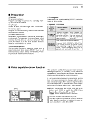
.... SCANS 8 ■ Preparation • Channels For programmed scan: Program scan edge frequencies into scan edge memory channels PxA and PxB. Scan resume ON/OFF must be adjusted by [SPEED] controller. For memory scan: Program 2 or more memory channels as a select memory channel, choose a memory channel, then push [F-3•SELECT] in the scan screen (memory mode) or in the scan screen. For ∂F scan: Set the ∂F span (∂F scan range) in the memory list...
.... SCANS 8 ■ Preparation • Channels For programmed scan: Program scan edge frequencies into scan edge memory channels PxA and PxB. Scan resume ON/OFF must be adjusted by [SPEED] controller. For memory scan: Program 2 or more memory channels as a select memory channel, choose a memory channel, then push [F-3•SELECT] in the scan screen (memory mode) or in the scan screen. For ∂F scan: Set the ∂F span (∂F scan range) in the memory list...
Instruction Manual
Page 118
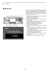
... tone frequency is detected, the tone scan pauses. • The tone frequency is being operated with tone or DTCS squelch function, you can detect subaudible tones or the DTCS code in a received signal. Program into the memory channel to store the tone frequency permanently. • The decoded tone frequency is used for 1 sec. 8 SCANS ■ Tone scan [F-1•Y] [F-2•Z] [F-4•DEF] [F-6•T-SCAN] [TONE] [FM] [EXIT/SET] The receiver can determine the tone frequency or DTCS code necessary to open a squelch...
... tone frequency is detected, the tone scan pauses. • The tone frequency is being operated with tone or DTCS squelch function, you can detect subaudible tones or the DTCS code in a received signal. Program into the memory channel to store the tone frequency permanently. • The decoded tone frequency is used for 1 sec. 8 SCANS ■ Tone scan [F-1•Y] [F-2•Z] [F-4•DEF] [F-6•T-SCAN] [TONE] [FM] [EXIT/SET] The receiver can determine the tone frequency or DTCS code necessary to open a squelch...

Instruction Manual
Page 146
...the CF (Compact Flash) memory card or USB-memory for 1 sec. e Change the following conditions if desired. • File name: z Push [F-4•EDIT] to select file name edit condition. • Push [F-1• DIR/FILE] several times to select the ...file name. to delete the folder. • Push and hold [F-1•DIR/FILE] for 1 sec. to select CF/USB-Memory set mode settings, etc. to making a new...
...the CF (Compact Flash) memory card or USB-memory for 1 sec. e Change the following conditions if desired. • File name: z Push [F-4•EDIT] to select file name edit condition. • Push [F-1• DIR/FILE] several times to select the ...file name. to delete the folder. • Push and hold [F-1•DIR/FILE] for 1 sec. to select CF/USB-Memory set mode settings, etc. to making a new...
Instruction Manual
Page 156
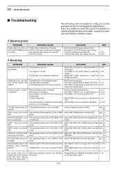
... open the p. 3-8 squelch. • Rotate [RF GAIN] clockwise to reset the function. No sounds come out or • Either the audio tone controls is too decreas- • Rotate [BASS] or [TREBLE] clockwise to obtain p. 3-9 output level is too low. p. 5-11 • Noise blanker is above 30 MHz. 12 MAINTENANCE ■ Troubleshooting The following chart is designed to help you nearest Icom Dealer or Service...
... open the p. 3-8 squelch. • Rotate [RF GAIN] clockwise to reset the function. No sounds come out or • Either the audio tone controls is too decreas- • Rotate [BASS] or [TREBLE] clockwise to obtain p. 3-9 output level is too low. p. 5-11 • Noise blanker is above 30 MHz. 12 MAINTENANCE ■ Troubleshooting The following chart is designed to help you nearest Icom Dealer or Service...
Instruction Manual
Page 188
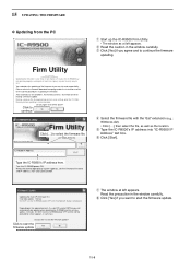
..., Please refer to start the firmware update? Also all of the above? Making a backup file of the firmware at you make a mistake, the IC-R9500 may not operate properly, and repair at left appears. Do you want to the firmware download homepage and/or the instruction manual for the correct procedures in the window carefully. Turn the IC-R9500 power ON. r Select the firmware file with the "dat...
..., Please refer to start the firmware update? Also all of the above? Making a backup file of the firmware at you make a mistake, the IC-R9500 may not operate properly, and repair at left appears. Do you want to the firmware download homepage and/or the instruction manual for the correct procedures in the window carefully. Turn the IC-R9500 power ON. r Select the firmware file with the "dat...


