
Instruction Manual
Page 1
COMMUNICATIONS RECEIVER iR9500 Instruction Manual A-6553H-1EX-q Printed in Japan © 2007 Icom Inc.
COMMUNICATIONS RECEIVER iR9500 Instruction Manual A-6553H-1EX-q Printed in Japan © 2007 Icom Inc.

Instruction Manual
Page 2
...CAUTION NOTE DEFINITION Personal injury, fire hazard or electric shock may occur. Please consult with the relevant Government Department in your IC-R9500. D FEATURES ❍ Ultimate receiver performance: 109 dB wide dynamic range and third-order intercept (IP3) of personal injury, fire or electric shock. This ...." Export regulations can be highly restrictive in relation to fines or penalties. FOREWORD Thank you for the IC-R9500. We hope you to some of Icom Incorporated (Japan) in compliance with Icom's philosophy of choice. Your failure to operate the receiver.
...CAUTION NOTE DEFINITION Personal injury, fire hazard or electric shock may occur. Please consult with the relevant Government Department in your IC-R9500. D FEATURES ❍ Ultimate receiver performance: 109 dB wide dynamic range and third-order intercept (IP3) of personal injury, fire or electric shock. This ...." Export regulations can be highly restrictive in relation to fines or penalties. FOREWORD Thank you for the IC-R9500. We hope you to some of Icom Incorporated (Japan) in compliance with Icom's philosophy of choice. Your failure to operate the receiver.
Instruction Manual
Page 3
...: Changes or modifications to this device, not expressly approved by Icom Inc., could void your ears, reduce the volume or discontinue use by unauthorized internal adjustment. PRECAUTIONS R WARNING! If you will not use the receiver for use chemical agents such as small dark or light spots.... engineer, or disassemble the object code, or in your authority to the receiver. cohol when cleaning the IC-R9500, as possible from attempting to carry, lift or turn over the receiver. AVOID using or storing the receiver in a secure place to rain, snow or any cooling vents on top...
...: Changes or modifications to this device, not expressly approved by Icom Inc., could void your ears, reduce the volume or discontinue use by unauthorized internal adjustment. PRECAUTIONS R WARNING! If you will not use the receiver for use chemical agents such as small dark or light spots.... engineer, or disassemble the object code, or in your authority to the receiver. cohol when cleaning the IC-R9500, as possible from attempting to carry, lift or turn over the receiver. AVOID using or storing the receiver in a secure place to rain, snow or any cooling vents on top...
Instruction Manual
Page 5
... gain adjustment 3-8 ■ Squelch level adjustment 3-8 ■ Audio tone adjustment 3-9 D Treble level adjustment 3-9 D Bass level adjustment 3-9 ■ Meter indication selection 3-10 D Meter type selection 3-10 RECEIVE MODES ■ Operating FM 4-2 D Convenient functions for FM 4-2 ■ Duplex operation 4-3 D Offset frequency setting 4-3 iv
... gain adjustment 3-8 ■ Squelch level adjustment 3-8 ■ Audio tone adjustment 3-9 D Treble level adjustment 3-9 D Bass level adjustment 3-9 ■ Meter indication selection 3-10 D Meter type selection 3-10 RECEIVE MODES ■ Operating FM 4-2 D Convenient functions for FM 4-2 ■ Duplex operation 4-3 D Offset frequency setting 4-3 iv
Instruction Manual
Page 6
... D Convenient functions for P25 4-18 ■ Digital squelch operation 4-19 ■ TV channel operation (except for USA versions 4-20 D Convenient functions for TV operation 4-20 RECEIVE FUNCTIONS ■ Spectrum scope screen 5-2 D Center mode 5-2 D Fix mode 5-3 D Peak marker function 5-4 D Wide band-pass filter selection 5-5 D Wide band scope function 5-5 D Mini scope screen indication...
... D Convenient functions for P25 4-18 ■ Digital squelch operation 4-19 ■ TV channel operation (except for USA versions 4-20 D Convenient functions for TV operation 4-20 RECEIVE FUNCTIONS ■ Spectrum scope screen 5-2 D Center mode 5-2 D Fix mode 5-3 D Peak marker function 5-4 D Wide band-pass filter selection 5-5 D Wide band scope function 5-5 D Mini scope screen indication...
Instruction Manual
Page 7
...; Noise reduction 5-16 ■ Notch function 5-16 ■ Autotune function 5-17 ■ AFC function 5-17 VOICE RECORDER FUNCTIONS ■ About digital voice recorder 6-2 ■ Recording a received audio 6-3 D Regular recording 6-3 ■ Playing the recorded audio 6-4 D Regular playing 6-4 ■ Erasing the recorded contents 6-4 ■ Selecting the CF memory card or USB-Memory 6-4 ■...
...; Noise reduction 5-16 ■ Notch function 5-16 ■ Autotune function 5-17 ■ AFC function 5-17 VOICE RECORDER FUNCTIONS ■ About digital voice recorder 6-2 ■ Recording a received audio 6-3 D Regular recording 6-3 ■ Playing the recorded audio 6-4 D Regular playing 6-4 ■ Erasing the recorded contents 6-4 ■ Selecting the CF memory card or USB-Memory 6-4 ■...
Instruction Manual
Page 8
... card or USB-Memory 11-23 ■ Display set (Video) mode 11-24 ■ LCD set mode 11-26 Section 12 MAINTENANCE ■ Troubleshooting 12-2 D Receiver power 12-2 D Receiving 12-2 vii
... card or USB-Memory 11-23 ■ Display set (Video) mode 11-24 ■ LCD set mode 11-26 Section 12 MAINTENANCE ■ Troubleshooting 12-2 D Receiver power 12-2 D Receiving 12-2 vii
Instruction Manual
Page 9
... 12-3 ■ Screen type selection 12-4 ■ Main dial brake adjustment 12-4 ■ Frequency calibration (approximate 12-5 ■ Opening the receiver's case 12-6 ■ Opening the shield case 12-6 ■ UT-122 installation 12-7 ■ Clock backup battery replacement 12-7 ■...setting 13-11 D Data mode with filter width setting 13-11 Section 14 SPECIFICATIONS AND OPTIONS ■ Specifications 14-2 D General 14-2 D Receiver 14-3 ■ Options 14-4 Section 15 UPDATING THE FIRMWARE ■ General 15-2 ■ Caution 15-2 ■ Preparation 15-3 D Firmware...
... 12-3 ■ Screen type selection 12-4 ■ Main dial brake adjustment 12-4 ■ Frequency calibration (approximate 12-5 ■ Opening the receiver's case 12-6 ■ Opening the shield case 12-6 ■ UT-122 installation 12-7 ■ Clock backup battery replacement 12-7 ■...setting 13-11 D Data mode with filter width setting 13-11 Section 14 SPECIFICATIONS AND OPTIONS ■ Specifications 14-2 D General 14-2 D Receiver 14-3 ■ Options 14-4 Section 15 UPDATING THE FIRMWARE ■ General 15-2 ■ Caution 15-2 ■ Preparation 15-3 D Firmware...
Instruction Manual
Page 12
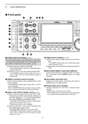
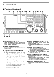
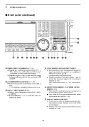
... OFF. • The [POWER] indicator lights orange when the receiver is OFF when the internal power supply is switched ON. t RECORDER REMOTE JACK [REC REMOTE] Controls the operation of a tape recorder for 1 sec. u HEADPHONE JACK [.... • The [TIMER] indicator above this switch lights green when the timer is also available. ➥ Push and hold for recording. Connect to turn the receiver power ON. • The [POWER] indicator above this switch lights green and the display turns OFF when the sleep function is located on p. 11-10...
... OFF. • The [POWER] indicator lights orange when the receiver is OFF when the internal power supply is switched ON. t RECORDER REMOTE JACK [REC REMOTE] Controls the operation of a tape recorder for 1 sec. u HEADPHONE JACK [.... • The [TIMER] indicator above this switch lights green when the timer is also available. ➥ Push and hold for recording. Connect to turn the receiver power ON. • The [POWER] indicator above this switch lights green and the display turns OFF when the sleep function is located on p. 11-10...
Instruction Manual
Page 13
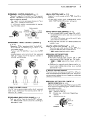
Shallow Deep Noise squelch Squelch threshold Squelch is the PBT control? to 5100 Hz NOTCH1 NOTCH2 Lower frequency Higher frequency 1-3 This receiver uses the DSP circuit for the PBT function. !0 PBT CLEAR SWITCH [PBT CLEAR] (p. 5-11) Push and hold [PBT CLEAR...PANEL DESCRIPTION i SQUELCH CONTROL [SQUELCH] (p. 3-8) Adjusts the squelch threshold level. The squelch disables output from the speaker (closed condition) when no signal is received. • The squelch control is particularly effective for 1 sec. !3 AUTO NOTCH SWITCH [ANF] (p. 5-16) ➥ Turns the auto notch function ON...
Shallow Deep Noise squelch Squelch threshold Squelch is the PBT control? to 5100 Hz NOTCH1 NOTCH2 Lower frequency Higher frequency 1-3 This receiver uses the DSP circuit for the PBT function. !0 PBT CLEAR SWITCH [PBT CLEAR] (p. 5-11) Push and hold [PBT CLEAR...PANEL DESCRIPTION i SQUELCH CONTROL [SQUELCH] (p. 3-8) Adjusts the squelch threshold level. The squelch disables output from the speaker (closed condition) when no signal is received. • The squelch control is particularly effective for 1 sec. !3 AUTO NOTCH SWITCH [ANF] (p. 5-16) ➥ Turns the auto notch function ON...
Instruction Manual
Page 15
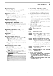
... • During 30-1150 MHz operation, only ANT 1 is available. • During 1150-3335 MHz operation, only ANT 2 is the attenuator? The preamp amplifies received signals in P25 mode. (p. 4-19) ➥ Push to 8.0 sec. (depends on [AGC] control. ➥ Enters the AGC set mode when pushed and held... for 1 sec. (p. 5-10) AGC time constant can be set mode when pushed and held for scanning. (p. 8-3) 1-5 AMP2" when receiving weak signals. ➥ Activates and selects fast, middle or slow AGC time constant when pushed. (p. 5-10) • In FM, WFM or P25 mode...
... • During 30-1150 MHz operation, only ANT 1 is available. • During 1150-3335 MHz operation, only ANT 2 is the attenuator? The preamp amplifies received signals in P25 mode. (p. 4-19) ➥ Push to 8.0 sec. (depends on [AGC] control. ➥ Enters the AGC set mode when pushed and held... for 1 sec. (p. 5-10) AGC time constant can be set mode when pushed and held for scanning. (p. 8-3) 1-5 AMP2" when receiving weak signals. ➥ Activates and selects fast, middle or slow AGC time constant when pushed. (p. 5-10) • In FM, WFM or P25 mode...
Instruction Manual
Page 16
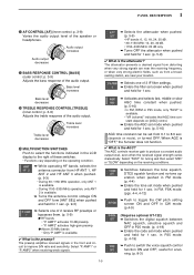
...when pushed and held for 1 sec. • This function is available both in 0.1 kHz steps. ➠ To set mode settings, etc. @7 RECEIVE INDICATOR [RECEIVE] Lights green while receiving a signal and when the squelch is open. @8 TUNING STEP SWITCHES [▲UP]/[▼DOWM] (p. 3-5) ➥ Select the tuning step for 1 sec...; Memory bank limit function ON or OFF when pushed and held for 1 sec. #1 REMOTE CONTROL INDICATOR [REMOTE] Lights yellow when a command is received from a PC via the keypad, then push [YUP] or [ZDOWN]. ➥ Push and hold [▲UP] (or [▼DOWN]) for the main ...
...when pushed and held for 1 sec. • This function is available both in 0.1 kHz steps. ➠ To set mode settings, etc. @7 RECEIVE INDICATOR [RECEIVE] Lights green while receiving a signal and when the squelch is open. @8 TUNING STEP SWITCHES [▲UP]/[▼DOWM] (p. 3-5) ➥ Select the tuning step for 1 sec...; Memory bank limit function ON or OFF when pushed and held for 1 sec. #1 REMOTE CONTROL INDICATOR [REMOTE] Lights yellow when a command is received from a PC via the keypad, then push [YUP] or [ZDOWN]. ➥ Push and hold [▲UP] (or [▼DOWN]) for the main ...
Instruction Manual
Page 17
... the desired mode. (p. 3-7) • Announces selected mode via the speech synthesizer. (p. 11-11) ➥ Selects FM mode. When receiving a weak signal, or receiving a signal with interference, the automatic tuning function may tune the receiver to an undesired signal. $1 LCD FUNCTION SWITCHES [F-1]-[F-7] Push to select the function indicated in CW mode. ➥ Selects FSK...
... the desired mode. (p. 3-7) • Announces selected mode via the speech synthesizer. (p. 11-11) ➥ Selects FM mode. When receiving a weak signal, or receiving a signal with interference, the automatic tuning function may tune the receiver to an undesired signal. $1 LCD FUNCTION SWITCHES [F-1]-[F-7] Push to select the function indicated in CW mode. ➥ Selects FSK...
Instruction Manual
Page 18
... [DUP] (p. 4-3) ➥ Push to select the duplex function (DUP-, DUP+ and OFF). ➥ Push and hold for 1 sec. to record the received signal until recording is ON, LEDs and LCD backlight become dim according to the preset setting. ➥ Push and hold for 1 sec. Push and hold... for 1 sec. Push momentarily to record the signal received for 1 sec. 1-8 to stop recording. $9 SHORT VOICE MEMORY PLAY BACK SWITCH [PLAY] (p. 6-5) ➥ Plays back the audio previously recorded during the...
... [DUP] (p. 4-3) ➥ Push to select the duplex function (DUP-, DUP+ and OFF). ➥ Push and hold for 1 sec. to record the received signal until recording is ON, LEDs and LCD backlight become dim according to the preset setting. ➥ Push and hold for 1 sec. Push and hold... for 1 sec. Push momentarily to record the signal received for 1 sec. 1-8 to stop recording. $9 SHORT VOICE MEMORY PLAY BACK SWITCH [PLAY] (p. 6-5) ➥ Plays back the audio previously recorded during the...

Instruction Manual
Page 19
... and hold to open the squelch manually. • The [MONI] indicator appears on the display. • While pushing and holding this switch, release any other receiving functions such as the noise blanker or ANF. • While in a duplex operation, monitor the shifted frequency. %2 MAIN DIAL Changes the displayed frequency, selects set...
... and hold to open the squelch manually. • The [MONI] indicator appears on the display. • While pushing and holding this switch, release any other receiving functions such as the noise blanker or ANF. • While in a duplex operation, monitor the shifted frequency. %2 MAIN DIAL Changes the displayed frequency, selects set...
Instruction Manual
Page 20
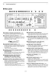
...-10dBm] Inputs/outputs a 10 MHz reference signal. y SPEECH OUTPUT JACK [SPEECH OUT] (p. 2-9) Outputs an operating frequency, mode, S-meter indication and time with WFM mode are received. Connected in ACC set for external preamplifier or antenna selector, etc. 1 PANEL DESCRIPTION ■ Rear panel q w e r t y u i o !0 !1 !2 !3 !4 !5 !6 !7 @9 @8 @7 @6 @5 @4 @3 @2 @1 @0 !9 !8 q EXTERNAL SPEAKER JACK [EXT-SP] (p. 2-6) Connects an external speaker...
...-10dBm] Inputs/outputs a 10 MHz reference signal. y SPEECH OUTPUT JACK [SPEECH OUT] (p. 2-9) Outputs an operating frequency, mode, S-meter indication and time with WFM mode are received. Connected in ACC set for external preamplifier or antenna selector, etc. 1 PANEL DESCRIPTION ■ Rear panel q w e r t y u i o !0 !1 !2 !3 !4 !5 !6 !7 @9 @8 @7 @6 @5 @4 @3 @2 @1 @0 !9 !8 q EXTERNAL SPEAKER JACK [EXT-SP] (p. 2-6) Connects an external speaker...
Instruction Manual
Page 21
... EXTERNAL DISPLAY TERMINAL [EXT-DISPLAY] (p. 2-10) Connects to a PC through a LAN (Local Area Network). @5 ANTENNA CONNECTOR 2 [ANT 2] (p. 2-5) Accepts a 50 Ω antenna with another Icom CI-V transceiver or receiver. @9 DATA SOCKET [DATA IN] (pgs. 2-10, 2-12) Outputs LCD monitor signals (NTSC system). 1-11 Covers the HF bands and 30-1150 MHz frequency range...versions) for AC input power. CAUTION: Always use the correct fuse for internal AC power supply protection. Using a fuse rated for external control of the IC-R9500 without the optional CT-17, or the FSK decoded signal output.
... EXTERNAL DISPLAY TERMINAL [EXT-DISPLAY] (p. 2-10) Connects to a PC through a LAN (Local Area Network). @5 ANTENNA CONNECTOR 2 [ANT 2] (p. 2-5) Accepts a 50 Ω antenna with another Icom CI-V transceiver or receiver. @9 DATA SOCKET [DATA IN] (pgs. 2-10, 2-12) Outputs LCD monitor signals (NTSC system). 1-11 Covers the HF bands and 30-1150 MHz frequency range...versions) for AC input power. CAUTION: Always use the correct fuse for internal AC power supply protection. Using a fuse rated for external control of the IC-R9500 without the optional CT-17, or the FSK decoded signal output.
Instruction Manual
Page 22
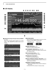
... IF filter number. 1 PANEL DESCRIPTION ■ LCD display q w e r t y u i o @9 @8 @7 @6 @5 @4 @3 @2 @1 @0 !9 !8 !7 !6 !5 !4 !3 !2 !1 !0 q RSSI (Received Signal Strength Indication) METER (p. 3-10) Shows the received signal strength. Four meter types, S, dBµ, dBµ(EMF) and dBm meters are selectable. • S-meter w CENTER METER Shows that the... received signal is set as a select memory channel. i MEMORY CHANNEL READOUTS ➥ Shows the selected memory channel contents ...
... IF filter number. 1 PANEL DESCRIPTION ■ LCD display q w e r t y u i o @9 @8 @7 @6 @5 @4 @3 @2 @1 @0 !9 !8 !7 !6 !5 !4 !3 !2 !1 !0 q RSSI (Received Signal Strength Indication) METER (p. 3-10) Shows the received signal strength. Four meter types, S, dBµ, dBµ(EMF) and dBm meters are selectable. • S-meter w CENTER METER Shows that the... received signal is set as a select memory channel. i MEMORY CHANNEL READOUTS ➥ Shows the selected memory channel contents ...

Instruction Manual
Page 25
Always have two people available to carry, lift or turn over the receiver. 2-1 INSTALLATION AND CONNECTIONS Section 2 ■ Unpacking 2-2 ■ Selecting a location 2-2 ■ Grounding 2-2 ■ Antenna connection 2-3 ■ TV jumper cable connection (except for USA versions 2-4 ■ Carrying ... and frequency 2-9 ■ Monitor display connection 2-10 ■ Transceive function 2-10 ■ FSK and AFSK (SSTV) connections 2-11 ■ Accessory connector information 2-12 CAUTION!: The receiver weighs approx. 20 kg (44 lb).
Always have two people available to carry, lift or turn over the receiver. 2-1 INSTALLATION AND CONNECTIONS Section 2 ■ Unpacking 2-2 ■ Selecting a location 2-2 ■ Grounding 2-2 ■ Antenna connection 2-3 ■ TV jumper cable connection (except for USA versions 2-4 ■ Carrying ... and frequency 2-9 ■ Monitor display connection 2-10 ■ Transceive function 2-10 ■ FSK and AFSK (SSTV) connections 2-11 ■ Accessory connector information 2-12 CAUTION!: The receiver weighs approx. 20 kg (44 lb).
Instruction Manual
Page 26
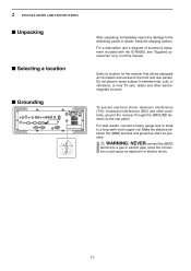
...manual. iii of accessory equipment included with the IC-R9500, see 'Supplied accessories' on the rear panel. 2 INSTALLATION AND CONNECTIONS ■ Unpacking ■ Selecting a location ■ Grounding After unpacking, immediately report any damage to the front and rear panels. Select a location for the receiver that allows adequate air circulation and access to the... as possible. Do not place in areas subject to extreme heat, cold, or vibrations, or near TV sets, radios and other problems, ground the receiver through the GROUND terminal on p. Keep the shipping cartons.
...manual. iii of accessory equipment included with the IC-R9500, see 'Supplied accessories' on the rear panel. 2 INSTALLATION AND CONNECTIONS ■ Unpacking ■ Selecting a location ■ Grounding After unpacking, immediately report any damage to the front and rear panels. Select a location for the receiver that allows adequate air circulation and access to the... as possible. Do not place in areas subject to extreme heat, cold, or vibrations, or near TV sets, radios and other problems, ground the receiver through the GROUND terminal on p. Keep the shipping cartons.

