Instruction Manual
Page 3
... IMBE™ voice coding technology embodied in your authority to prevent erroneous indications. U.S. ii cohol when cleaning the IC-R9500, as possible from attempting to avoid inadvertent use . During maritime mobile operation, keep the receiver as far away as they can damage the receiver's surfaces. ...Turn [I/O] switch (on the top, rear or bottom of this device, not expressly approved by Icom Inc., could void your ears, reduce the volume or discontinue use by unauthorized internal adjustment. R CAUTION! P25 digital mode is available when the optional UT-122...
... IMBE™ voice coding technology embodied in your authority to prevent erroneous indications. U.S. ii cohol when cleaning the IC-R9500, as possible from attempting to avoid inadvertent use . During maritime mobile operation, keep the receiver as far away as they can damage the receiver's surfaces. ...Turn [I/O] switch (on the top, rear or bottom of this device, not expressly approved by Icom Inc., could void your ears, reduce the volume or discontinue use by unauthorized internal adjustment. R CAUTION! P25 digital mode is available when the optional UT-122...
Instruction Manual
Page 4
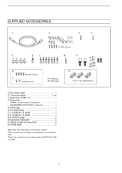
... 1 u 2-conductor 1⁄8″ plugs 7 i 3-conductor 1⁄8″ plugs 1 o 8 pin ACC plugs 2 !0 Screws for side plate 4 !1 Hiding screws for installation details) iii dles. ‡These are used when connecting cables to [DATA IN], [LAN] or [USB]. !2 (see p. 2-7 for screw hole 2 !2 Ferrite bead 3 *May differ from that shown according to version. †These...
... 1 u 2-conductor 1⁄8″ plugs 7 i 3-conductor 1⁄8″ plugs 1 o 8 pin ACC plugs 2 !0 Screws for side plate 4 !1 Hiding screws for installation details) iii dles. ‡These are used when connecting cables to [DATA IN], [LAN] or [USB]. !2 (see p. 2-7 for screw hole 2 !2 Ferrite bead 3 *May differ from that shown according to version. †These...
Instruction Manual
Page 7
...back 6-5 ■ Voice set mode 6-6 MEMORY OPERATION ■ Memory channels 7-2 ■ Memory channel selection 7-3 D Using the [M-CH]/[BANK] selectors 7-3 D Using the keypad 7-3 ■ Memory channel programming 7-4 D Programming in VFO mode 7-4 D Programming in memory mode 7-4 &#...Memory names 7-6 D Editing (programming) memory names 7-6 ■ Memory clearing 7-6 ■ Memory list screen 7-7 D Selecting a memory channel using the memory list screen ...... 7-7 D Confirming programmed memory channels 7-7 D Memory bank set 7-8 D Editing memory channel 7-9 SCANS ■ ...
...back 6-5 ■ Voice set mode 6-6 MEMORY OPERATION ■ Memory channels 7-2 ■ Memory channel selection 7-3 D Using the [M-CH]/[BANK] selectors 7-3 D Using the keypad 7-3 ■ Memory channel programming 7-4 D Programming in VFO mode 7-4 D Programming in memory mode 7-4 &#...Memory names 7-6 D Editing (programming) memory names 7-6 ■ Memory clearing 7-6 ■ Memory list screen 7-7 D Selecting a memory channel using the memory list screen ...... 7-7 D Confirming programmed memory channels 7-7 D Memory bank set 7-8 D Editing memory channel 7-9 SCANS ■ ...
Instruction Manual
Page 12
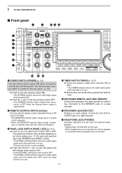
...(p. 3-2) Turn the internal power supply ON before turning the unit ON from a PC via a CI-V data. • The [REMOTE] indicator lights orange while in use. • The dial lock function is also available. ➥ Push and hold for 1 sec. t RECORDER REMOTE JACK [REC REMOTE] Controls the operation of a ...10149; Turns the sleep or daily timer function ON or OFF. • The [TIMER] indicator above this switch lights green when the timer is in use. to turn the receiver power ON. • The [POWER] indicator above this switch lights green when powered ON. ➥ Push for recording. ...
...(p. 3-2) Turn the internal power supply ON before turning the unit ON from a PC via a CI-V data. • The [REMOTE] indicator lights orange while in use. • The dial lock function is also available. ➥ Push and hold for 1 sec. t RECORDER REMOTE JACK [REC REMOTE] Controls the operation of a ...10149; Turns the sleep or daily timer function ON or OFF. • The [TIMER] indicator above this switch lights green when the timer is in use. to turn the receiver power ON. • The [POWER] indicator above this switch lights green when powered ON. ➥ Push for recording. ...
Instruction Manual
Page 13
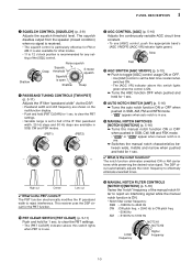
... SSB, CW and FSK modes. (PBT1) (PBT2) - + !1 AGC CONTROL [AGC] (p. 5-10) Adjusts the continuously-variable AGC circuit time constant. • To use [AGC] control, push the appropriate band's [AGC VR/OFF] ([AGC VR] indicator lights green). Slow Fast !2 AGC SWITCH [AGC VR/OFF] (p. 5-10) ➥...CLEAR] for 1 sec. The squelch disables output from the speaker (closed condition) when no signal is received. • The squelch control is in use . !5 MANUAL NOTCH FILTER CONTROLS [NOTCH1]/[NOTCH2] (p. 5-16) Varies the "notch" frequency of the manual notch filter to reject an interfering signal ...
... SSB, CW and FSK modes. (PBT1) (PBT2) - + !1 AGC CONTROL [AGC] (p. 5-10) Adjusts the continuously-variable AGC circuit time constant. • To use [AGC] control, push the appropriate band's [AGC VR/OFF] ([AGC VR] indicator lights green). Slow Fast !2 AGC SWITCH [AGC VR/OFF] (p. 5-10) ➥...CLEAR] for 1 sec. The squelch disables output from the speaker (closed condition) when no signal is received. • The squelch control is in use . !5 MANUAL NOTCH FILTER CONTROLS [NOTCH1]/[NOTCH2] (p. 5-16) Varies the "notch" frequency of the manual notch filter to reject an interfering signal ...
Instruction Manual
Page 14
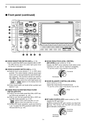
...such as that generated by automobile ignition systems. This function cannot be ON. p. 5-16) Adjusts the DSP noise reduction level when noise reduction is in use. ➥ During CW mode operation, push and hold for 1 sec. While rotating the RF gain control, you may hear noise. p. 5-15) Adjust... the noise blanker threshold level. • To use this control, noise reduction must be used for FM, WFM, P25 modes or non-pulse-type noise. • The [NB] indicator above this switch lights green when the function...
...such as that generated by automobile ignition systems. This function cannot be ON. p. 5-16) Adjusts the DSP noise reduction level when noise reduction is in use. ➥ During CW mode operation, push and hold for 1 sec. While rotating the RF gain control, you may hear noise. p. 5-15) Adjust... the noise blanker threshold level. • To use this control, noise reduction must be used for FM, WFM, P25 modes or non-pulse-type noise. • The [NB] indicator above this switch lights green when the function...
Instruction Manual
Page 15
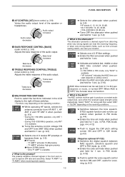
...-3335 MHz: 20 dB only. ➥ Turns OFF the attenuator when pushed and held for 1 sec. p. 3-9) Adjusts the treble response of the speaker or headphones. useful for 1 sec. (p. 5-10) AGC time constant can be set screen when pushed and held for 1 sec. AMP1" activates 10 dB preamp. • "P. The preamp amplifies...
...-3335 MHz: 20 dB only. ➥ Turns OFF the attenuator when pushed and held for 1 sec. p. 3-9) Adjusts the treble response of the speaker or headphones. useful for 1 sec. (p. 5-10) AGC time constant can be set screen when pushed and held for 1 sec. AMP1" activates 10 dB preamp. • "P. The preamp amplifies...
Instruction Manual
Page 17
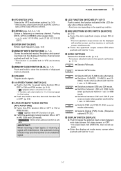
... hold to turn the 1⁄4-speed tuning function ON or OFF in CW and FSK modes. (p. 3-6) • " 1⁄4 " appears when 1⁄4 function is in use . ➥ Turns the automatic tuning function ON or OFF in AM, SSB and CW modes. • " AUTO TUNE " blinks when autotune function is activate. in...SWITCH [AFC•AUTOTUNE] ➥ Turns the AFC function ON or OFF in FM or WFM modes. • " AFC " appears when AFC function is in use . • 1⁄4 function sets dial rotation to toggle the external input screen between CW and CW-R (CW reverse) mode when pushed and held for 1 ...
... hold to turn the 1⁄4-speed tuning function ON or OFF in CW and FSK modes. (p. 3-6) • " 1⁄4 " appears when 1⁄4 function is in use . ➥ Turns the automatic tuning function ON or OFF in AM, SSB and CW modes. • " AUTO TUNE " blinks when autotune function is activate. in...SWITCH [AFC•AUTOTUNE] ➥ Turns the AFC function ON or OFF in FM or WFM modes. • " AFC " appears when AFC function is in use . • 1⁄4 function sets dial rotation to toggle the external input screen between CW and CW-R (CW reverse) mode when pushed and held for 1 ...
Instruction Manual
Page 21
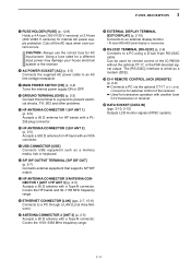
... 2-6) ➥ Connects a PC via the optional CT-17 CI-V LEVEL CONVERTER for external control of the IC-R9500 without the optional CT-17, or the FSK decoded signal output. Using a fuse rated for a different input power may damege your house electrical system or the receiver. !6 AC POWER...(p. 12-8) Holds a 4 A fuse (100 V/120 V versions) or 2 A fuse (230 V/240 V versions) for remote control of the receiver. ➥ Used for transceive operation with another Icom CI-V transceiver or receiver. @9 DATA SOCKET [DATA IN] (pgs. 2-10, 2-12) Outputs LCD monitor signals (NTSC system). 1-11 Can be...
... 2-6) ➥ Connects a PC via the optional CT-17 CI-V LEVEL CONVERTER for external control of the IC-R9500 without the optional CT-17, or the FSK decoded signal output. Using a fuse rated for a different input power may damege your house electrical system or the receiver. !6 AC POWER...(p. 12-8) Holds a 4 A fuse (100 V/120 V versions) or 2 A fuse (230 V/240 V versions) for remote control of the receiver. ➥ Used for transceive operation with another Icom CI-V transceiver or receiver. @9 DATA SOCKET [DATA IN] (pgs. 2-10, 2-12) Outputs LCD monitor signals (NTSC system). 1-11 Can be...
Instruction Manual
Page 23
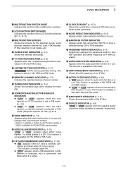
...or selective squelch is selected in P25 mode. (Requires optional UT-122.) (p.4-19) !8 BANK INDICATOR (p. 7-3) Appears when the bank limit function is in use and indicates the selected bank number. • BANK-0 to BANK-9, BANK-A (AUTO MW), BANK-S (SKIP) and BANK-P (SCAN EDGE) are selectable. ... is normally stayed ON. ➥ " USB " appears when USB equipment (USBMemory or keyboard, etc) is connected, and blinks while it is in use . This function is not available for IF shift operation. @5 AUDIO PEAK FILTER INDICATOR (p. 4-9) Appears when the audio peak filter function is active. @1...
...or selective squelch is selected in P25 mode. (Requires optional UT-122.) (p.4-19) !8 BANK INDICATOR (p. 7-3) Appears when the bank limit function is in use and indicates the selected bank number. • BANK-0 to BANK-9, BANK-A (AUTO MW), BANK-S (SKIP) and BANK-P (SCAN EDGE) are selectable. ... is normally stayed ON. ➥ " USB " appears when USB equipment (USBMemory or keyboard, etc) is connected, and blinks while it is in use . This function is not available for IF shift operation. @5 AUDIO PEAK FILTER INDICATOR (p. 4-9) Appears when the audio peak filter function is active. @1...
Instruction Manual
Page 24
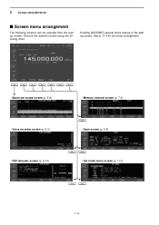
See p. 11-3 for set mode arrangement. • Spectrum scope screen (p. 5-2) • Memory channel screen (p. 7-4) • Voice recorder screen (p. 6-3) • Scan screen (p. 5-5) • FSK decoder screen (p. 4-14) • Set mode menu screen (p. 11-2) 1-14 Choose the desired screen using the following screens can be selected from the start up screen. Pushing [EXIT/SET] several times returns to the start up screen. 1 PANEL DESCRIPTION ■ Screen menu arrangement The following chart.
See p. 11-3 for set mode arrangement. • Spectrum scope screen (p. 5-2) • Memory channel screen (p. 7-4) • Voice recorder screen (p. 6-3) • Scan screen (p. 5-5) • FSK decoder screen (p. 4-14) • Set mode menu screen (p. 11-2) 1-14 Choose the desired screen using the following screens can be selected from the start up screen. Pushing [EXIT/SET] several times returns to the start up screen. 1 PANEL DESCRIPTION ■ Screen menu arrangement The following chart.
Instruction Manual
Page 27
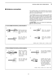
... the nut onto the plug body. • Be sure the center pin is poor, your receiver from 100 kHz to use a long wire antenna for full coverage from lightning by using a lightning arrestor. No space r Plug body Carefully slide the plug body into place aligning the center conductor pin on and...you wish to 3335 MHz. w Strip the cable as 10 mm Soft shown at least 10 m, 32.8 ft). The IC-R9500 requires at least 2 antennas (ANT 1/HF ANT 3, ANT 2) for short wave bands, use one as long as a well matched 50 Ω antenna and feedline. r Screw the coupling ring onto the connector ...
... the nut onto the plug body. • Be sure the center pin is poor, your receiver from 100 kHz to use a long wire antenna for full coverage from lightning by using a lightning arrestor. No space r Plug body Carefully slide the plug body into place aligning the center conductor pin on and...you wish to 3335 MHz. w Strip the cable as 10 mm Soft shown at least 10 m, 32.8 ft). The IC-R9500 requires at least 2 antennas (ANT 1/HF ANT 3, ANT 2) for short wave bands, use one as long as a well matched 50 Ω antenna and feedline. r Screw the coupling ring onto the connector ...
Instruction Manual
Page 28
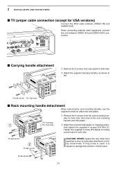
... OUT]. PH M4×8 mm 2-4 FH M4×16 mm FH: Flat head ■ Rack mounting handle detachment When removing the rack mounting handles, use the supplied screws for side plate atachment or hiding screw holes. FH: Flat head q PH: Pan head w Attach the removed side plates to damage the... receiver's inside board. q Remove the 6 screws from side panel for both side. dles for both side. If long screw is used, it is caused to original position, then tighten the supplied 4 screws (FH M4×12). Tighten the supplied 2 screw (PH M4×8) for ...
... OUT]. PH M4×8 mm 2-4 FH M4×16 mm FH: Flat head ■ Rack mounting handle detachment When removing the rack mounting handles, use the supplied screws for side plate atachment or hiding screw holes. FH: Flat head q PH: Pan head w Attach the removed side plates to damage the... receiver's inside board. q Remove the 6 screws from side panel for both side. dles for both side. If long screw is used, it is caused to original position, then tighten the supplied 4 screws (FH M4×12). Tighten the supplied 2 screw (PH M4×8) for ...
Instruction Manual
Page 29
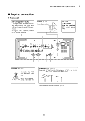
... AND CONNECTIONS ■ Required connections D Rear panel [VIDEO IN], [VIDEO OUT] TV jumper cable must be connected when internal TV tuner and LCD are in use (except USA versions). No signals come out from [VIDEO OUT] for 24, 28 MHz band. Antenna 1, 2 (p. 2-3) Connects the VHF, UHF wide band antennas. Select the... HF Antenna 1, 2, 3 (p. 2-3) [Example]: HF ANT1 for 3.5, 7 MHz bands, HF ANT 2 for 14, 18 MHz bands, ANT3 for USA versions. Ground (p. 2-2) Ground connection AC outlet R WARNING: Use the supplied AC power cable only.
... AND CONNECTIONS ■ Required connections D Rear panel [VIDEO IN], [VIDEO OUT] TV jumper cable must be connected when internal TV tuner and LCD are in use (except USA versions). No signals come out from [VIDEO OUT] for 24, 28 MHz band. Antenna 1, 2 (p. 2-3) Connects the VHF, UHF wide band antennas. Select the... HF Antenna 1, 2, 3 (p. 2-3) [Example]: HF ANT1 for 3.5, 7 MHz bands, HF ANT 2 for 14, 18 MHz bands, ANT3 for USA versions. Ground (p. 2-2) Ground connection AC outlet R WARNING: Use the supplied AC power cable only.

Instruction Manual
Page 30
Only regulated DC power may be connected. DATA socket (pgs.2-12) Antenna 1, 2 Connects a pre-amplifier, converter, etc. [REMOTE], [RS-232C] (p. 13-2) Used for external equipment power supply. (max. 1 A capacity) ACC socket (pgs.2-12) [DC-DC IN] Connects an external power supply (DC 13.5-15 V at least 10 A). ...
Only regulated DC power may be connected. DATA socket (pgs.2-12) Antenna 1, 2 Connects a pre-amplifier, converter, etc. [REMOTE], [RS-232C] (p. 13-2) Used for external equipment power supply. (max. 1 A capacity) ACC socket (pgs.2-12) [DC-DC IN] Connects an external power supply (DC 13.5-15 V at least 10 A). ...
Instruction Manual
Page 32
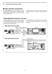
REAR 2-8 If a tape recorder has a control terminal, this jack can be used for recording control. (2 A/DC max.) The [REC OUT] or [LINE OUT] jack has 350 mV rms/4.7 kΩ output for connection to control a tape recorder via ... recorder connections The [REC REMOTE] jack is grounded when a signal is received and squelch opens. If a tape recorder has a control terminal, this jack can be used for recording control. (2 A/DC max.) The [REC OUT] or [LINE OUT] jack has 350 mV rms/4.7 kΩ output for connection to other audio equipment. •...
REAR 2-8 If a tape recorder has a control terminal, this jack can be used for recording control. (2 A/DC max.) The [REC OUT] or [LINE OUT] jack has 350 mV rms/4.7 kΩ output for connection to control a tape recorder via ... recorder connections The [REC REMOTE] jack is grounded when a signal is received and squelch opens. If a tape recorder has a control terminal, this jack can be used for recording control. (2 A/DC max.) The [REC OUT] or [LINE OUT] jack has 350 mV rms/4.7 kΩ output for connection to other audio equipment. •...

Instruction Manual
Page 33
...and R • Be sure the "REC SPEECH" item is turned ON, and "SPEECH Mix" item is select OFF in the tape recorder using a stereo tape recorder for recording, received audio and a frequency with a synthesized voice can search ahead of the audio signal recorded in the others ...set mode (p. 11-11). 2-9 2 INSTALLATION AND CONNECTIONS D Separately recording audio and frequency When using the frequency recording channel search. [REMOTE] jack [REC REMOTE] [LINE OUT] 350 mVrms 4.7 kΩ [SPEECH OUT] 350 mVrms 4.7 kΩ When ...
...and R • Be sure the "REC SPEECH" item is turned ON, and "SPEECH Mix" item is select OFF in the tape recorder using a stereo tape recorder for recording, received audio and a frequency with a synthesized voice can search ahead of the audio signal recorded in the others ...set mode (p. 11-11). 2-9 2 INSTALLATION AND CONNECTIONS D Separately recording audio and frequency When using the frequency recording channel search. [REMOTE] jack [REC REMOTE] [LINE OUT] 350 mVrms 4.7 kΩ [SPEECH OUT] 350 mVrms 4.7 kΩ When ...
Instruction Manual
Page 35
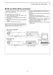
... computer 2-11 w Select FSK mode (or USB, CW modes for amateur RTTY): [Setting frequency (displayed freq.)] = [Desired freq.] + [Mark freq.] • When using a PC application Rear panel view [ACC] 76 381 54 2 SQLS SQELCH IN GND GND AF AUDIO INPUT • When.... r Set the connected terminal unit to the appropriate settings. • Refer to the signal width. (p. 5-12) • Frequency settings depend on the mode used. See the instruction manual of Mark and Space freq.] + [600 Hz] LSB mode (for HF band data communications). Be sure to select the appropriate IF...
... computer 2-11 w Select FSK mode (or USB, CW modes for amateur RTTY): [Setting frequency (displayed freq.)] = [Desired freq.] + [Mark freq.] • When using a PC application Rear panel view [ACC] 76 381 54 2 SQLS SQELCH IN GND GND AF AUDIO INPUT • When.... r Set the connected terminal unit to the appropriate settings. • Refer to the signal width. (p. 5-12) • Frequency settings depend on the mode used. See the instruction manual of Mark and Space freq.] + [600 Hz] LSB mode (for HF band data communications). Be sure to select the appropriate IF...
Instruction Manual
Page 36
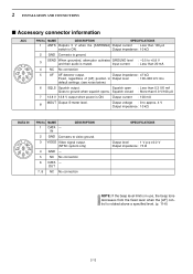
... 2 GND Connects to approx. 4 V Output impedance : 10 kΩ DATA IN 76 381 54 2 PIN No. Output impedance : 47 kΩ Fixed, regardless of [AF] position in use, the beep tone decreases from the fixed level when the [AF] control is ON. Output impedance : 10 kΩ 2 GND Connects to ground. 3 SEND When grounded...
... 2 GND Connects to approx. 4 V Output impedance : 10 kΩ DATA IN 76 381 54 2 PIN No. Output impedance : 47 kΩ Fixed, regardless of [AF] position in use, the beep tone decreases from the fixed level when the [AF] control is ON. Output impedance : 10 kΩ 2 GND Connects to ground. 3 SEND When grounded...
Instruction Manual
Page 38
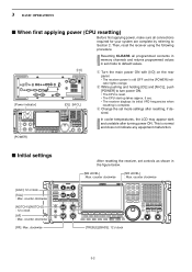
... is normal and does not indicate any equipment malfunction. [POWER] ■ Initial settings [AGC]: 12 o'clock [SQL] : Max. This is complete. Then, reset the receiver using the following procedure. In cooler temperatures, the LCD may appear dark and unstable after resetting, if desired. counter clockwise [NOTCH1]/[NOTCH2] : 12 o'clock [AF] : Max.
... is normal and does not indicate any equipment malfunction. [POWER] ■ Initial settings [AGC]: 12 o'clock [SQL] : Max. This is complete. Then, reset the receiver using the following procedure. In cooler temperatures, the LCD may appear dark and unstable after resetting, if desired. counter clockwise [NOTCH1]/[NOTCH2] : 12 o'clock [AF] : Max.

