

English Manual
Page 1
... all precautions and instructions in the space above for future reference. The trained technicians on our customer hot line will guarantee you . IMBE53901 Serial No. As a manufacturer, we are missing parts, we will provide immediate assistance, free of charge to providing complete customer satisfaction. USER'S MANUAL Visit our website at www.imagefitness.com new products, prizes, fitness tips, and...
... all precautions and instructions in the space above for future reference. The trained technicians on our customer hot line will guarantee you . IMBE53901 Serial No. As a manufacturer, we are missing parts, we will provide immediate assistance, free of charge to providing complete customer satisfaction. USER'S MANUAL Visit our website at www.imagefitness.com new products, prizes, fitness tips, and...

English Manual
Page 2
Remove the Part List/Exploded Drawing before beginning assembly. IMAGE is attached in the center of ICON Health & Fitness, Inc. 2 Table of Contents Important Precautions 3 Before You Begin 4 Part Identification Chart 5 Assembly 6 Adjusting the Weight Bench 13 Ordering Replacement Parts Back Cover Limited Warranty Back Cover Note: A Part List/Exploded Drawing is a registered trademark of this manual.
Remove the Part List/Exploded Drawing before beginning assembly. IMAGE is attached in the center of ICON Health & Fitness, Inc. 2 Table of Contents Important Precautions 3 Before You Begin 4 Part Identification Chart 5 Assembly 6 Adjusting the Weight Bench 13 Ordering Replacement Parts Back Cover Limited Warranty Back Cover Note: A Part List/Exploded Drawing is a registered trademark of this manual.

English Manual
Page 3
... not allow children on page 4. ! Replace any exercise program, consult your weights (not included) with pre-existing health problems. Read all instructions before using. Keep children under 12 and pets away from moving parts. 8. Always secure your physician. Read all instructions in this manual before using the weight bench. If a decal is the responsibility of the owner to ensure that all users of all precautions. 3. Keep hands...
... not allow children on page 4. ! Replace any exercise program, consult your weights (not included) with pre-existing health problems. Read all instructions before using. Keep children under 12 and pets away from moving parts. 8. Always secure your physician. Read all instructions in this manual before using the weight bench. If a decal is the responsibility of the owner to ensure that all users of all precautions. 3. Keep hands...

English Manual
Page 4
... the parts that are determined relative to help us assist you for selecting the versatile IMAGE® 4.5 weight bench. Pull-up Bar Weight Guide Right Side Barbell Weight Glider Safety Spotter Backrest Seat Leg Lever Note: The terms "right side" and "left on the drawings in the indicated position, on both sides of the bench. 4 Left Side Upright Dumbbell Storage Rack Weight Storage Tube Backrest Adjustment...
... the parts that are determined relative to help us assist you for selecting the versatile IMAGE® 4.5 weight bench. Pull-up Bar Weight Guide Right Side Barbell Weight Glider Safety Spotter Backrest Seat Leg Lever Note: The terms "right side" and "left on the drawings in the indicated position, on both sides of the bench. 4 Left Side Upright Dumbbell Storage Rack Weight Storage Tube Backrest Adjustment...

English Manual
Page 5
IMBE53901 R1200A M10 x 190mm Bolt (22) M6 x 16mm Screw (3) Large Washer (70) M8 Washer (77) M10 Washer (6) M8 x 20mm Bolt (75) M10 x 25mm Bolt (76) M6 Washer (30) M10 x 25mm Button Head Bolt (69) M10 Nylon Locknut (11) M8 Nylon Locknut (42) M8 x 60mm Bolt (65) M8 x 30mm Bolt (64) M6 x 35mm Bolt (34) M6 x 55mm Screw (4) M8 x 65mm Carriage Bolt (71) M10 x 60mm Button Head Bolt (12) M10 x 65mm Carriage Bolt (66) M8 x 70mm Bolt (41) M10 x 65mm Bolt (68) M10 x 70mm Bolt (21) M10 x 80mm Bolt (31) 5 Part Identification Chart-Model No.
IMBE53901 R1200A M10 x 190mm Bolt (22) M6 x 16mm Screw (3) Large Washer (70) M8 Washer (77) M10 Washer (6) M8 x 20mm Bolt (75) M10 x 25mm Bolt (76) M6 Washer (30) M10 x 25mm Button Head Bolt (69) M10 Nylon Locknut (11) M8 Nylon Locknut (42) M8 x 60mm Bolt (65) M8 x 30mm Bolt (64) M6 x 35mm Bolt (34) M6 x 55mm Screw (4) M8 x 65mm Carriage Bolt (71) M10 x 60mm Button Head Bolt (12) M10 x 65mm Carriage Bolt (66) M8 x 70mm Bolt (41) M10 x 65mm Bolt (68) M10 x 70mm Bolt (21) M10 x 80mm Bolt (31) 5 Part Identification Chart-Model No.

English Manual
Page 6
... parts described in a cleared area and remove the packing materials. Turn the Base so the large hole is completed. • Tighten all parts in the assembly steps may be pre-assembled. • As you have the following information and instructions: Make Things Easier for Yourself! This manual is in the position shown. Assembly Before beginning assembly, carefully read the following tools: A socket set, a set of open...
... parts described in a cleared area and remove the packing materials. Turn the Base so the large hole is completed. • Tighten all parts in the assembly steps may be pre-assembled. • As you have the following information and instructions: Make Things Easier for Yourself! This manual is in the position shown. Assembly Before beginning assembly, carefully read the following tools: A socket set, a set of open...
English Manual
Page 7
... Do not tighten the Nylon Locknuts yet. Repeat this step on the right Base (46) with two M10 Nylon Locknuts (11). Thread an M10 Nylon Locknut (11) onto each Bolt. Slide the Upright (43) and the Brace (44) onto the M10 x 65mm Carriage Bolts (66) and the M8 x 65mm Carriage Bolts (71)... Attach the Upright with the other Weight Storage Tube (55). Thread an M10 Nylon Locknut (11) onto each Bolt. Do not tighten the Nylon Locknuts yet. 21 39 39 21 55 21 47 44 11 7 Attach the Brace with two M10 x 65mm Bolts (68), four M10 Washers (6), and two M10 Nylon Locknuts (11). Press ...
... Do not tighten the Nylon Locknuts yet. Repeat this step on the right Base (46) with two M10 Nylon Locknuts (11). Thread an M10 Nylon Locknut (11) onto each Bolt. Slide the Upright (43) and the Brace (44) onto the M10 x 65mm Carriage Bolts (66) and the M8 x 65mm Carriage Bolts (71)... Attach the Upright with the other Weight Storage Tube (55). Thread an M10 Nylon Locknut (11) onto each Bolt. Do not tighten the Nylon Locknuts yet. 21 39 39 21 55 21 47 44 11 7 Attach the Brace with two M10 x 65mm Bolts (68), four M10 Washers (6), and two M10 Nylon Locknuts (11). Press ...

English Manual
Page 8
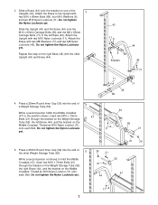
...60) onto the left end of the round tube on page 4 to the left end. The Left Weight Glider must be turned as shown. Attach the Top Crossbar (48) to make sure that the pull-up Bar 11 43 43 51 21 21 7. Have a second person hold the Top Crossbar (48) so that... have correctly identified the left Upright (43) with the Right Weight Glider (not shown). 8 63 73 58 60 75 58 Round tube Repeat this step with two M10 x 70mm Bolts (21), a Small Support Plate (51), and two M10 Nylon Locknuts (11). Press a 25mm Bushing (73) into each end of the Locking Bar (62). 7 Insert the ...
...60) onto the left end of the round tube on page 4 to the left end. The Left Weight Glider must be turned as shown. Attach the Top Crossbar (48) to make sure that the pull-up Bar 11 43 43 51 21 21 7. Have a second person hold the Top Crossbar (48) so that... have correctly identified the left Upright (43) with the Right Weight Glider (not shown). 8 63 73 58 60 75 58 Round tube Repeat this step with two M10 x 70mm Bolts (21), a Small Support Plate (51), and two M10 Nylon Locknuts (11). Press a 25mm Bushing (73) into each end of the Locking Bar (62). 7 Insert the ...

English Manual
Page 9
... beginning this step. Note: The handle must fit into the end of the Barbell in the Base (46). Note: Tilt the Weight Guide away from the Upright (43) as you need to the Base (46) with an M8 x 60mm Bolt (65), two M8 Washers (77), and an M8 Nylon Locknut (42). Attach the Weight Guide (53) to perform this step. 11...
... beginning this step. Note: The handle must fit into the end of the Barbell in the Base (46). Note: Tilt the Weight Guide away from the Upright (43) as you need to the Base (46) with an M8 x 60mm Bolt (65), two M8 Washers (77), and an M8 Nylon Locknut (42). Attach the Weight Guide (53) to perform this step. 11...

English Manual
Page 10
...used in the position shown. Tighten all the Nylon Locknuts used in the same manner. Press a 50mm x 70mm Outer Cap (10) onto each end of the Weight Guides (53) to the other Weight Guide (53) to the bracket on the Upright (43) with an M8 x 12 30mm Bolt (64) and an M8 Washer (77). Attach the Bench... M10 Nylon Locknuts (11). 12. Attach the upper end of one of the Bench Base (7). Attach the other Upright (43) in steps 1 to the Bench Frame (5) with two M10 x 60mm Button Head Bolts (12) and two M10 Nylon Locknuts (11). Note: Do not tighten the Nylon Locknuts yet. 14 20 21...
...used in the position shown. Tighten all the Nylon Locknuts used in the same manner. Press a 50mm x 70mm Outer Cap (10) onto each end of the Weight Guides (53) to the other Weight Guide (53) to the bracket on the Upright (43) with an M8 x 12 30mm Bolt (64) and an M8 Washer (77). Attach the Bench... M10 Nylon Locknuts (11). 12. Attach the upper end of one of the Bench Base (7). Attach the other Upright (43) in steps 1 to the Bench Frame (5) with two M10 x 60mm Button Head Bolts (12) and two M10 Nylon Locknuts (11). Note: Do not tighten the Nylon Locknuts yet. 14 20 21...

English Manual
Page 11
... Backrest Adjustment Bracket (35). Lubricate an M8 x 70mm Bolt (41). Attach the Seat Mounting Bracket (23) to one side. Press two 25mm x 40mm Inner Caps (28) into each Backrest Tube (27). Do not over tighten the Nylon Locknut; Lubricate an M10 x 80mm Bolt (31). Place the Seat Mounting Bracket (23) on the Bench Frame (5) so that the Backrest Tubes are turned as...
... Backrest Adjustment Bracket (35). Lubricate an M8 x 70mm Bolt (41). Attach the Seat Mounting Bracket (23) to one side. Press two 25mm x 40mm Inner Caps (28) into each Backrest Tube (27). Do not over tighten the Nylon Locknut; Lubricate an M10 x 80mm Bolt (31). Place the Seat Mounting Bracket (23) on the Bench Frame (5) so that the Backrest Tubes are turned as...

English Manual
Page 12
... the Seat to the Seat Mounting Bracket with two M6 x 16mm Screws (3). Attach the wide end of the Pad Tubes. 25 16 Insert a Pad Tube (16) through the holes in the Leg Lever (17). 20. Attach the Adjustable Bench Leg (2) to the Adjustable Bench Leg (2) with the Adjustment Knob (37). Note: Do not over tighten the M10 Nylon Locknut; Attach the Leg Lever (17) to the Bench Leg (1) with...
... the Seat to the Seat Mounting Bracket with two M6 x 16mm Screws (3). Attach the wide end of the Pad Tubes. 25 16 Insert a Pad Tube (16) through the holes in the Leg Lever (17). 20. Attach the Adjustable Bench Leg (2) to the Adjustable Bench Leg (2) with the Adjustment Knob (37). Note: Do not over tighten the M10 Nylon Locknut; Attach the Leg Lever (17) to the Bench Leg (1) with...

English Manual
Page 13
... position and turn the Locking Bar until the hooks engage the slots in the Uprights (43). WARNING: Always set both hands. The use the weight bench. See the included exercise guide for that exercise. 43 To do this, stand in the Upright. Inspect and tighten all parts each time you use solvents. The weight bench can be adjusted. USING THE LOCKING BAR AND SAFETY SPOTTERS Before starting on one of...
... position and turn the Locking Bar until the hooks engage the slots in the Uprights (43). WARNING: Always set both hands. The use the weight bench. See the included exercise guide for that exercise. 43 To do this, stand in the Upright. Inspect and tighten all parts each time you use solvents. The weight bench can be adjusted. USING THE LOCKING BAR AND SAFETY SPOTTERS Before starting on one of...
English Manual
Page 14
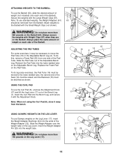
...: To use the Barbell (63), slide the desired amount of weight (not included) onto each side of the Adjustable Bench Leg. ADJUSTING THE PAD TUBES For some exercises, it with the Small Weight Clips (not shown). Secure the weights with Weight Clips (67) when they are on the Leg Lever. ATTACHING WEIGHTS TO THE BARBELL To use standard weights, the Weight Adapters (61) 63 should be removed from...
...: To use the Barbell (63), slide the desired amount of weight (not included) onto each side of the Adjustable Bench Leg. ADJUSTING THE PAD TUBES For some exercises, it with the Small Weight Clips (not shown). Secure the weights with Weight Clips (67) when they are on the Leg Lever. ATTACHING WEIGHTS TO THE BARBELL To use standard weights, the Weight Adapters (61) 63 should be removed from...

English Manual
Page 15
... side of the Backrest Adjustment Bracket (35) with your other hand and pull the Backrest Adjustment Bracket free of the tabs on the bracket on the Bench Frame bracket. Lower the Seat to the desired position and engage the appropriate tab on the Seat Adjustment Bracket to the Bench Frame (5) before using the weight bench. 14 Handle Handle 36 Pin 5 15 35 5 Bracket...
... side of the Backrest Adjustment Bracket (35) with your other hand and pull the Backrest Adjustment Bracket free of the tabs on the bracket on the Bench Frame bracket. Lower the Seat to the desired position and engage the appropriate tab on the Seat Adjustment Bracket to the Bench Frame (5) before using the weight bench. 14 Handle Handle 36 Pin 5 15 35 5 Bracket...

English Manual
Page 16
... limited to give the following information when calling: • The MODEL NUMBER of the product (IMBE53901) • The NAME of the product (IMAGE® 4.5 weight bench) • The SERIAL NUMBER of the product (see the front cover of this manual) • The KEY NUMBER and DESCRIPTION of the desired part(s) (see the PART LIST and the EXPLODED DRAWING at 1-800-999-3756, Monday through Friday, 6 a.m. Limited Warranty ICON Health & Fitness, Inc. (ICON...
... limited to give the following information when calling: • The MODEL NUMBER of the product (IMBE53901) • The NAME of the product (IMAGE® 4.5 weight bench) • The SERIAL NUMBER of the product (see the front cover of this manual) • The KEY NUMBER and DESCRIPTION of the desired part(s) (see the PART LIST and the EXPLODED DRAWING at 1-800-999-3756, Monday through Friday, 6 a.m. Limited Warranty ICON Health & Fitness, Inc. (ICON...

English Manual
Page 17
REMOVE THIS PART LIST/EXPLODED DRAWING FROM THE MANUAL SAVE THIS PART LIST/EXPLODED DRAWING AND THE USER'S MANUAL FOR FUTURE REFERENCE 81
REMOVE THIS PART LIST/EXPLODED DRAWING FROM THE MANUAL SAVE THIS PART LIST/EXPLODED DRAWING AND THE USER'S MANUAL FOR FUTURE REFERENCE 81

English Manual
Page 18
... x 65mm Bolt 69 2 M10 x 25mm Button Head Bolt 70 2 Large Washer 71 4 M8 x 65mm Carriage Bolt 72 2 50mm Bushing 73 2 25mm Bushing 74 8 45mm x 45mm Bushing 75 2 M8 x 20mm Bolt 76 2 M10 x 25mm Bolt 77 10 M8 Washer # 1 User's Manual # 1 Exercise Guide # 1 6mm Allen Wrench Note: "#" indicates a non-illustrated part. See the back cover of the user's manual for information about ordering replacement parts. Description Key No. Part List-Model No...
... x 65mm Bolt 69 2 M10 x 25mm Button Head Bolt 70 2 Large Washer 71 4 M8 x 65mm Carriage Bolt 72 2 50mm Bushing 73 2 25mm Bushing 74 8 45mm x 45mm Bushing 75 2 M8 x 20mm Bolt 76 2 M10 x 25mm Bolt 77 10 M8 Washer # 1 User's Manual # 1 Exercise Guide # 1 6mm Allen Wrench Note: "#" indicates a non-illustrated part. See the back cover of the user's manual for information about ordering replacement parts. Description Key No. Part List-Model No...

English Manual
Page 19
... 66 51 67 21 52 43 11 44 6 6 68 55 21 42 77 39 11 20 46 50 41 71 77 65 R1200A Exploded Drawing-Model No.
... 66 51 67 21 52 43 11 44 6 6 68 55 21 42 77 39 11 20 46 50 41 71 77 65 R1200A Exploded Drawing-Model No.


