
English Product Guide
Page 4
...Gigahertz (one billion hertz) Kilobyte (1024 bytes) Megabyte (1,048,576 bytes) Megabit (1,048,576 bits) Megahertz (one million hertz) Box Contents • Intel® Desktop Board • NVIDIA* GeForce* 6200 LE Graphics Card • I/O shield • One ATA-66/100 cable • Four Serial ...ATA cables • Two Serial ATA power cables • One diskette drive cable • Intel® Express Installer CD-ROM • Floppy disk with RAID driver • Back panel audio covers • Quick Reference Guide • Configuration and battery caution statement label iv...
...Gigahertz (one billion hertz) Kilobyte (1024 bytes) Megabyte (1,048,576 bytes) Megabit (1,048,576 bits) Megahertz (one million hertz) Box Contents • Intel® Desktop Board • NVIDIA* GeForce* 6200 LE Graphics Card • I/O shield • One ATA-66/100 cable • Four Serial ...ATA cables • Two Serial ATA power cables • One diskette drive cable • Intel® Express Installer CD-ROM • Floppy disk with RAID driver • Back panel audio covers • Quick Reference Guide • Configuration and battery caution statement label iv...

English Product Guide
Page 6
... Connecting the Serial ATA Cable 39 Configuring the System for Intel® Matrix Storage Technology for Serial ATA 40 Configuring the BIOS for Intel Matrix Storage Technology 40 Creating Your RAID Set 40 Loading the Intel® Application Accelerator Drivers 40 Setting Up a "RAID Ready" System 40 Connecting... Analog Audio 51 Multi-Channel Digital Audio 51 Replacing the Battery...52 3 BIOS Updating the BIOS ...57 Updating the BIOS with the Intel® Express BIOS Update Utility 57 Updating the BIOS with the Iflash Memory Update Utility 57 4 Desktop Board Resources Memory Map ...61...
... Connecting the Serial ATA Cable 39 Configuring the System for Intel® Matrix Storage Technology for Serial ATA 40 Configuring the BIOS for Intel Matrix Storage Technology 40 Creating Your RAID Set 40 Loading the Intel® Application Accelerator Drivers 40 Setting Up a "RAID Ready" System 40 Connecting... Analog Audio 51 Multi-Channel Digital Audio 51 Replacing the Battery...52 3 BIOS Updating the BIOS ...57 Updating the BIOS with the Intel® Express BIOS Update Utility 57 Updating the BIOS with the Iflash Memory Update Utility 57 4 Desktop Board Resources Memory Map ...61...

English Product Guide
Page 10
... monitor with: • Four fan sensing inputs used to monitor fan activity • Remote diode temperature sensing • Intel® Precision Cooling Technology fan speed control that automatically adjusts processor fan speeds based on processor temperature and chassis fan speeds ... to detect out of range values Related Links For more information about Intel Desktop Board D925XHY, including the Technical Product Specification (TPS), BIOS updates, and device drivers, go to: http://support.intel.com/support/motherboards/desktop/ Supported Operating Systems The desktop board supports the...
... monitor with: • Four fan sensing inputs used to monitor fan activity • Remote diode temperature sensing • Intel® Precision Cooling Technology fan speed control that automatically adjusts processor fan speeds based on processor temperature and chassis fan speeds ... to detect out of range values Related Links For more information about Intel Desktop Board D925XHY, including the Technical Product Specification (TPS), BIOS updates, and device drivers, go to: http://support.intel.com/support/motherboards/desktop/ Supported Operating Systems The desktop board supports the...

English Product Guide
Page 12
...Rear chassis fan header (fan speed control) Alternate power connector (1x4) 12 V power connector (2x2) Processor socket (LGA775) Processor fan header (4-pin, fan speed control) Main power connector (2x12) Diskette drive connector IDE ...Intel Desktop Board D925XHY http://www.intel.com/design/motherbd http://support.intel.com/support/motherboards/desktop • Supported processors http://support.intel.com/support/motherboards/desktop • Audio software and utilities http://www.intel.com/design/motherbd • LAN software and drivers http://www.intel.com/design/motherbd 12 Intel...
...Rear chassis fan header (fan speed control) Alternate power connector (1x4) 12 V power connector (2x2) Processor socket (LGA775) Processor fan header (4-pin, fan speed control) Main power connector (2x12) Diskette drive connector IDE ...Intel Desktop Board D925XHY http://www.intel.com/design/motherbd http://support.intel.com/support/motherboards/desktop • Supported processors http://support.intel.com/support/motherboards/desktop • Audio software and utilities http://www.intel.com/design/motherbd • LAN software and drivers http://www.intel.com/design/motherbd 12 Intel...
English Product Guide
Page 15
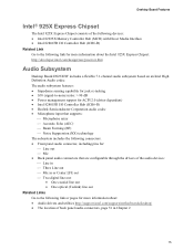
...Impedance sensing capability for jack re-tasking • S/N (signal-to-noise) ratio: > 90 dB • Power management support for ACPI 2.0 (driver dependent) • Intel 82801FR I/O Controller Hub (ICH6-R) • Realtek Semiconductor Corporation audio codec • Microphone input that supports: ⎯ Microphone array ⎯ Acoustic Echo... out Related Links Go to the following link or pages for more information about: • Audio drivers and utilities http://support.intel.com/support/motherboards/desktop/ • The location of back panel audio connectors, page 51 in Chapter 2 15
...Impedance sensing capability for jack re-tasking • S/N (signal-to-noise) ratio: > 90 dB • Power management support for ACPI 2.0 (driver dependent) • Intel 82801FR I/O Controller Hub (ICH6-R) • Realtek Semiconductor Corporation audio codec • Microphone input that supports: ⎯ Microphone array ⎯ Acoustic Echo... out Related Links Go to the following link or pages for more information about: • Audio drivers and utilities http://support.intel.com/support/motherboards/desktop/ • The location of back panel audio connectors, page 51 in Chapter 2 15

English Product Guide
Page 16
...; Programmable transit threshold • Configurable EEPROM that contains the MAC address LAN Subsystem Software For LAN software and drivers, refer to the D925XHY link on Intel's World Wide Web site at: http://support.intel.com/support/motherboards/desktop RJ-45 LAN Connector LEDs Table 4 describes the LED states when the board is powered...
...; Programmable transit threshold • Configurable EEPROM that contains the MAC address LAN Subsystem Software For LAN software and drivers, refer to the D925XHY link on Intel's World Wide Web site at: http://support.intel.com/support/motherboards/desktop RJ-45 LAN Connector LEDs Table 4 describes the LED states when the board is powered...

English Product Guide
Page 17
... a full-speed USB device. four ports routed to the back panel and four routed to the cable. USB 2.0 support requires both an operating system and drivers that do not support USB 2.0. BIOS The BIOS provides the Power-On Self-Test (POST), the BIOS Setup program, the PCI and IDE auto-configuration...
... a full-speed USB device. four ports routed to the back panel and four routed to the cable. USB 2.0 support requires both an operating system and drivers that do not support USB 2.0. BIOS The BIOS provides the Power-On Self-Test (POST), the BIOS Setup program, the PCI and IDE auto-configuration...

English Product Guide
Page 40
... Windows installation CD. 2. Creating Your RAID Set 1. Finish the Windows installation and install all necessary drivers. 4. Intel Desktop Board D925XHY Product Guide Configuring the System for Intel® Matrix Storage Technology for Serial ATA Configuring the BIOS for Intel Matrix Storage Technology 1. Assemble your motherboard or after the Power-On-Self-Test (POST) memory...
... Windows installation CD. 2. Creating Your RAID Set 1. Finish the Windows installation and install all necessary drivers. 4. Intel Desktop Board D925XHY Product Guide Configuring the System for Intel® Matrix Storage Technology for Serial ATA Configuring the BIOS for Intel Matrix Storage Technology 1. Assemble your motherboard or after the Power-On-Self-Test (POST) memory...

English Product Guide
Page 51
.... Select the proper connector according to eight speakers. Installing and Replacing Desktop Board Components Setting Up Full 7.1-Channel Surround Sound (Optional) After installing the audio driver from the Intel Express Installer CD-ROM, the multi-channel audio feature can be used. 51
.... Select the proper connector according to eight speakers. Installing and Replacing Desktop Board Components Setting Up Full 7.1-Channel Surround Sound (Optional) After installing the audio driver from the Intel Express Installer CD-ROM, the multi-channel audio feature can be used. 51
Data Sheet
Page 2
... order. Ω Look for systems with the Intel® Pentium® 4 Processor with a processor, chipset, BIOS, operating system, device drivers and applications enabled for more information. Φ Intel® Extended Memory 64 Technology (Intel® EM64T) requires a computer system with HT Technology logo and also including an Intel® 925, 915, or 910 Express Chipset (see the...
... order. Ω Look for systems with the Intel® Pentium® 4 Processor with a processor, chipset, BIOS, operating system, device drivers and applications enabled for more information. Φ Intel® Extended Memory 64 Technology (Intel® EM64T) requires a computer system with HT Technology logo and also including an Intel® 925, 915, or 910 Express Chipset (see the...
Data Sheet
Page 7
... and Decoding 178 10.3.2 DRAM Clock Generation 181 10.3.3 Suspend to RAM and Resume 181 10.3.4 DDR2 On-Die Termination 181 10.3.5 DDR2 Off-Chip Driver Impedance Calibration 181 10.4 PCI Express* ...182 10.4.1 Transaction Layer 182 10.4.2 Data Link Layer 182 10.4.3 Physical Layer 182 10.5 Power Management 183 10....2 Power Characteristics 186 11.3 Signal Groups...187 11.4 General DC Characteristics 189 12 Ballout and Package Information 193 12.1 Ballout...193 12.2 Package Information 219 Intel® 82925X/82925XE MCH Datasheet 7
... and Decoding 178 10.3.2 DRAM Clock Generation 181 10.3.3 Suspend to RAM and Resume 181 10.3.4 DDR2 On-Die Termination 181 10.3.5 DDR2 Off-Chip Driver Impedance Calibration 181 10.4 PCI Express* ...182 10.4.1 Transaction Layer 182 10.4.2 Data Link Layer 182 10.4.3 Physical Layer 182 10.5 Power Management 183 10....2 Power Characteristics 186 11.3 Signal Groups...187 11.4 General DC Characteristics 189 12 Ballout and Package Information 193 12.1 Ballout...193 12.2 Package Information 219 Intel® 82925X/82925XE MCH Datasheet 7
Data Sheet
Page 12
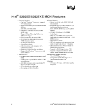
... MCH Features ƒ Processor Interface ƒ System Memory ⎯ One Intel® Pentium® 4 processor (supports ⎯ One or two 64-bit wide DDR2 SDRAM 775-land package) data channels ⎯ Supports Pentium 4 processor FSB interrupt ⎯ Bandwidth up to 8.5 GB/s (DDR2 ... channels) ⎯ GTL+ bus driver with integrated GTL ⎯ SPD (Serial Presence Detect) scheme for termination resistors DIMM detection support ⎯ Supports a Cache Line Size of 64 bytes ⎯ Suspend-to-RAM support using CKE ⎯ Supports Intel Pentium® 4 processors with ⎯...
... MCH Features ƒ Processor Interface ƒ System Memory ⎯ One Intel® Pentium® 4 processor (supports ⎯ One or two 64-bit wide DDR2 SDRAM 775-land package) data channels ⎯ Supports Pentium 4 processor FSB interrupt ⎯ Bandwidth up to 8.5 GB/s (DDR2 ... channels) ⎯ GTL+ bus driver with integrated GTL ⎯ SPD (Serial Presence Detect) scheme for termination resistors DIMM detection support ⎯ Supports a Cache Line Size of 64 bytes ⎯ Suspend-to-RAM support using CKE ⎯ Supports Intel Pentium® 4 processors with ⎯...

Data Sheet
Page 13
...: Unless otherwise specified, the information in the Intel® Extended Memory 64 Technology Software Developer Guide at http://developer.intel.com/technology/64bitextensions/. Select versions of the Pentium 4 processor support Intel EM64T) as an enhancement to take advantage of...which processors support EM64T or consult with a processor, chipset, BIOS, operating system, device drivers and applications enabled for Intel EM64T. For great workstation application flexibility, the Intel® 925X/925XE Express chipset is the sixth generation I/O Controller Hub and provides a multitude...
...: Unless otherwise specified, the information in the Intel® Extended Memory 64 Technology Software Developer Guide at http://developer.intel.com/technology/64bitextensions/. Select versions of the Pentium 4 processor support Intel EM64T) as an enhancement to take advantage of...which processors support EM64T or consult with a processor, chipset, BIOS, operating system, device drivers and applications enabled for Intel EM64T. For great workstation application flexibility, the Intel® 925X/925XE Express chipset is the sixth generation I/O Controller Hub and provides a multitude...
Data Sheet
Page 28
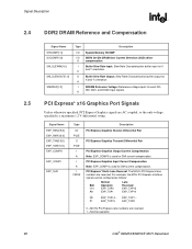
...Reversed C10 EXP_TXP0 EXP_TXP15 A9 EXP_TXP1 EXP_TXP14 ... ... ... P1 EXP_TXP15 EXP_TXP0 0 = MCH's PCI Express lane numbers are reversed 1 = Normal operation 28 Intel® 82925X/82925XE MCH Datasheet Signal Name EXP_RXN[15:0] EXP_RXP[15:0] EXP_TXN[15:0] EXP_TXP[15:0] EXP_COMPO EXP_COMPI EXP_SLR Type I/O PCIE O PCIE I A...[1:0] SM_SLEWOUT[1:0] SMVREF[1:0] Type Description I/O System Memory RCOMP I/O DDR2 On-Die DRAM Over Current Detection (OCD) driver A compensation I Buffer Slew Rate Input: Slew Rate Characterization buffer input for DMI current compensation.
...Reversed C10 EXP_TXP0 EXP_TXP15 A9 EXP_TXP1 EXP_TXP14 ... ... ... P1 EXP_TXP15 EXP_TXP0 0 = MCH's PCI Express lane numbers are reversed 1 = Normal operation 28 Intel® 82925X/82925XE MCH Datasheet Signal Name EXP_RXN[15:0] EXP_RXP[15:0] EXP_TXN[15:0] EXP_TXP[15:0] EXP_COMPO EXP_COMPI EXP_SLR Type I/O PCIE O PCIE I A...[1:0] SM_SLEWOUT[1:0] SMVREF[1:0] Type Description I/O System Memory RCOMP I/O DDR2 On-Die DRAM Over Current Detection (OCD) driver A compensation I Buffer Slew Rate Input: Slew Rate Characterization buffer input for DMI current compensation.
Data Sheet
Page 30
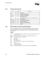
... on the interface from the MCH and does not reflect any external influence (such as external pull-up Weak internal pull-down resistors or external drivers). Strong drive (to the common mode central voltage. DDR2: VCCSM = 1.8 V (VCCSM = 1.9 V for DDR2 533 CAS 3-3-3) 2.5 V CMOS Power. ...input left floating Tri-state Weak internal pull-up /pull-down Strap input sampled during and immediately after the assertion of RSTIN# 30 Intel® 82925X/82925XE MCH Datasheet Ground. Host PLL Analog Power. Signal Description R 2.8 2.9 Power and Ground Name VCC VTT VCC_EXP VCCSM...
... on the interface from the MCH and does not reflect any external influence (such as external pull-up Weak internal pull-down resistors or external drivers). Strong drive (to the common mode central voltage. DDR2: VCCSM = 1.8 V (VCCSM = 1.9 V for DDR2 533 CAS 3-3-3) 2.5 V CMOS Power. ...input left floating Tri-state Weak internal pull-up /pull-down Strap input sampled during and immediately after the assertion of RSTIN# 30 Intel® 82925X/82925XE MCH Datasheet Ground. Host PLL Analog Power. Signal Description R 2.8 2.9 Power and Ground Name VCC VTT VCC_EXP VCCSM...
Data Sheet
Page 76
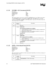
... 1 = The MCH generates an SCI DMI special cycle when the DRAM controller detects a single bit error. 0 = Reporting of BIOS and graphics drivers. For systems not supporting ECC this bit must be enabled. For systems that one and only one message type can generate an SERR, SMI, or... when enabled in the ERRSTS register, it detects a multiple-bit error reported by the DRAM controller. 0 = Reporting of data storage. 00000000 h 76 Intel® 82925X/82925XE MCH Datasheet Host Bridge/DRAM Controller Registers (D0:F0) R 4.1.34 4.1.35 SCICMD-SCI Command (D0:F0) PCI Device: Address Offset...
... 1 = The MCH generates an SCI DMI special cycle when the DRAM controller detects a single bit error. 0 = Reporting of BIOS and graphics drivers. For systems not supporting ECC this bit must be enabled. For systems that one and only one message type can generate an SERR, SMI, or... when enabled in the ERRSTS register, it detects a multiple-bit error reported by the DRAM controller. 0 = Reporting of data storage. 00000000 h 76 Intel® 82925X/82925XE MCH Datasheet Host Bridge/DRAM Controller Registers (D0:F0) R 4.1.34 4.1.35 SCICMD-SCI Command (D0:F0) PCI Device: Address Offset...
Data Sheet
Page 125
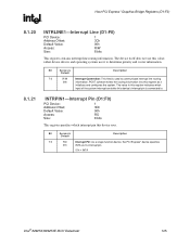
rather device drivers and operating systems use this value; The value in this register indicates which input of the system interrupt controller this device's interrupt pin is used ... Device: Address Offset: Default Value: Access: Size: 1 3Dh 00h RO 8 bits This register specifies which interrupt pin this register as its interrupt pin. 01h = INTA Intel® 82925X/82925XE MCH Datasheet 125 POST software writes the routing information into this device uses. Bit Access & Default Description 7:0 RO Interrupt Pin: As a single...
rather device drivers and operating systems use this value; The value in this register indicates which input of the system interrupt controller this device's interrupt pin is used ... Device: Address Offset: Default Value: Access: Size: 1 3Dh 00h RO 8 bits This register specifies which interrupt pin this register as its interrupt pin. 01h = INTA Intel® 82925X/82925XE MCH Datasheet 125 POST software writes the routing information into this device uses. Bit Access & Default Description 7:0 RO Interrupt Pin: As a single...
Data Sheet
Page 128
...supported. Refer to 0. it . Auxiliary Power Source (APS): Hardwired to the PCI Power Management 1.1 specification for PCI Power Management registers. 128 Intel® 82925X/82925XE MCH Datasheet Pointer to Next Capability: This field contains a pointer to the next item in which this device is NOT required... before generic class device driver is the PCI Express* capability at 90h. D2: Hardwired to 0 to indicate there are 4 bytes of this device may indicate PME ...
...supported. Refer to 0. it . Auxiliary Power Source (APS): Hardwired to the PCI Power Management 1.1 specification for PCI Power Management registers. 128 Intel® 82925X/82925XE MCH Datasheet Pointer to Next Capability: This field contains a pointer to the next item in which this device is NOT required... before generic class device driver is the PCI Express* capability at 90h. D2: Hardwired to 0 to indicate there are 4 bytes of this device may indicate PME ...
Data Sheet
Page 132
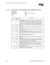
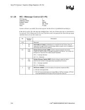
If all of this device to generate MSIs. 0b 0 = MSI will not be generated. 1 = MSI will not be set. 132 Intel® 82925X/82925XE MCH Datasheet This number will be equal to or less than the number actually requested. 000 = 1 message allocated 001-111 = Reserved .... 000 = 1 message requested 001-111 = Reserved 0 R/W MSI Enable (MSIEN) Controls the ability of them must not generate the same message again until the driver services the earlier one of messages allocated to this device. Host-PCI Express* Graphics Bridge Registers (D1:F0) R 8.1.28 MC-Message Control (D1:F0) PCI...
If all of this device to generate MSIs. 0b 0 = MSI will not be generated. 1 = MSI will not be set. 132 Intel® 82925X/82925XE MCH Datasheet This number will be equal to or less than the number actually requested. 000 = 1 message allocated 001-111 = Reserved .... 000 = 1 message requested 001-111 = Reserved 0 R/W MSI Enable (MSIEN) Controls the ability of them must not generate the same message again until the driver services the earlier one of messages allocated to this device. Host-PCI Express* Graphics Bridge Registers (D1:F0) R 8.1.28 MC-Message Control (D1:F0) PCI...
Data Sheet
Page 181
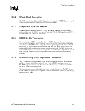
...lines. There are a total of 6 clock pairs driven directly by issuing OCD commands to guide the DRAM through measurement and calibration cycles. Intel® 82925X/82925XE MCH Datasheet 181 In STR, the CKE signals remain LOW so the SDRAM devices will flush pending cycles and then enter...every supported DIMM. It uses a series of the DRAM devices. The MCH adjusts the DRAM driver impedance by the MCH to enable or disable their termination resistance. DDR2 Off-Chip Driver Impedance Calibration The OCD impedance adjustment mode allows the MCH to be located inside the DRAM devices...
...lines. There are a total of 6 clock pairs driven directly by issuing OCD commands to guide the DRAM through measurement and calibration cycles. Intel® 82925X/82925XE MCH Datasheet 181 In STR, the CKE signals remain LOW so the SDRAM devices will flush pending cycles and then enter...every supported DIMM. It uses a series of the DRAM devices. The MCH adjusts the DRAM driver impedance by the MCH to enable or disable their termination resistance. DDR2 Off-Chip Driver Impedance Calibration The OCD impedance adjustment mode allows the MCH to be located inside the DRAM devices...