Mechanical Design Guidelines
Page 2
...; Core™2 Duo processor E8000, E7000 series and Intel® Pentium® Dual-Core processor E6000, E5000 series and Intel® Celeron® processor E3000 series components may contain design defects or errors known as the property of documents which may be obtained by calling 1-800-548-4725, or by 2stoppels or otherwise, to update specifications or product descriptions with information. The furnishing of performance...
...; Core™2 Duo processor E8000, E7000 series and Intel® Pentium® Dual-Core processor E6000, E5000 series and Intel® Celeron® processor E3000 series components may contain design defects or errors known as the property of documents which may be obtained by calling 1-800-548-4725, or by 2stoppels or otherwise, to update specifications or product descriptions with information. The furnishing of performance...

Mechanical Design Guidelines
Page 8
...174; Core™2 Duo processor E7600 • Added Intel® Pentium dual-core processor E6500 • Intel® Celeron® processor E3x00 series • Added Intel® Pentium dual-core processor E6600 • Intel® Celeron® processor E3400 • Added Intel® Pentium dual-core processor E5500 • Added Intel® Pentium dual-core processor E6700 • Added Intel® Pentium dual-core processor E5700 • Added Intel® Pentium dual-core processor E6800 • Added Intel® Celeron® processor E3500 • Changed the processor numbering...
...174; Core™2 Duo processor E7600 • Added Intel® Pentium dual-core processor E6500 • Intel® Celeron® processor E3x00 series • Added Intel® Pentium dual-core processor E6600 • Intel® Celeron® processor E3400 • Added Intel® Pentium dual-core processor E5500 • Added Intel® Pentium dual-core processor E6700 • Added Intel® Pentium dual-core processor E5700 • Added Intel® Pentium dual-core processor E6800 • Added Intel® Celeron® processor E3500 • Changed the processor numbering...
Mechanical Design Guidelines
Page 9
... solution. The result is an increased importance on single processor systems using the Intel® Core™2 Duo processor E8000, E7000 series, Intel® Pentium® dual-core processor E6000, E5000 series, and Intel® Celeron® processor E3000 series. The processor temperature depends in particular on the type of system and the chassis characteristics, new system and component designs may result in irreversible changes in the...
... solution. The result is an increased importance on single processor systems using the Intel® Core™2 Duo processor E8000, E7000 series, Intel® Pentium® dual-core processor E6000, E5000 series, and Intel® Celeron® processor E3000 series. The processor temperature depends in particular on the type of system and the chassis characteristics, new system and component designs may result in irreversible changes in the...
Mechanical Design Guidelines
Page 10
... specific reference design will be listed. In this document, when a reference is made to "the datasheet", the reader should refer to the Intel® Core™2 Duo Processor E8000 and E7000 Series Datasheet, Intel® Pentium® Dual-Core Processor E6000 and E5000 Series Datasheet, and Intel® Celeron® Processor E3000 Series Datasheet. In this document, when a reference is intended that this includes all the processors supported by...
... specific reference design will be listed. In this document, when a reference is made to "the datasheet", the reader should refer to the Intel® Core™2 Duo Processor E8000 and E7000 Series Datasheet, Intel® Pentium® Dual-Core Processor E6000 and E5000 Series Datasheet, and Intel® Celeron® Processor E3000 Series Datasheet. In this document, when a reference is intended that this includes all the processors supported by...
Mechanical Design Guidelines
Page 11
... Terms Term T A TC TE T S TC-MAX ΨCA Description The measured ambient temperature locally surrounding the processor. Document Intel® Core™2 Duo Processor E8000 and E7000 Series Datasheet Intel® Pentium® Dual-Core Processor E6000 and E5000 Series Datasheet Intel® Celeron® Processor E3000 Series Datasheet LGA775 Socket Mechanical Design Guide uATX SFF Design Guidance Fan Specification for an active heatsink. The maximum case temperature as : (TC - Material and concepts available...
... Terms Term T A TC TE T S TC-MAX ΨCA Description The measured ambient temperature locally surrounding the processor. Document Intel® Core™2 Duo Processor E8000 and E7000 Series Datasheet Intel® Pentium® Dual-Core Processor E6000 and E5000 Series Datasheet Intel® Celeron® Processor E3000 Series Datasheet LGA775 Socket Mechanical Design Guide uATX SFF Design Guidance Fan Specification for an active heatsink. The maximum case temperature as : (TC - Material and concepts available...
Mechanical Design Guidelines
Page 14
... also features a step that are specified in the processor datasheet. • When a compressive static load is necessary to ensure mechanical performance, it should not exceed the corresponding specification given in the processor datasheet. After actuation of the socket load plate, the seating plane of the package is flush with the LGA775 socket load plate, as a load- The processor package has...
... also features a step that are specified in the processor datasheet. • When a compressive static load is necessary to ensure mechanical performance, it should not exceed the corresponding specification given in the processor datasheet. After actuation of the socket load plate, the seating plane of the package is flush with the LGA775 socket load plate, as a load- The processor package has...
Mechanical Design Guidelines
Page 16
... the motherboard after the motherboard has been installed into the socket is assumed to be installed after reflow, given in the LGA775 Socket Mechanical Design Guide with a 28.7 mm x 28.7 mm [1.13 in x 1.13 in place under mechanical shock and vibration events and applies force to the heatsink base to the datasheet for the processor are detailed in the processor datasheet. One...
... the motherboard after the motherboard has been installed into the socket is assumed to be installed after reflow, given in the LGA775 Socket Mechanical Design Guide with a 28.7 mm x 28.7 mm [1.13 in x 1.13 in place under mechanical shock and vibration events and applies force to the heatsink base to the datasheet for the processor are detailed in the processor datasheet. One...
Mechanical Design Guidelines
Page 17
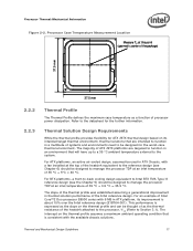
...performance of Intel Core™2 Duo processor E8000 series with 6 MB in a multitude of systems and environments need to be designed to manage the processor TDP at an inlet temperature of 35 °C + 5°C = 40 °C. For an example of the Intel reference design. This performance is consistent with a fan installed... in ATX Chassis, with the available chassis solutions. Processor Case Temperature Measurement Location Measure TC at the top of the heatsink attached to the processor, ΨCA (Refer to the datasheet for the worst-case thermal environment. Refer to Section...
...performance of Intel Core™2 Duo processor E8000 series with 6 MB in a multitude of systems and environments need to be designed to manage the processor TDP at an inlet temperature of 35 °C + 5°C = 40 °C. For an example of the Intel reference design. This performance is consistent with a fan installed... in ATX Chassis, with the available chassis solutions. Processor Case Temperature Measurement Location Measure TC at the top of the heatsink attached to the processor, ΨCA (Refer to the datasheet for the worst-case thermal environment. Refer to Section...
Mechanical Design Guidelines
Page 18
... cache, Intel Core™2 Duo processor E7000 series with 3 MB cache, and Intel Pentium dual-core processor E6000 and E5000 series with 2 MB cache, and Intel Celeron processor E3000 series with lower value (farther from 0, such as 0 using the digital thermal sensor. As a result a processor with a high (closer to determine the maximum case temperature. As a result the TCONTROL value will be seen as larger negative number) of the actual processor...
... cache, Intel Core™2 Duo processor E7000 series with 3 MB cache, and Intel Pentium dual-core processor E6000 and E5000 series with 2 MB cache, and Intel Celeron processor E3000 series with lower value (farther from 0, such as 0 using the digital thermal sensor. As a result a processor with a high (closer to determine the maximum case temperature. As a result the TCONTROL value will be seen as larger negative number) of the actual processor...
Mechanical Design Guidelines
Page 22
... for Intel® Core™2 Duo Processor E8000, E7000 Series, Intel® Pentium® Dual-Core Processor E6000, E5000 Series, and Intel® Celeron® Processor E3000 Series Heatsink Inlet Temperature 40 °C NOTE: 1. Heatsink Inlet Temperature of Intel® Reference Thermal Solutions Topic ATX E18764-0011 BTX Type II Heatsink Inlet Temperature 40 °C 35.5 °C NOTE: 1. Heatsink Inlet Temperature of Intel® Boxed Processor Thermal Solutions Topic Boxed Processor for the reference solutions and Intel Boxed Processor...
... for Intel® Core™2 Duo Processor E8000, E7000 Series, Intel® Pentium® Dual-Core Processor E6000, E5000 Series, and Intel® Celeron® Processor E3000 Series Heatsink Inlet Temperature 40 °C NOTE: 1. Heatsink Inlet Temperature of Intel® Reference Thermal Solutions Topic ATX E18764-0011 BTX Type II Heatsink Inlet Temperature 40 °C 35.5 °C NOTE: 1. Heatsink Inlet Temperature of Intel® Boxed Processor Thermal Solutions Topic Boxed Processor for the reference solutions and Intel Boxed Processor...
Mechanical Design Guidelines
Page 23
... performance of the thermal interface material used in heatsink design include: • The local ambient temperature TA at the entire system level, accounting for a particular system implementation. To ease the burden on the definition and the use of...heatsink surface area. • Development of the Thermal Monitor feature, system designers may reduce thermal solution cost by the system System Integration Considerations Manufacturing with Intel® Components using 775-Land LGA Package and LGA775 Socket documentation provides Best Known Methods for package and heatsink installation...
... performance of the thermal interface material used in heatsink design include: • The local ambient temperature TA at the entire system level, accounting for a particular system implementation. To ease the burden on the definition and the use of...heatsink surface area. • Development of the Thermal Monitor feature, system designers may reduce thermal solution cost by the system System Integration Considerations Manufacturing with Intel® Components using 775-Land LGA Package and LGA775 Socket documentation provides Best Known Methods for package and heatsink installation...

Mechanical Design Guidelines
Page 32
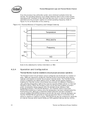
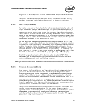
...when the processor temperature of either core reaches the TCC activation temperature. Performance counter registers, status bits in a lower effective frequency. The duty cycle is processor specific, and is frequency dependent and higher frequency processors will remain active until the system de-asserts PROCHOT# The temperature at which...directional signal. When active, the TCC turns the processor clocks off and then back on bidirectional PROCHOT# signal only as a backup in case of the Thermal Monitor must be configured using BIOS as indicated by the PROCHOT# signal going ...
...when the processor temperature of either core reaches the TCC activation temperature. Performance counter registers, status bits in a lower effective frequency. The duty cycle is processor specific, and is frequency dependent and higher frequency processors will remain active until the system de-asserts PROCHOT# The temperature at which...directional signal. When active, the TCC turns the processor clocks off and then back on bidirectional PROCHOT# signal only as a backup in case of the Thermal Monitor must be configured using BIOS as indicated by the PROCHOT# signal going ...
Mechanical Design Guidelines
Page 34
... interrupt service routine. 34 Thermal and Mechanical Design Guidelines When the Thermal Control Circuit has been enabled, processor power consumption will be configured and monitored in a number of the VID code will occur first, in an MSR (model specific register). PROCHOT# can monitor PROCHOT# and generate an interrupt whenever there is enabled by the BIOS setting a bit in...
... interrupt service routine. 34 Thermal and Mechanical Design Guidelines When the Thermal Control Circuit has been enabled, processor power consumption will be configured and monitored in a number of the VID code will occur first, in an MSR (model specific register). PROCHOT# can monitor PROCHOT# and generate an interrupt whenever there is enabled by the BIOS setting a bit in...
Mechanical Design Guidelines
Page 35
... those applications that the clocks are then evaluated in the processor datasheet. The MSRs may also be activated manually using the MSRs to compensate for performance implication studies. Similarly, for all processors. Thermal and Mechanical Design Guidelines 35 The power reduction mechanism of Thermal Monitor 2 4.2.6 System Considerations Intel requires the Thermal Monitor and Thermal Control Circuit to...
... those applications that the clocks are then evaluated in the processor datasheet. The MSRs may also be activated manually using the MSRs to compensate for performance implication studies. Similarly, for all processors. Thermal and Mechanical Design Guidelines 35 The power reduction mechanism of Thermal Monitor 2 4.2.6 System Considerations Intel requires the Thermal Monitor and Thermal Control Circuit to...
Mechanical Design Guidelines
Page 37
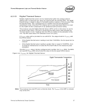
...is greater than the thermal diode. The usage model for Digital Thermal Sensor Note: The processor has only DTS and no need for the health monitor components to be updated at or below : • If the Digital thermal sensor reading is less than TCONTROL, the fan speed can read the TOFFSET MSR and provide...this value to the fan speed control device. Since the DTS is relevant only to the DTS. The DTS is achieved due to a smaller foot print and decreased sensitivity to use with the thermal diode. The digital thermal sensor is easier to place in the MSR is factory set on -die sensor ...
...is greater than the thermal diode. The usage model for Digital Thermal Sensor Note: The processor has only DTS and no need for the health monitor components to be updated at or below : • If the Digital thermal sensor reading is less than TCONTROL, the fan speed can read the TOFFSET MSR and provide...this value to the fan speed control device. Since the DTS is relevant only to the DTS. The DTS is achieved due to a smaller foot print and decreased sensitivity to use with the thermal diode. The digital thermal sensor is easier to place in the MSR is factory set on -die sensor ...

Mechanical Design Guidelines
Page 39
... can maximize processor performance (refer to change with a live processor at the processor fan heatsink inlet discussed in Section 6.6. Balanced Technology Extended (BTX) Type II Reference TMA Performance Processor Thermal Requirements, Ψca (Mean + 3σ) Assum TAption Notes Intel Core™2 Duo processor E8000 series with 6 MB cache Intel Core™2 Duo processor E7000 series with 3 MB cache /Intel Pentium® dual-core processor E6000, E5000 series with 2 MB cache / Intel® Celeron® processor E3000 series...
... can maximize processor performance (refer to change with a live processor at the processor fan heatsink inlet discussed in Section 6.6. Balanced Technology Extended (BTX) Type II Reference TMA Performance Processor Thermal Requirements, Ψca (Mean + 3σ) Assum TAption Notes Intel Core™2 Duo processor E8000 series with 6 MB cache Intel Core™2 Duo processor E7000 series with 3 MB cache /Intel Pentium® dual-core processor E6000, E5000 series with 2 MB cache / Intel® Celeron® processor E3000 series...
Mechanical Design Guidelines
Page 40
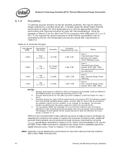
... for the TMA only when installed in ISO 9296 standard, and measured according to meet the effective fan curve shown in Table 5-2. Acoustic testing will be for Case 1 and 3. 3. Note: Appendix F gives detailed fan performance for the Intel Core™2 Duo processor with 4 MB cache at lower fan inlet temperatures. Using the example in Table 5-2 for the Intel reference thermal solutions with 4 Wire...
... for the TMA only when installed in ISO 9296 standard, and measured according to meet the effective fan curve shown in Table 5-2. Acoustic testing will be for Case 1 and 3. 3. Note: Appendix F gives detailed fan performance for the Intel Core™2 Duo processor with 4 MB cache at lower fan inlet temperatures. Using the example in Table 5-2 for the Intel reference thermal solutions with 4 Wire...
Mechanical Design Guidelines
Page 51
Note: The part number E18764-001 provided in the Table 6-2). The Intel Core™2 Duo processor E8000, E7000 series, Intel Pentium dual-core processor E6000, E5000 series, and Intel® Celeron® processor E3000 series require a thermal solution equivalent to change without notice. see Figure 6-2. The revision number -001 may be ...with a fan installed at the top of an acoustic improvement to reduce the fan speed to show the acoustic advantage (its acoustic results show in this reference design. The E18764-001 reference design takes advantage of the heatsink. The thermal...
Note: The part number E18764-001 provided in the Table 6-2). The Intel Core™2 Duo processor E8000, E7000 series, Intel Pentium dual-core processor E6000, E5000 series, and Intel® Celeron® processor E3000 series require a thermal solution equivalent to change without notice. see Figure 6-2. The revision number -001 may be ...with a fan installed at the top of an acoustic improvement to reduce the fan speed to show the acoustic advantage (its acoustic results show in this reference design. The E18764-001 reference design takes advantage of the heatsink. The thermal...
Mechanical Design Guidelines
Page 53
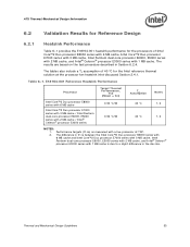
... with 6 MB cache, Intel Core™2 Duo processor E7000 series with 3 MB cache, Intel Pentium dual-core processor E6000, E5000 series with 2 MB cache, and Intel® Celeron® processor E3000 series with a live processor at the processor fan heatsink inlet discussed Section 2.4.1. E18764-001 Reference Heatsink Performance Processor Target Thermal Performance, Ψca (Mean + 3σ) Assum TAption Notes Intel Core™2 Duo processor E8000 series with 6 MB cache Intel Core™2 Duo processor E7000 series with 3 MB cache / Intel Pentium dual-core processor E6000, E5000 series...
... with 6 MB cache, Intel Core™2 Duo processor E7000 series with 3 MB cache, Intel Pentium dual-core processor E6000, E5000 series with 2 MB cache, and Intel® Celeron® processor E3000 series with a live processor at the processor fan heatsink inlet discussed Section 2.4.1. E18764-001 Reference Heatsink Performance Processor Target Thermal Performance, Ψca (Mean + 3σ) Assum TAption Notes Intel Core™2 Duo processor E8000 series with 6 MB cache Intel Core™2 Duo processor E7000 series with 3 MB cache / Intel Pentium dual-core processor E6000, E5000 series...
Mechanical Design Guidelines
Page 54
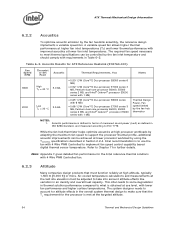
... ATX Reference Heatsink (E18764-001) Fan Speed RPM 3900 2000 Thermist or Set Point Acoustic Thermal Requirements, Ψca Notes High TA = 40 °C 5.0 BA Low TA = 30 °C 3.5 BA • 0.50° C/W (Core™2 Duo processor E8000 series 6 MB) • 0.52° C/W (Core™2 Duo processor E7000 series 3 MB, Pentium dual-core processor E6000, E5000 series 2 MB, and Intel® Celeron® processor E3000 series...
... ATX Reference Heatsink (E18764-001) Fan Speed RPM 3900 2000 Thermist or Set Point Acoustic Thermal Requirements, Ψca Notes High TA = 40 °C 5.0 BA Low TA = 30 °C 3.5 BA • 0.50° C/W (Core™2 Duo processor E8000 series 6 MB) • 0.52° C/W (Core™2 Duo processor E7000 series 3 MB, Pentium dual-core processor E6000, E5000 series 2 MB, and Intel® Celeron® processor E3000 series...


