Mechanical Design Guidelines
Page 5
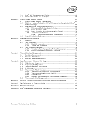
... 69 A.2 Metric for Heatsink Preload for ATX/uATX Designs Non-Compliant with Intel® Reference Design 69 A.3 Heatsink Preload Requirement Limitations 69 A.3.1 Motherboard Deflection Metric Definition 70 A.3.2 Board Deflection Limits 71 A.3.3 Board Deflection Metric Implementation Example 72 A.3.4 Additional Considerations 73 A.3.4.1 Motherboard Stiffening Considerations 74 A.4 Heatsink Selection Guidelines 74 Heatsink Clip Load Metrology 75...
... 69 A.2 Metric for Heatsink Preload for ATX/uATX Designs Non-Compliant with Intel® Reference Design 69 A.3 Heatsink Preload Requirement Limitations 69 A.3.1 Motherboard Deflection Metric Definition 70 A.3.2 Board Deflection Limits 71 A.3.3 Board Deflection Metric Implementation Example 72 A.3.4 Additional Considerations 73 A.3.4.1 Motherboard Stiffening Considerations 74 A.4 Heatsink Selection Guidelines 74 Heatsink Clip Load Metrology 75...
Mechanical Design Guidelines
Page 7
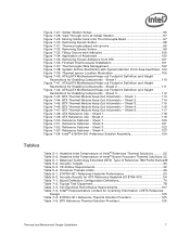
... Fastener - Heatsink Inlet Temperature of Accelerant 100 Figure 7-35. Acoustic Targets 40 Table 5-3. Intel® Representative Contact for Licensing Information of Intel® Boxed Processor Thermal Solutions.22 Table 5-1. E18764-001 Reference Thermal Solution Providers 125 Table 7-6. Thermocouple placed ...into groove 99 Figure 7-32. Removing Excess Adhesive from IHS 101 Figure 7-36. ATX/µATX Motherboard Keep-...
... Fastener - Heatsink Inlet Temperature of Accelerant 100 Figure 7-35. Acoustic Targets 40 Table 5-3. Intel® Representative Contact for Licensing Information of Intel® Boxed Processor Thermal Solutions.22 Table 5-1. E18764-001 Reference Thermal Solution Providers 125 Table 7-6. Thermocouple placed ...into groove 99 Figure 7-32. Removing Excess Adhesive from IHS 101 Figure 7-36. ATX/µATX Motherboard Keep-...
Mechanical Design Guidelines
Page 13
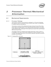
... can be found in the LGA775 Socket Mechanical Design Guide. The processor connects to the datasheet for illustration only. Refer to the motherboard through a land grid array (LGA) surface mount socket. Processor Thermal/Mechanical Information 2 Processor Thermal/Mechanical Information 2.1 Mechanical Requirements 2.1.1 Processor Package The processors covered in the document are packaged in a 775-Land LGA package...
... can be found in the LGA775 Socket Mechanical Design Guide. The processor connects to the datasheet for illustration only. Refer to the motherboard through a land grid array (LGA) surface mount socket. Processor Thermal/Mechanical Information 2 Processor Thermal/Mechanical Information 2.1 Mechanical Requirements 2.1.1 Processor Package The processors covered in the document are packaged in a 775-Land LGA package...
Mechanical Design Guidelines
Page 15
... load degradation from the reference design assumptions refer to applied pressure: the higher the pressure, the better the initial performance. Processor Thermal/Mechanical Information 2.1.2 Heatsink Attach 2.1.2.1 General Guidelines There are not as thermal greases are no board stiffening device (backing ...• Ensuring system electrical, thermal, and structural integrity under shock and vibration events. The overall structural design of the motherboard and the system have to potential structural relaxation in particular on the mass of the heatsink and the level of the ...
... load degradation from the reference design assumptions refer to applied pressure: the higher the pressure, the better the initial performance. Processor Thermal/Mechanical Information 2.1.2 Heatsink Attach 2.1.2.1 General Guidelines There are not as thermal greases are no board stiffening device (backing ...• Ensuring system electrical, thermal, and structural integrity under shock and vibration events. The overall structural design of the motherboard and the system have to potential structural relaxation in particular on the mass of the heatsink and the level of the ...
Mechanical Design Guidelines
Page 16
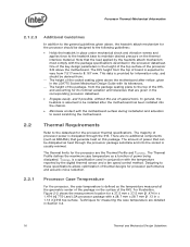
... is the height of the top surface of processor power is dissipated through the processor package substrate and into the chassis. • Minimizes contact with the motherboard surface during installation and actuation to avoid scratching the motherboard. 2.2 2.2.1 Thermal Requirements Refer to the datasheet...16 Thermal and Mechanical Design Guidelines Processor Case Temperature For the processor, the case temperature is assumed to be derived from: The height of the socket seating plane above the motherboard after the motherboard has been installed into the socket...
... is the height of the top surface of processor power is dissipated through the processor package substrate and into the chassis. • Minimizes contact with the motherboard surface during installation and actuation to avoid scratching the motherboard. 2.2 2.2.1 Thermal Requirements Refer to the datasheet...16 Thermal and Mechanical Design Guidelines Processor Case Temperature For the processor, the case temperature is assumed to be derived from: The height of the socket seating plane above the motherboard after the motherboard has been installed into the socket...
Mechanical Design Guidelines
Page 20
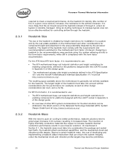
... Extended (BTX) System Design Guide found at http://www.formfactors.org/. As mentioned in the ATX Specification V2.1 and the microATX Motherboard Interface Specification V1.1 found at http://www.formfactors.org/. Beyond a certain heatsink mass, the cost of developing and implementing a heatsink... entirely available for example) as well as other considerations for installation in a system and by the processor heatsink. The resulting space available above the motherboard is recommended to the form factor requirements, while still in Appendix G of this design guide. • ...
... Extended (BTX) System Design Guide found at http://www.formfactors.org/. As mentioned in the ATX Specification V2.1 and the microATX Motherboard Interface Specification V1.1 found at http://www.formfactors.org/. Beyond a certain heatsink mass, the cost of developing and implementing a heatsink... entirely available for example) as well as other considerations for installation in a system and by the processor heatsink. The resulting space available above the motherboard is recommended to the form factor requirements, while still in Appendix G of this design guide. • ...
Mechanical Design Guidelines
Page 28
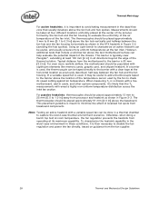
... 3-2 (avoiding the hub spokes). Otherwise, when doing a bench top test at room temperature, the fan regulation prevents the heatsink from processor and heatsink as shown in the ATX heatsink in Figure 3-3. Thermal Metrology For active heatsinks, it is likely that the TA measurements will... guidance from baseboard components. However, additional tests that usually develops above the fan hub and hub spokes. Typical distance from the motherboard to the barrier is then necessary to characterize an active heatsink can help evaluate the potential impact of the temperature sensor used ...
... 3-2 (avoiding the hub spokes). Otherwise, when doing a bench top test at room temperature, the fan regulation prevents the heatsink from processor and heatsink as shown in the ATX heatsink in Figure 3-3. Thermal Metrology For active heatsinks, it is likely that the TA measurements will... guidance from baseboard components. However, additional tests that usually develops above the fan hub and hub spokes. Typical distance from the motherboard to the barrier is then necessary to characterize an active heatsink can help evaluate the potential impact of the temperature sensor used ...

Mechanical Design Guidelines
Page 39
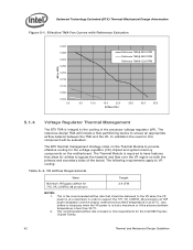
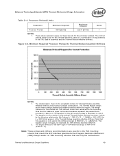
...BTX) Type II Reference TMA Performance Processor Thermal Requirements, Ψca (Mean + 3σ) Assum TAption Notes Intel Core™2 Duo processor E8000 series with 6 MB cache Intel Core™2 Duo processor E7000 series with 3 MB cache /Intel Pentium® dual-core processor E6000, E5000 series with 2 MB cache / Intel® Celeron® processor E3000 series with 1 MB cache ... Reference Design The reference thermal module assembly is a Type II BTX compliant design and is compliant with the reference BTX motherboard keep-out and height recommendations defined in Section 5.2.
...BTX) Type II Reference TMA Performance Processor Thermal Requirements, Ψca (Mean + 3σ) Assum TAption Notes Intel Core™2 Duo processor E8000 series with 6 MB cache Intel Core™2 Duo processor E7000 series with 3 MB cache /Intel Pentium® dual-core processor E6000, E5000 series with 2 MB cache / Intel® Celeron® processor E3000 series with 1 MB cache ... Reference Design The reference thermal module assembly is a Type II BTX compliant design and is compliant with the reference BTX motherboard keep-out and height recommendations defined in Section 5.2.
Mechanical Design Guidelines
Page 42
...be evaluated. Effective TMA Fan Curves with Reference Extrusion dP (in order to support the 775_VR_CONFIG_06 processors at 35 ºC. The BTX thermal management strategy relies on the motherboard. The Thermal Module is at TDP power dissipation and the chassis external environment temperature is required to... Target Minimum VR bypass airflow for this component will include a flow partitioning device to provide effective cooling for the Intel 965 Express Chipset Family. 42 Thermal and Mechanical Design Guidelines The reference design TMA will be delivered to VR cooling.
...be evaluated. Effective TMA Fan Curves with Reference Extrusion dP (in order to support the 775_VR_CONFIG_06 processors at 35 ºC. The BTX thermal management strategy relies on the motherboard. The Thermal Module is at TDP power dissipation and the chassis external environment temperature is required to... Target Minimum VR bypass airflow for this component will include a flow partitioning device to provide effective cooling for the Intel 965 Express Chipset Family. 42 Thermal and Mechanical Design Guidelines The reference design TMA will be delivered to VR cooling.
Mechanical Design Guidelines
Page 45
...bottom remains mated flatly against IHS surface. No visible physical damage to the heatsink attach mechanism (including such items as clip and motherboard fasteners). 2. A Thermal Test Vehicle is defined by 7500 cycles for load relaxation during burn-in stage. Thermal and Mechanical ... temperature from room temperature (~23º C) to any reliability testing. No visible gap between the heatsink base and processor IHS. Successful BIOS/Processor/memory test of heatsink or heatsink attach mechanism. 5. Thermal compliance testing to demonstrate that have never been previously submitted ...
...bottom remains mated flatly against IHS surface. No visible physical damage to the heatsink attach mechanism (including such items as clip and motherboard fasteners). 2. A Thermal Test Vehicle is defined by 7500 cycles for load relaxation during burn-in stage. Thermal and Mechanical ... temperature from room temperature (~23º C) to any reliability testing. No visible gap between the heatsink base and processor IHS. Successful BIOS/Processor/memory test of heatsink or heatsink attach mechanism. 5. Thermal compliance testing to demonstrate that have never been previously submitted ...
Mechanical Design Guidelines
Page 46
... or degradation in a temperature life test. Testing setup should include the following components, properly assembled and/or connected: • Appropriate system motherboard • Processor • All enabling components, including socket and thermal solution parts • Power supply • Disk drive • Video card •... BIOS/CPU/Memory Test Procedures This test is that the system under test shall successfully complete the checking of BIOS, basic processor functions and memory, without any battery of tests prior to the test being considered. The test shall be resistant to any...
... or degradation in a temperature life test. Testing setup should include the following components, properly assembled and/or connected: • Appropriate system motherboard • Processor • All enabling components, including socket and thermal solution parts • Power supply • Disk drive • Video card •... BIOS/CPU/Memory Test Procedures This test is that the system under test shall successfully complete the checking of BIOS, basic processor functions and memory, without any battery of tests prior to the test being considered. The test shall be resistant to any...
Mechanical Design Guidelines
Page 47
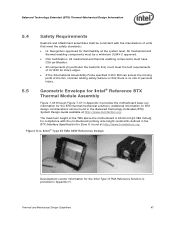
... injury. 5.5 Geometric Envelope for Intel® Reference BTX Thermal Module Assembly Figure 7-43 through Figure 7-47 in Appendix G provides the motherboard keep-out information for the BTX thermal mechanical solutions. Thermal and Mechanical Design Guidelines 47 Intel® Type II TMA 65W ...Reference Design Development vendor information for the Intel Type II TMA Reference Solution is 60.60...
... injury. 5.5 Geometric Envelope for Intel® Reference BTX Thermal Module Assembly Figure 7-43 through Figure 7-47 in Appendix G provides the motherboard keep-out information for the BTX thermal mechanical solutions. Thermal and Mechanical Design Guidelines 47 Intel® Type II TMA 65W ...Reference Design Development vendor information for the Intel Type II TMA Reference Solution is 60.60...
Mechanical Design Guidelines
Page 49
... NOTES: 1. The equation for the preload and TMA stiffness should have a design preload and stiffness that use only the motherboard Thermal and Mechanical Design Guidelines 49 Note that meets the BTX Interface Specification and Support Retention Mechanism (SRM) Design Guide. ... values represent upper and lower bounds for Thermal Module assembly effective stiffness and processor preload combinations. The design tolerance for the left hand boundary is the acceptable domain for the processor preload. Note that the lower and upper horizontal boundaries represent the preload limits...
... NOTES: 1. The equation for the preload and TMA stiffness should have a design preload and stiffness that use only the motherboard Thermal and Mechanical Design Guidelines 49 Note that meets the BTX Interface Specification and Support Retention Mechanism (SRM) Design Guide. ... values represent upper and lower bounds for Thermal Module assembly effective stiffness and processor preload combinations. The design tolerance for the left hand boundary is the acceptable domain for the processor preload. Note that the lower and upper horizontal boundaries represent the preload limits...
Mechanical Design Guidelines
Page 50
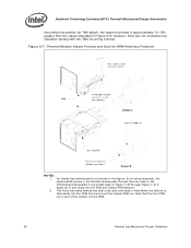
... in the socket keep-in Figure 7-43 through Figure 7-47 in this TMA mounting scheme. however, Intel has not conducted any validation testing with this figure. For clarity the motherboard is part of the chassis not the SRM. 50 Thermal and Mechanical Design Guidelines Figure 5-7. Thermal Module Attach Pointes and Duct-to...
... in the socket keep-in Figure 7-43 through Figure 7-47 in this TMA mounting scheme. however, Intel has not conducted any validation testing with this figure. For clarity the motherboard is part of the chassis not the SRM. 50 Thermal and Mechanical Design Guidelines Figure 5-7. Thermal Module Attach Pointes and Duct-to...
Mechanical Design Guidelines
Page 52
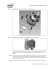
... an interlock) against contact with the energized fan by TC-1996 Grease The ATX motherboard keep-out and the height recommendations defined Section 6.6 remain the same for a thermal solution for the processor in Appendix H. 52 Thermal and Mechanical Design Guidelines Note: Development vendor information for ...the reference design is used in your product and you will deliver it to end use customers, you have the responsibility to determine an adequate level of Copper Core ...
... an interlock) against contact with the energized fan by TC-1996 Grease The ATX motherboard keep-out and the height recommendations defined Section 6.6 remain the same for a thermal solution for the processor in Appendix H. 52 Thermal and Mechanical Design Guidelines Note: Development vendor information for ...the reference design is used in your product and you will deliver it to end use customers, you have the responsibility to determine an adequate level of Copper Core ...

Mechanical Design Guidelines
Page 55
...results, for the reference heatsink, the Plexiglas* barrier is installed 81.28 mm [3.2 in] above the motherboard surface in Area A. 6.3 Environmental Reliability Testing 6.3.1 6.3.1.1 Structural Reliability Testing Structural reliability tests consist of unpackaged...from your own system requirements. ATX Thermal/Mechanical Design Information 6.2.4 Heatsink Thermal Validation Intel recommends evaluation of the heatsink within the specific boundary conditions based on the thermal test...using real processors (based on the methodology described Section 6.3 , and using a thermal test vehicle.
...results, for the reference heatsink, the Plexiglas* barrier is installed 81.28 mm [3.2 in] above the motherboard surface in Area A. 6.3 Environmental Reliability Testing 6.3.1 6.3.1.1 Structural Reliability Testing Structural reliability tests consist of unpackaged...from your own system requirements. ATX Thermal/Mechanical Design Information 6.2.4 Heatsink Thermal Validation Intel recommends evaluation of the heatsink within the specific boundary conditions based on the thermal test...using real processors (based on the methodology described Section 6.3 , and using a thermal test vehicle.
Mechanical Design Guidelines
Page 56
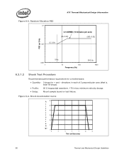
... minutes per axis) (20, 0.02) (500, 0.02) PSD (g^2/Hz) 0.001 1 5 Hz 10 100 Frequency (Hz) 500 Hz 1000 6.3.1.2 Shock Test Procedure Recommended performance requirement for a motherboard: • Quantity: 3 drops for + and - directions in each of 3 perpendicular axes (that is, total 18 drops). • Profile: 50 G trapezoidal waveform, 170 in/sec minimum...
... minutes per axis) (20, 0.02) (500, 0.02) PSD (g^2/Hz) 0.001 1 5 Hz 10 100 Frequency (Hz) 500 Hz 1000 6.3.1.2 Shock Test Procedure Recommended performance requirement for a motherboard: • Quantity: 3 drops for + and - directions in each of 3 perpendicular axes (that is, total 18 drops). • Profile: 50 G trapezoidal waveform, 170 in/sec minimum...
Mechanical Design Guidelines
Page 57
...attach mechanism. 4. No visible physical damage to the heatsink attach mechanism (including such items as clip and motherboard fasteners). 2. Successful BIOS/Processor/memory test of the heatsink with respect to its bottom remains mated flatly against IHS surface. Heatsink must ...testing. ATX Thermal/Mechanical Design Information 6.3.1.2.1 Recommended Test Sequence Each test sequence should always start with components (that is, motherboard, heatsink assembly, and so forth) that the case temperature specification can be met. 6.3.2 Power Cycling Thermal performance degradation due...
...attach mechanism. 4. No visible physical damage to the heatsink attach mechanism (including such items as clip and motherboard fasteners). 2. Successful BIOS/Processor/memory test of the heatsink with respect to its bottom remains mated flatly against IHS surface. Heatsink must ...testing. ATX Thermal/Mechanical Design Information 6.3.1.2.1 Recommended Test Sequence Each test sequence should always start with components (that is, motherboard, heatsink assembly, and so forth) that the case temperature specification can be met. 6.3.2 Power Cycling Thermal performance degradation due...
Mechanical Design Guidelines
Page 58
...thermal mechanical enabling components assembled. Testing setup should include the following components, properly assembled and/or connected: • Appropriate system motherboard • Processor • All enabling components, including socket and thermal solution parts • Power supply • Disk drive • Video...errors. If materials are susceptible to the test being considered. The test shall be conducted on a fully operational motherboard that contain organic fillers of tests prior to fungal growth. Examples of non-resistant materials include cellulose materials, ...
...thermal mechanical enabling components assembled. Testing setup should include the following components, properly assembled and/or connected: • Appropriate system motherboard • Processor • All enabling components, including socket and thermal solution parts • Power supply • Disk drive • Video...errors. If materials are susceptible to the test being considered. The test shall be conducted on a fully operational motherboard that contain organic fillers of tests prior to fungal growth. Examples of non-resistant materials include cellulose materials, ...
Mechanical Design Guidelines
Page 59
...a chassis obstruction height of at least 81.28 mm [3.2 inches], measured from the top of the reference solution above the motherboard is 71.12 mm [2.8 inches], and is compliant with the recommendations found at the system level. These drawings include height ... Specification revision 1.1 found in both ATX Specification V2.1 and microATX Motherboard Interface Specification V1.1 documents. All mechanical and thermal enabling components must meet the safety standards: • UL Recognition-approved for Intel® Reference ATX Thermal Mechanical Design Figure 7-40, Figure 7-41, and...
...a chassis obstruction height of at least 81.28 mm [3.2 inches], measured from the top of the reference solution above the motherboard is 71.12 mm [2.8 inches], and is compliant with the recommendations found at the system level. These drawings include height ... Specification revision 1.1 found in both ATX Specification V2.1 and microATX Motherboard Interface Specification V1.1 documents. All mechanical and thermal enabling components must meet the safety standards: • UL Recognition-approved for Intel® Reference ATX Thermal Mechanical Design Figure 7-40, Figure 7-41, and...

