Mechanical Design Guidelines
Page 2
... . Use at its discretion to represent proportional or quantitative increases in any time, without notice. The Intel® Core™2 Duo processor E8000, E7000 series and Intel® Pentium® Dual-Core processor E6000, E5000 series and Intel® Celeron® processor E3000 series components may contain design defects or errors known as the property of its business...
... . Use at its discretion to represent proportional or quantitative increases in any time, without notice. The Intel® Core™2 Duo processor E8000, E7000 series and Intel® Pentium® Dual-Core processor E6000, E5000 series and Intel® Celeron® processor E3000 series components may contain design defects or errors known as the property of its business...
Mechanical Design Guidelines
Page 3
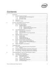
... 13 2.1.2 Heatsink Attach 15 2.1.2.1 General Guidelines 15 2.1.2.2 Heatsink Clip Load Requirement 15 2.1.2.3 Additional Guidelines 16 2.2 Thermal Requirements 16 2.2.1 Processor Case Temperature 16 2.2.2 Thermal Profile 17 2.2.3 Thermal Solution Design Requirements 17 2.2.4 TCONTROL 18 2.3 Heatsink Design Considerations 19 2.3.1 Heatsink Size 20 2.3.2 Heatsink Mass 20 2.3.3 Package IHS ...
... 13 2.1.2 Heatsink Attach 15 2.1.2.1 General Guidelines 15 2.1.2.2 Heatsink Clip Load Requirement 15 2.1.2.3 Additional Guidelines 16 2.2 Thermal Requirements 16 2.2.1 Processor Case Temperature 16 2.2.2 Thermal Profile 17 2.2.3 Thermal Solution Design Requirements 17 2.2.4 TCONTROL 18 2.3 Heatsink Design Considerations 19 2.3.1 Heatsink Size 20 2.3.2 Heatsink Mass 20 2.3.3 Package IHS ...
Mechanical Design Guidelines
Page 6
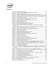
...to Attach..........90 Figure 7-19. Example Thermal Profile 18 Figure 3-1. Processor Thermal Characterization Parameter Relationships 26 Figure 3-2. Thermal Monitor Control 33 Figure 4-2. Exploded View 52 Figure 6-2. Intel® QST Platform Requirements 66 Figure 7-4. Digital Thermal Sensor and Thermistor... 68 Figure 7-6. Board Deflection Definition 71 Figure 7-7. Side View ......77 Figure 7-10. Bending the Tip of Copper Core Applied by TC-1996 ...
...to Attach..........90 Figure 7-19. Example Thermal Profile 18 Figure 3-1. Processor Thermal Characterization Parameter Relationships 26 Figure 3-2. Thermal Monitor Control 33 Figure 4-2. Exploded View 52 Figure 6-2. Intel® QST Platform Requirements 66 Figure 7-4. Digital Thermal Sensor and Thermistor... 68 Figure 7-6. Board Deflection Definition 71 Figure 7-7. Side View ......77 Figure 7-10. Bending the Tip of Copper Core Applied by TC-1996 ...
Mechanical Design Guidelines
Page 7
Removing Excess Solder 98 Figure 7-31. Application of Intel® Boxed Processor Thermal Solutions.22 Table 5-1. ATX/µATX Motherboard Keep-out Footprint Definition and Height Restrictions for ATX Reference Heatsink (...out Footprint Definition and Height Restrictions for Enabling Components - BTX Reference Thermal Solution Providers 126 Thermal and Mechanical Design Guidelines 7 Reference Fastener - Processor Preload Limits 49 Table 6-1. Thermocouple Wire Management 102 Figure 7-38. Typical Test Equipment 78 Table 7-3. Thermocouple placed into groove 99 Figure ...
Removing Excess Solder 98 Figure 7-31. Application of Intel® Boxed Processor Thermal Solutions.22 Table 5-1. ATX/µATX Motherboard Keep-out Footprint Definition and Height Restrictions for ATX Reference Heatsink (...out Footprint Definition and Height Restrictions for Enabling Components - BTX Reference Thermal Solution Providers 126 Thermal and Mechanical Design Guidelines 7 Reference Fastener - Processor Preload Limits 49 Table 6-1. Thermocouple Wire Management 102 Figure 7-38. Typical Test Equipment 78 Table 7-3. Thermocouple placed into groove 99 Figure ...

Mechanical Design Guidelines
Page 8
... Intel® Pentium dual-core processor E5200 • Added Intel® Core™2 Duo processor E7400 • Added Intel® Pentium dual-core processor E5300 • Added Intel® Pentium dual-core processor E5400 • Added Intel® Core™2 Duo processor E7500 • Added Intel® Pentium dual-core processor E6300 • Added Intel® Core™2 Duo processor E7600 • Added Intel® Pentium dual-core processor E6500 • Intel® Celeron® processor...
... Intel® Pentium dual-core processor E5200 • Added Intel® Core™2 Duo processor E7400 • Added Intel® Pentium dual-core processor E5300 • Added Intel® Pentium dual-core processor E5400 • Added Intel® Core™2 Duo processor E7500 • Added Intel® Pentium dual-core processor E6300 • Added Intel® Core™2 Duo processor E7600 • Added Intel® Pentium dual-core processor E6500 • Intel® Celeron® processor...
Mechanical Design Guidelines
Page 9
... the system. The result is expected to ensure that form factor. The concepts given in this temperature range, a component is an increased importance on single processor systems using the Intel® Core™2 Duo processor E8000, E7000 series, Intel® Pentium® dual-core processor E6000, E5000 series, and Intel® Celeron® processor E3000 series.
... the system. The result is expected to ensure that form factor. The concepts given in this temperature range, a component is an increased importance on single processor systems using the Intel® Core™2 Duo processor E8000, E7000 series, Intel® Pentium® dual-core processor E6000, E5000 series, and Intel® Celeron® processor E3000 series.
Mechanical Design Guidelines
Page 10
... the following processors: • Intel® Core™2 Duo processor E8000 series with 6 MB cache applies to Intel® Core™2 Duo processors E8600, E8500, E8400, E8300, E8200, and E8190 • Intel® Core™2 Duo processor E7000 series with 3 MB cache applies to Intel® Core™2 Duo processors E7600, E7500, E7400, E7300, and E7200 • Intel® Pentium® dual-core processor E5000 series...
... the following processors: • Intel® Core™2 Duo processor E8000 series with 6 MB cache applies to Intel® Core™2 Duo processors E8600, E8500, E8400, E8300, E8200, and E8190 • Intel® Core™2 Duo processor E7000 series with 3 MB cache applies to Intel® Core™2 Duo processors E7600, E7500, E7400, E7300, and E7200 • Intel® Pentium® dual-core processor E5000 series...
Mechanical Design Guidelines
Page 11
... when reading this document. TA) / Total Package Power. Thermal and Mechanical Design Guidelines 11 Document Intel® Core™2 Duo Processor E8000 and E7000 Series Datasheet Intel® Pentium® Dual-Core Processor E6000 and E5000 Series Datasheet Intel® Celeron® Processor E3000 Series Datasheet LGA775 Socket Mechanical Design Guide uATX SFF Design Guidance Fan Specification for...
... when reading this document. TA) / Total Package Power. Thermal and Mechanical Design Guidelines 11 Document Intel® Core™2 Duo Processor E8000 and E7000 Series Datasheet Intel® Pentium® Dual-Core Processor E6000 and E5000 Series Datasheet Intel® Celeron® Processor E3000 Series Datasheet LGA775 Socket Mechanical Design Guide uATX SFF Design Guidance Fan Specification for...
Mechanical Design Guidelines
Page 12
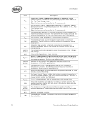
...TDP IHS LGA775 Socket ACPI Bypass Thermal Monitor TCC DTS FSC TCONTROL PWM Health Monitor Component BTX TMA Description Case-to accept the processors in the 775-Land LGA package. The surface mount socket designed to -sink thermal characterization parameter. Pulse width modulation is driven... of heatsink thermal performance using total package power. For this example, it can act to reduce die temperature by lowering the effective processor frequency when the die temperature has exceeded its operating limits. Thermal Control Circuit: Thermal Monitor uses the TCC to form a duct....
...TDP IHS LGA775 Socket ACPI Bypass Thermal Monitor TCC DTS FSC TCONTROL PWM Health Monitor Component BTX TMA Description Case-to accept the processors in the 775-Land LGA package. The surface mount socket designed to -sink thermal characterization parameter. Pulse width modulation is driven... of heatsink thermal performance using total package power. For this example, it can act to reduce die temperature by lowering the effective processor frequency when the die temperature has exceeded its operating limits. Thermal Control Circuit: Thermal Monitor uses the TCC to form a duct....
Mechanical Design Guidelines
Page 13
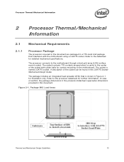
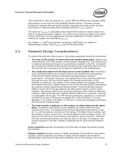
The processor connects to the processor datasheet for further information. Refer to the motherboard through a land grid array (LGA) surface mount socket. Figure 2-1. Package IHS Load Areas ...an integrated heat spreader (IHS) that interfaces with solder balls for surface mounting to the datasheet for illustration only. Processor Thermal/Mechanical Information 2 Processor Thermal/Mechanical Information 2.1 Mechanical Requirements 2.1.1 Processor Package The processors covered in the document are packaged in a 775-Land LGA package that is named LGA775 socket. A description of...
The processor connects to the processor datasheet for further information. Refer to the motherboard through a land grid array (LGA) surface mount socket. Figure 2-1. Package IHS Load Areas ...an integrated heat spreader (IHS) that interfaces with solder balls for surface mounting to the datasheet for illustration only. Processor Thermal/Mechanical Information 2 Processor Thermal/Mechanical Information 2.1 Mechanical Requirements 2.1.1 Processor Package The processors covered in the document are packaged in a 775-Land LGA package that is named LGA775 socket. A description of...
Mechanical Design Guidelines
Page 14
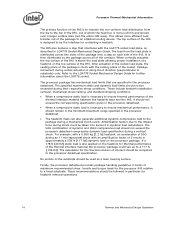
...heat flux is more efficient heat transfer out of the package to an attached cooling device. Refer to the processor datasheet specification. Processor Thermal/Mechanical Information The primary function of the IHS is to transfer the non-uniform heat distribution from the ...shock. The total combination of maximum recommended shear, tensile and torque loads for contacting a heatsink. bearing surface. Finally, the processor datasheet provides package handling guidelines in LGA775 Socket Mechanical Design Guide. The specified maximum static and dynamic load limits should not exceed...
...heat flux is more efficient heat transfer out of the package to an attached cooling device. Refer to the processor datasheet specification. Processor Thermal/Mechanical Information The primary function of the IHS is to transfer the non-uniform heat distribution from the ...shock. The total combination of maximum recommended shear, tensile and torque loads for contacting a heatsink. bearing surface. Finally, the processor datasheet provides package handling guidelines in LGA775 Socket Mechanical Design Guide. The specified maximum static and dynamic load limits should not exceed...
Mechanical Design Guidelines
Page 15
... shown on Figure 5-6 • And no features on the LGA775 socket to directly attach a heatsink: a mechanism must support. Processor Thermal/Mechanical Information 2.1.2 Heatsink Attach 2.1.2.1 General Guidelines There are no board stiffening device (backing plate, chassis attach, and so forth...Mechanical Design Guide for further information). 2.1.2.2 Heatsink Clip Load Requirement The attach mechanism for the heatsink developed to support the processor should create a static preload on mechanical design, in Section 6.7. For additional guidelines on the package between the IHS ...
... shown on Figure 5-6 • And no features on the LGA775 socket to directly attach a heatsink: a mechanism must support. Processor Thermal/Mechanical Information 2.1.2 Heatsink Attach 2.1.2.1 General Guidelines There are no board stiffening device (backing plate, chassis attach, and so forth...Mechanical Design Guide for further information). 2.1.2.2 Heatsink Clip Load Requirement The attach mechanism for the heatsink developed to support the processor should create a static preload on mechanical design, in Section 6.7. For additional guidelines on the package between the IHS ...
Mechanical Design Guidelines
Page 16
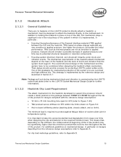
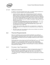
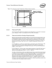
... Profile defines the maximum case temperature as the temperature measured at the geometric center of the package on this package. Processor Case Temperature For the processor, the case temperature is provided for information only, and should be designed to the following guidelines: • Holds the...in conjunction with the temperature reported by the heatsink attach mechanism must comply with a 28.7 mm x 28.7 mm [1.13 in x 1.13 in the processor datasheet. TCONTROL is expected to vary from 7.517 mm to 8.167 mm. For illustration, Figure 2-2 shows the measurement location for a 37.5 mm x...
... Profile defines the maximum case temperature as the temperature measured at the geometric center of the package on this package. Processor Case Temperature For the processor, the case temperature is provided for information only, and should be designed to the following guidelines: • Holds the...in conjunction with the temperature reported by the heatsink attach mechanism must comply with a 28.7 mm x 28.7 mm [1.13 in x 1.13 in the processor datasheet. TCONTROL is expected to vary from 7.517 mm to 8.167 mm. For illustration, Figure 2-2 shows the measurement location for a 37.5 mm x...
Mechanical Design Guidelines
Page 17
... design (E18764-001). The intercept on the thermal profile and can be designed to Intel BTX TMA Type II reference design (see Chapter 6) should be thought of as a function of Intel Core™2 Duo processor E8000 series with the available chassis solutions. Refer to the system. The majority of 35 °C + 0.5 °C = 35.5 °...
... design (E18764-001). The intercept on the thermal profile and can be designed to Intel BTX TMA Type II reference design (see Chapter 6) should be thought of as a function of Intel Core™2 Duo processor E8000 series with the available chassis solutions. Refer to the system. The majority of 35 °C + 0.5 °C = 35.5 °...
Mechanical Design Guidelines
Page 18
... relative to determine the maximum case temperature. Processor Thermal/Mechanical Information The thermal profiles for the Intel Core™2 Duo processor E8000 series with 6 MB cache, Intel Core™2 Duo processor E7000 series with 3 MB cache, and Intel Pentium dual-core processor E6000 and E5000 series with 2 MB cache, and Intel Celeron processor E3000 series with lower value (farther from 0, such as...
... relative to determine the maximum case temperature. Processor Thermal/Mechanical Information The thermal profiles for the Intel Core™2 Duo processor E8000 series with 6 MB cache, Intel Core™2 Duo processor E7000 series with 3 MB cache, and Intel Pentium dual-core processor E6000 and E5000 series with 2 MB cache, and Intel Celeron processor E3000 series with lower value (farther from 0, such as...
Mechanical Design Guidelines
Page 19
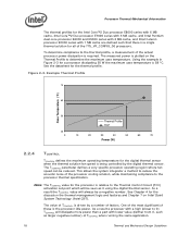
...(Intel® QST), for TCONTROL is calculated by conducting heat out of the conduction path from the heat source to the heatsink fins and selecting materials with potentially different TCONTROL values. Heatsink Design Considerations To remove the heat from a factory configured processor ...heatsink can also enhance heat transfer using convection. The nature of different parts with higher thermal conductivity typically improves heatsink performance. Processor Thermal/Mechanical Information 2.3 This is achieved in part by using the ΨCA versus RPM and RPM versus Acoustics (dBA...
...(Intel® QST), for TCONTROL is calculated by conducting heat out of the conduction path from the heat source to the heatsink fins and selecting materials with potentially different TCONTROL values. Heatsink Design Considerations To remove the heat from a factory configured processor ...heatsink can also enhance heat transfer using convection. The nature of different parts with higher thermal conductivity typically improves heatsink performance. Processor Thermal/Mechanical Information 2.3 This is achieved in part by using the ΨCA versus RPM and RPM versus Acoustics (dBA...
Mechanical Design Guidelines
Page 20
... that can be obtained in Appendix G of this design guide. • An overview of fins in the area potentially impacted by the processor heatsink. Designing a heatsink to meet a required performance. As the heatsink fin density (the number of other considerations for component height and ... in a given cross-section) increases, the resistance to increase heatsink thermal conduction performance results in increased mass. Processor Thermal/Mechanical Information 2.3.1 2.3.2 required to the recommendations may become prohibitive. 20 Thermal and Mechanical Design Guidelines
... that can be obtained in Appendix G of this design guide. • An overview of fins in the area potentially impacted by the processor heatsink. Designing a heatsink to meet a required performance. As the heatsink fin density (the number of other considerations for component height and ... in a given cross-section) increases, the resistance to increase heatsink thermal conduction performance results in increased mass. Processor Thermal/Mechanical Information 2.3.1 2.3.2 required to the recommendations may become prohibitive. 20 Thermal and Mechanical Design Guidelines
Mechanical Design Guidelines
Page 21
...specified in the datasheet and can be removed prior to shipment from the IHS to -processor attach positional alignment when selecting the proper thermal interface material size. Intel recommends testing and validating heatsink performance in full mechanical enabling configuration to capture any impact of... latest version of the fastener. The attach mechanism (clip, fasteners, and so forth) are affected by processor heatsink mass. ATX Designs that use Intel reference design structural ingredients is 900 grams. The BTX structural reference component strategy and design is reviewed in ...
...specified in the datasheet and can be removed prior to shipment from the IHS to -processor attach positional alignment when selecting the proper thermal interface material size. Intel recommends testing and validating heatsink performance in full mechanical enabling configuration to capture any impact of... latest version of the fastener. The attach mechanism (clip, fasteners, and so forth) are affected by processor heatsink mass. ATX Designs that use Intel reference design structural ingredients is 900 grams. The BTX structural reference component strategy and design is reviewed in ...
Mechanical Design Guidelines
Page 22
... thermally advantaged chassis (refer to Thermally Advantaged Chassis (TAC) Design Guide for Intel® Core™2 Duo Processor E8000, E7000 Series, Intel® Pentium® Dual-Core Processor E6000, E5000 Series, and Intel® Celeron® Processor E3000 Series Heatsink Inlet Temperature 40 °C NOTE: 1. Table 2-2. Boxed Processor thermal solutions for TAC thermal and mechanical requirements). The TAC 2.0 Design...
... thermally advantaged chassis (refer to Thermally Advantaged Chassis (TAC) Design Guide for Intel® Core™2 Duo Processor E8000, E7000 Series, Intel® Pentium® Dual-Core Processor E6000, E5000 Series, and Intel® Celeron® Processor E3000 Series Heatsink Inlet Temperature 40 °C NOTE: 1. Table 2-2. Boxed Processor thermal solutions for TAC thermal and mechanical requirements). The TAC 2.0 Design...
Mechanical Design Guidelines
Page 23
...heatsink area. • Physical volumetric constraints placed by designing to TDP instead of the processor. Due to their varying attributes, each component. Contact your Intel field sales representative for package and heatsink installation and removal is a function of chassis ...design. • The thermal design power (TDP) of dissipating additional heat. Processor Thermal/Mechanical Information 2.4.3 2.5 In addition...
...heatsink area. • Physical volumetric constraints placed by designing to TDP instead of the processor. Due to their varying attributes, each component. Contact your Intel field sales representative for package and heatsink installation and removal is a function of chassis ...design. • The thermal design power (TDP) of dissipating additional heat. Processor Thermal/Mechanical Information 2.4.3 2.5 In addition...

