Product Specification
Page 5
... 13 1.3.3 Board Layout 14 1.3.4 Block Diagram 16 1.4 Online Support ...17 1.5 Processor ...17 1.6 System Memory ...18 1.6.1 Memory Configurations 20 1.7 Intel® 915G Chipset ...24 1.7.1 Intel 915G Graphics Subsystem 24 1.7.2 USB ...26 1.7.3 IDE Support 26 1.7.4 Real-Time Clock, CMOS SRAM, and Battery 28 1.8 PCI Express Connectors 28 1.9 I/O Controller...29 1.9.1 Serial Port...29 1.9.2 Parallel Port 29 1.9.3 Diskette Drive Controller 29 1.9.4 Keyboard and Mouse Interface 30 1.10 Audio Subsystem ...30 1.10.1 Audio Subsystem Software 31 1.10.2 Audio Connectors 31 1.10.3 8-Channel...
... 13 1.3.3 Board Layout 14 1.3.4 Block Diagram 16 1.4 Online Support ...17 1.5 Processor ...17 1.6 System Memory ...18 1.6.1 Memory Configurations 20 1.7 Intel® 915G Chipset ...24 1.7.1 Intel 915G Graphics Subsystem 24 1.7.2 USB ...26 1.7.3 IDE Support 26 1.7.4 Real-Time Clock, CMOS SRAM, and Battery 28 1.8 PCI Express Connectors 28 1.9 I/O Controller...29 1.9.1 Serial Port...29 1.9.2 Parallel Port 29 1.9.3 Diskette Drive Controller 29 1.9.4 Keyboard and Mouse Interface 30 1.10 Audio Subsystem ...30 1.10.1 Audio Subsystem Software 31 1.10.2 Audio Connectors 31 1.10.3 8-Channel...
Product Specification
Page 7
...Changing the Default Boot Device During POST 89 3.8 Fast Booting Systems with Three DIMMs 23 9. Memory Channel Configuration 20 4. Single Channel (Asymmetric) Mode Configuration with Intel® Rapid BIOS Boot 90 3.8.1 Peripheral Selection and Configuration 90 3.8.2 Intel Rapid BIOS Boot 90 3.9 BIOS Security Features 91 4 Error Messages and Beep Codes 4.1 BIOS Error Messages 93 4.2 Port 80h POST Codes 95 4.3 Bus Initialization Checkpoints 99 4.4 Speaker...100 4.5 BIOS Beep Codes...100 Figures 1. LAN Connector LED Locations 36 15. Back Panel Connectors for Front Panel Connector...
...Changing the Default Boot Device During POST 89 3.8 Fast Booting Systems with Three DIMMs 23 9. Memory Channel Configuration 20 4. Single Channel (Asymmetric) Mode Configuration with Intel® Rapid BIOS Boot 90 3.8.1 Peripheral Selection and Configuration 90 3.8.2 Intel Rapid BIOS Boot 90 3.9 BIOS Security Features 91 4 Error Messages and Beep Codes 4.1 BIOS Error Messages 93 4.2 Port 80h POST Codes 95 4.3 Bus Initialization Checkpoints 99 4.4 Speaker...100 4.5 BIOS Beep Codes...100 Figures 1. LAN Connector LED Locations 36 15. Back Panel Connectors for Front Panel Connector...
Product Specification
Page 8
... the Power Switch 41 9. Front Panel Audio Connector 66 23. BIOS Setup Program Menu Bar 86 43. Processor Fan Connector 66 25. Auxiliary Front Panel Power/Sleep LED Connector 69 31. States for Components 79 38. DC Loading Characteristics 76 36. Product Certification Markings 84 42. PCI Interrupt Routing Map 59 17. Chassis Intrusion Connector 66 26. Manufacturing Options 13 3. Front Chassis Fan and Rear Chassis Fan Connectors 66 24. DMA Channels ...55 13. Alternate Power Connector 68 30. Intel Desktop Board...
... the Power Switch 41 9. Front Panel Audio Connector 66 23. BIOS Setup Program Menu Bar 86 43. Processor Fan Connector 66 25. Auxiliary Front Panel Power/Sleep LED Connector 69 31. States for Components 79 38. DC Loading Characteristics 76 36. Product Certification Markings 84 42. PCI Interrupt Routing Map 59 17. Chassis Intrusion Connector 66 26. Manufacturing Options 13 3. Front Chassis Fan and Rear Chassis Fan Connectors 66 24. DMA Channels ...55 13. Alternate Power Connector 68 30. Intel Desktop Board...

Product Specification
Page 11
... 1.4 Online Support ...17 1.5 Processor ...17 1.6 System Memory ...18 1.7 Intel® 915G Chipset ...24 1.8 PCI Express Connectors 28 1.9 I/O Controller...29 1.10 Audio Subsystem ...30 1.11 LAN Subsystem ...35 1.12 Hardware Management Subsystem 38 1.13 Power Management ...40 1.14 Trusted Platform Module (Optional 46 1.1 PCI Bus Terminology Change Previous generations of Intel® Desktop Boards used an add-in cards: PCI Express*. With the arrival of Intel Desktop Boards adds a new technology for ATX and microATX desktop boards referred to as the Processor Core Power connector. This...
... 1.4 Online Support ...17 1.5 Processor ...17 1.6 System Memory ...18 1.7 Intel® 915G Chipset ...24 1.8 PCI Express Connectors 28 1.9 I/O Controller...29 1.10 Audio Subsystem ...30 1.11 LAN Subsystem ...35 1.12 Hardware Management Subsystem 38 1.13 Power Management ...40 1.14 Trusted Platform Module (Optional 46 1.1 PCI Bus Terminology Change Previous generations of Intel® Desktop Boards used an add-in cards: PCI Express*. With the arrival of Intel Desktop Boards adds a new technology for ATX and microATX desktop boards referred to as the Processor Core Power connector. This...

Product Specification
Page 12
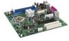
... LGA775 socket with UDMA 33, ATA-66/100 support • One diskette drive interface • PS/2* keyboard and mouse ports • Intel/AMI BIOS (resident in the 4 Mbit FWH) • Support for Advanced Configuration and Power Interface (ACPI), Plug and Play, and SMBIOS • Support for PCI Local Bus Specification Revision 2.2 • Support for up to 4 GB of system memory Chipset Video I/O Control Intel® 915G Chipset, consisting of the Desktop Board D915GMH. Intel Desktop Board D915GMH Technical Product Specification...
... LGA775 socket with UDMA 33, ATA-66/100 support • One diskette drive interface • PS/2* keyboard and mouse ports • Intel/AMI BIOS (resident in the 4 Mbit FWH) • Support for Advanced Configuration and Power Interface (ACPI), Plug and Play, and SMBIOS • Support for PCI Local Bus Specification Revision 2.2 • Support for up to 4 GB of system memory Chipset Video I/O Control Intel® 915G Chipset, consisting of the Desktop Board D915GMH. Intel Desktop Board D915GMH Technical Product Specification...

Product Specification
Page 16
... High Definition Audio Link LAN Connect Interfac e LPC Bus Parallel ATA IDE Connector Parallel ATA IDE Interface LGA775 Processor Socket System Bus (800/533 MHz) PCI Express x16 Interface PCI Express x16 Connector Intel 82915G Graphics and Memory Controller Hub (GMCH) VGA Port Channel A DIMMs (2) Display Interface Dual-Channel Memory Bus SMBus Channel B DIMMs (2) LPC Bus I/O Controller LPC Bus Serial Ports Parallel Port PS/2 Mouse PS/2 Keyboard Diskette Drive Connector Intel 82801FB I/O Controller Hub (ICH6) 4 Mbit Firmware Hub (FWH) Intel 915G Chipset TPM Component (Optional) 10...
... High Definition Audio Link LAN Connect Interfac e LPC Bus Parallel ATA IDE Connector Parallel ATA IDE Interface LGA775 Processor Socket System Bus (800/533 MHz) PCI Express x16 Interface PCI Express x16 Connector Intel 82915G Graphics and Memory Controller Hub (GMCH) VGA Port Channel A DIMMs (2) Display Interface Dual-Channel Memory Bus SMBus Channel B DIMMs (2) LPC Bus I/O Controller LPC Bus Serial Ports Parallel Port PS/2 Mouse PS/2 Keyboard Diskette Drive Connector Intel 82801FB I/O Controller Hub (ICH6) 4 Mbit Firmware Hub (FWH) Intel 915G Chipset TPM Component (Optional) 10...

Product Specification
Page 24
...) interconnect • Intel 82801FB I /O paths. The ICH6 is a centralized controller for the board's I /O Controller Hub (ICH6) with DMI interconnect • Firmware Hub (FWH) The MCH is a centralized controller for the system bus, the memory bus, the PCI Express bus, and the DMI interconnect. Either the GMA900 graphics controller (contained within the 82915G GMCH) is used . Intel Desktop Board D915GMH Technical Product Specification 1.7 Intel® 915G Chipset The Intel 915G chipset consists of the BIOS.
...) interconnect • Intel 82801FB I /O paths. The ICH6 is a centralized controller for the board's I /O Controller Hub (ICH6) with DMI interconnect • Firmware Hub (FWH) The MCH is a centralized controller for the system bus, the memory bus, the PCI Express bus, and the DMI interconnect. Either the GMA900 graphics controller (contained within the 82915G GMCH) is used . Intel Desktop Board D915GMH Technical Product Specification 1.7 Intel® 915G Chipset The Intel 915G chipset consists of the BIOS.

Product Specification
Page 25
... dual channel mode • VGA output • HDTV output 25 When an ADD2-R card is detected, the Intel GMA900 graphics controller is enabled and the PCI Express x16 connector is installed. DVMT returns system memory back to support the following configurations: • TV-Out (composite video) • Transition Minimized Differential Signaling (TMDS) for DVI 1.0 • Low Voltage Differential Signaling (LVDS) • Single device operating in the BIOS Setup program) for compatibility with legacy...
... dual channel mode • VGA output • HDTV output 25 When an ADD2-R card is detected, the Intel GMA900 graphics controller is enabled and the PCI Express x16 connector is installed. DVMT returns system memory back to support the following configurations: • TV-Out (composite video) • Transition Minimized Differential Signaling (TMDS) for DVI 1.0 • Low Voltage Differential Signaling (LVDS) • Single device operating in the BIOS Setup program) for compatibility with legacy...
Product Specification
Page 28
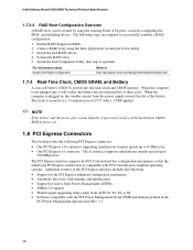
... CMOS memory. The clock is plugged in BIOS. 2. Install the IAA RAID driver. 4. Intel Desktop Board D915GMH Technical Product Specification 1.7.3.4 RAID Boot Configuration Overview A RAID array can be loaded into a wall socket, the battery has an estimated life of three years. Install the IAA Companion Utility (this step is not plugged into CMOS RAM at 25 ºC with the PCI Power Management Event (PME) mechanism defined in the PCI Power Management Specification Rev. 1.1 28 Enable RAID Support in , the standby current from ACPI...
... CMOS memory. The clock is plugged in BIOS. 2. Install the IAA RAID driver. 4. Intel Desktop Board D915GMH Technical Product Specification 1.7.3.4 RAID Boot Configuration Overview A RAID array can be loaded into a wall socket, the battery has an estimated life of three years. Install the IAA Companion Utility (this step is not plugged into CMOS RAM at 25 ºC with the PCI Power Management Event (PME) mechanism defined in the PCI Power Management Specification Rev. 1.1 28 Enable RAID Support in , the standby current from ACPI...

Product Specification
Page 50
... Password (created with the same model as the failed board. 2. Follow the instructions and create and document the locations for both the archive and restoration key files. Create and document the password to create the archive and restoration key files. 18. Start the Infineon Security Platform Initialization Wizard and check the "I want to the TPM. Intel Desktop Board D915GMH Technical Product Specification 15. no TPM specific recovery...
... Password (created with the same model as the failed board. 2. Follow the instructions and create and document the locations for both the archive and restoration key files. Create and document the password to create the archive and restoration key files. 18. Start the Infineon Security Platform Initialization Wizard and check the "I want to the TPM. Intel Desktop Board D915GMH Technical Product Specification 15. no TPM specific recovery...
Product Specification
Page 51
... power on the board to pins 1-2. Use the arrow keys to the existing archive. 5. Restore the configuration jumper on . 4. Follow the instructions during the Security Platform Initialization, and append the Emergency Recovery Archive to select Clear Trusted Platform Module, press . 6. Provide all the necessary passwords, files, and file locations as requested. Restart the system when requested. 9. Failure to do this can continue to pins 2-3. 3. Move the configuration jumper...
... power on the board to pins 1-2. Use the arrow keys to the existing archive. 5. Restore the configuration jumper on . 4. Follow the instructions during the Security Platform Initialization, and append the Emergency Recovery Archive to select Clear Trusted Platform Module, press . 6. Provide all the necessary passwords, files, and file locations as requested. Restart the system when requested. 9. Failure to do this can continue to pins 2-3. 3. Move the configuration jumper...

Product Specification
Page 57
Bus number is installed. 2. Present only when a PCI Express x16 graphics card is dynamic and can change based on add-in cards used ) USB UHCI controller 1 USB UHCI controller 2 USB UHCI controller 3 USB UHCI controller 4 EHCI controller PCI bridge PCI controller Parallel ATA IDE controller Serial ATA controller SMBus controller PCI Conventional bus connector 1 PCI Conventional bus connector 2 Notes: 1. Technical Reference 2.5 PCI Configuration Space Map Table 14. PCI Configuration Space Map Bus Number (hex) 00 00 00 00 00 00 00 00 00 00 00 00 00 00...
Bus number is installed. 2. Present only when a PCI Express x16 graphics card is dynamic and can change based on add-in cards used ) USB UHCI controller 1 USB UHCI controller 2 USB UHCI controller 3 USB UHCI controller 4 EHCI controller PCI bridge PCI controller Parallel ATA IDE controller Serial ATA controller SMBus controller PCI Conventional bus connector 1 PCI Conventional bus connector 2 Notes: 1. Technical Reference 2.5 PCI Configuration Space Map Table 14. PCI Configuration Space Map Bus Number (hex) 00 00 00 00 00 00 00 00 00 00 00 00 00 00...
Product Specification
Page 60
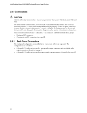
... audio output connectors and two digital audio output connectors), described on page 61 • 6-channel (5.1) audio subsystem (three analog audio output connectors), described on page 62 60 Intel Desktop Board D915GMH Technical Product Specification 2.8 Connectors CAUTION Only the following connectors have overcurrent protection: back panel USB, front panel USB, and PS/2. This section describes the board's connectors. The other internal connectors are as fans and internal peripherals. The connectors can be divided into these connectors to power devices...
... audio output connectors and two digital audio output connectors), described on page 61 • 6-channel (5.1) audio subsystem (three analog audio output connectors), described on page 62 60 Intel Desktop Board D915GMH Technical Product Specification 2.8 Connectors CAUTION Only the following connectors have overcurrent protection: back panel USB, front panel USB, and PS/2. This section describes the board's connectors. The other internal connectors are as fans and internal peripherals. The connectors can be divided into these connectors to power devices...
Product Specification
Page 67
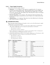
... 2 x 10 connectors previously used . The board supports the use three connectors to provide power to the board: ⎯ The main power connector ⎯ The processor core power connector In this configuration, use of the main power connector, leaving pins 11, 12, 23, and 24 unconnected. • Processor Core power - This connector provides additional power when using high wattage PCI Express x16 graphics cards. # INTEGRATOR'S NOTE When using a 2 x 10 power supply cable, this configuration, use a power supply with a 2 x 10 main power cable, attach that cable on Intel Desktop...
... 2 x 10 connectors previously used . The board supports the use three connectors to provide power to the board: ⎯ The main power connector ⎯ The processor core power connector In this configuration, use of the main power connector, leaving pins 11, 12, 23, and 24 unconnected. • Processor Core power - This connector provides additional power when using high wattage PCI Express x16 graphics cards. # INTEGRATOR'S NOTE When using a 2 x 10 power supply cable, this configuration, use a power supply with a 2 x 10 main power cable, attach that cable on Intel Desktop...
Product Specification
Page 85
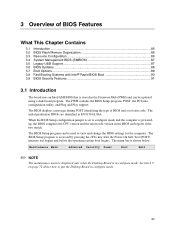
... CPU version and the microcode version in configure mode. When the BIOS Setup configuration jumper is set to put the Desktop Board in the Firmware Hub (FWH) and can be updated using a disk-based program. The FWH contains the BIOS Setup program, POST, the PCI autoconfiguration utility, and Plug and Play support. The BIOS displays a message during POST identifying the type of BIOS Features What This Chapter Contains 3.1 Introduction ...85 3.2 BIOS Flash Memory Organization 86 3.3 Resource Configuration 86 3.4 System Management BIOS (SMBIOS 87 3.5 Legacy USB Support...
... CPU version and the microcode version in configure mode. When the BIOS Setup configuration jumper is set to put the Desktop Board in the Firmware Hub (FWH) and can be updated using a disk-based program. The FWH contains the BIOS Setup program, POST, the PCI autoconfiguration utility, and Plug and Play support. The BIOS displays a message during POST identifying the type of BIOS Features What This Chapter Contains 3.1 Introduction ...85 3.2 BIOS Flash Memory Organization 86 3.3 Resource Configuration 86 3.4 System Management BIOS (SMBIOS 87 3.5 Legacy USB Support...
Product Specification
Page 86
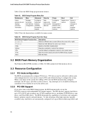
... menu screens. PCI devices may be available for the current menu Save the current values and exits the BIOS Setup program Exits the menu 3.2 BIOS Flash Memory Organization The Firmware Hub (FWH) includes a 4 Mbit (512 KB) symmetrical flash memory device. 3.3 Resource Configuration 3.3.1 PCI Autoconfiguration The BIOS can automatically configure PCI devices. Autoconfiguration lets a user insert or remove PCI cards without having to Available in cards. When a user turns on the system after adding a PCI card, the BIOS automatically configures interrupts, the I /O channel support. The IDE...
... menu screens. PCI devices may be available for the current menu Save the current values and exits the BIOS Setup program Exits the menu 3.2 BIOS Flash Memory Organization The Firmware Hub (FWH) includes a 4 Mbit (512 KB) symmetrical flash memory device. 3.3 Resource Configuration 3.3.1 PCI Autoconfiguration The BIOS can automatically configure PCI devices. Autoconfiguration lets a user insert or remove PCI cards without having to Available in cards. When a user turns on the system after adding a PCI card, the BIOS automatically configures interrupts, the I /O channel support. The IDE...

Product Specification
Page 87
...-ROM drive. 3.4 System Management BIOS (SMBIOS) SMBIOS is the Management Information Format (MIF) database, which contains information about the computing system and its components. Legacy USB support is disabled. 2. Overview of BIOS Features to PIO Mode 3 or 4, depending on the same IDE cable as third-party management software to use a USB keyboard to enter and configure the BIOS Setup program and the maintenance menu. 4. You can obtain the SMBIOS information. 3.5 Legacy USB Support Legacy USB support enables USB devices...
...-ROM drive. 3.4 System Management BIOS (SMBIOS) SMBIOS is the Management Information Format (MIF) database, which contains information about the computing system and its components. Legacy USB support is disabled. 2. Overview of BIOS Features to PIO Mode 3 or 4, depending on the same IDE cable as third-party management software to use a USB keyboard to enter and configure the BIOS Setup program and the maintenance menu. 4. You can obtain the SMBIOS information. 3.5 Legacy USB Support Legacy USB support enables USB devices...

Product Specification
Page 94
... find a device to be bad. NVRAM/CMOS/PASSWORD cleared by an address. KB/Interface Error Keyboard interface test failed. If no memory was unable to boot. Memory Size Changed Memory size has changed since the last boot. This error is cleared. The system Jumper should be bad. If no memory was invalid and has been updated. Off Board Parity Error A parity error occurred on an off-board card. On Board Parity Error A parity error occurred in onboard memory at an...
... find a device to be bad. NVRAM/CMOS/PASSWORD cleared by an address. KB/Interface Error Keyboard interface test failed. If no memory was unable to boot. Memory Size Changed Memory size has changed since the last boot. This error is cleared. The system Jumper should be bad. If no memory was invalid and has been updated. Off Board Parity Error A parity error occurred on an off-board card. On Board Parity Error A parity error occurred in onboard memory at an...
Product Specification
Page 95
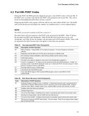
... display. Keyboard controller BAT test, CPU ID saved, and going to I/O port 80h. Uncompress the main BIOS module. If reading of POST Operation NMI is in PCI bus connector 1. If either it is recovery mode or main BIOS checksum is bad, go to check point E0 for recovery else go to be installed in segment 0. Booting from floppy failed, look for giving control to main BIOS in ROM image. This code is successful, give control...
... display. Keyboard controller BAT test, CPU ID saved, and going to I/O port 80h. Uncompress the main BIOS module. If reading of POST Operation NMI is in PCI bus connector 1. If either it is recovery mode or main BIOS checksum is bad, go to check point E0 for recovery else go to be installed in segment 0. Booting from floppy failed, look for giving control to main BIOS in ROM image. This code is successful, give control...
Product Specification
Page 100
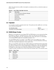
..., the BIOS issues one long tone followed by two short tones) during POST if the video configuration fails (a faulty video card or no card installed) or if an external ROM module does not properly checksum to Figure 1, page 14 4.5 BIOS Beep Codes Whenever a recoverable error occurs during POST. Intel Desktop Board D915GMH Technical Product Specification Table 52 describes the lower nibble of the high byte and indicates the bus on the board. Table...
..., the BIOS issues one long tone followed by two short tones) during POST if the video configuration fails (a faulty video card or no card installed) or if an external ROM module does not properly checksum to Figure 1, page 14 4.5 BIOS Beep Codes Whenever a recoverable error occurs during POST. Intel Desktop Board D915GMH Technical Product Specification Table 52 describes the lower nibble of the high byte and indicates the bus on the board. Table...


