Product Specification
Page 5
... Online Support ...17 1.5 Processor ...17 1.6 System Memory ...18 1.6.1 Memory Configurations 20 1.7 Intel® 915G Chipset ...24 1.7.1 Intel 915G Graphics Subsystem 24 1.7.2 USB ...26 1.7.3 IDE Support 26 1.7.4 Real-Time Clock, CMOS SRAM, and Battery 28 1.8 PCI Express Connectors 28 1.9 I/O Controller...Interface 30 1.10 Audio Subsystem ...30 1.10.1 Audio Subsystem Software 31 1.10.2 Audio Connectors 31 1.10.3 8-Channel (7.1) Audio Subsystem 32 1.10.4 6-Channel (5.1) Audio Subsystem 34 1.11 LAN Subsystem ...35 1.11.1 10/100 Mbits/sec LAN Subsystem 35 1.11.2 Gigabit LAN Subsystem 36...
... Online Support ...17 1.5 Processor ...17 1.6 System Memory ...18 1.6.1 Memory Configurations 20 1.7 Intel® 915G Chipset ...24 1.7.1 Intel 915G Graphics Subsystem 24 1.7.2 USB ...26 1.7.3 IDE Support 26 1.7.4 Real-Time Clock, CMOS SRAM, and Battery 28 1.8 PCI Express Connectors 28 1.9 I/O Controller...Interface 30 1.10 Audio Subsystem ...30 1.10.1 Audio Subsystem Software 31 1.10.2 Audio Connectors 31 1.10.3 8-Channel (7.1) Audio Subsystem 32 1.10.4 6-Channel (5.1) Audio Subsystem 34 1.11 LAN Subsystem ...35 1.11.1 10/100 Mbits/sec LAN Subsystem 35 1.11.2 Gigabit LAN Subsystem 36...
Product Specification
Page 8
...Power States and Targeted System Power 41 10. DMA Channels ...55 13. Interrupts ...58 16. Component-side Connectors Shown in Figure 1 15 4. Processor Fan Connector 66 25. Main Power... Connector 67 28. Fan Connector Current Capability 76 37. Product Certification Markings 84 42. Manufacturing Options 13 3. LAN Connector LED States 37 8. PCI Interrupt ...11. Processor Core Power Connector 68 29. ATAPI CD-ROM Connector (Optional 65 22. Front Panel Audio Connector 66 23. EMC Regulations ...81 41. Intel Desktop Board...
...Power States and Targeted System Power 41 10. DMA Channels ...55 13. Interrupts ...58 16. Component-side Connectors Shown in Figure 1 15 4. Processor Fan Connector 66 25. Main Power... Connector 67 28. Fan Connector Current Capability 76 37. Product Certification Markings 84 42. Manufacturing Options 13 3. LAN Connector LED States 37 8. PCI Interrupt ...11. Processor Core Power Connector 68 29. ATAPI CD-ROM Connector (Optional 65 22. Front Panel Audio Connector 66 23. EMC Regulations ...81 41. Intel Desktop Board...

Product Specification
Page 11
...://www.formfactors.org 11 1 Product Description What This Chapter Contains 1.1 PCI Bus Terminology Change 11 1.2 Power Connector Terminology Change 11 1.3 Overview ...12 1.4 Online Support ...17 1.5 Processor ...17 1.6 System Memory ...18 1.7 Intel® 915G Chipset ...24 1.8 PCI Express Connectors 28 1.9 I/O Controller...29 1.10 Audio Subsystem ...30 1.11 LAN Subsystem ...35 1.12 Hardware Management Subsystem 38 1.13 Power Management...
...://www.formfactors.org 11 1 Product Description What This Chapter Contains 1.1 PCI Bus Terminology Change 11 1.2 Power Connector Terminology Change 11 1.3 Overview ...12 1.4 Online Support ...17 1.5 Processor ...17 1.6 System Memory ...18 1.7 Intel® 915G Chipset ...24 1.8 PCI Express Connectors 28 1.9 I/O Controller...29 1.10 Audio Subsystem ...30 1.11 LAN Subsystem ...35 1.12 Hardware Management Subsystem 38 1.13 Power Management...

Product Specification
Page 12
... for PCI Express Revision 1.0a • Suspend to 4 GB of system memory Chipset Video I/O Control Intel® 915G Chipset, consisting of the Desktop Board D915GMH. Feature Summary Form Factor Processor Memory microBTX Form Factor (10.50 inches by 10.40 inches [266.70 millimeters by 264.16 millimeters]) Support for an Intel® Pentium® 4 processor in an LGA775...
... for PCI Express Revision 1.0a • Suspend to 4 GB of system memory Chipset Video I/O Control Intel® 915G Chipset, consisting of the Desktop Board D915GMH. Feature Summary Form Factor Processor Memory microBTX Form Factor (10.50 inches by 10.40 inches [266.70 millimeters by 264.16 millimeters]) Support for an Intel® Pentium® 4 processor in an LGA775...

Product Specification
Page 15
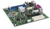
...the components identified in card connectors PCI Express x16 connector Alternate power connector (1 x 4) Diskette drive connector BIOS Setup Configuration Jumper IEEE 1394a connectors (optional) Front chassis fan connector Front panel connector Alternate power LED connector Processor socket Processor core power connector (2 x 2) Processor fan header (4-pin, fan speed ... 1 A B C D E F G H I J K L M N O P Q R S T U V W X Description Front panel audio connector Chassis intrusion connector Main power connector (2 x 12) Front Panel USB connectors PCI Express x1 connector PCI bus add-in Figure 1.
...the components identified in card connectors PCI Express x16 connector Alternate power connector (1 x 4) Diskette drive connector BIOS Setup Configuration Jumper IEEE 1394a connectors (optional) Front chassis fan connector Front panel connector Alternate power LED connector Processor socket Processor core power connector (2 x 2) Processor fan header (4-pin, fan speed ... 1 A B C D E F G H I J K L M N O P Q R S T U V W X Description Front panel audio connector Chassis intrusion connector Main power connector (2 x 12) Front Panel USB connectors PCI Express x1 connector PCI bus add-in Figure 1.

Product Specification
Page 16
...LAN Connect Interfac e LPC Bus Parallel ATA IDE Connector Parallel ATA IDE Interface LGA775 Processor Socket System Bus (800/533 MHz) PCI Express x16 Interface PCI Express x16 Connector Intel 82915G Graphics and Memory Controller Hub (GMCH) VGA Port Channel A DIMMs (2) Display Interface Dual...Drive Connector Intel 82801FB I/O Controller Hub (ICH6) 4 Mbit Firmware Hub (FWH) Intel 915G Chipset TPM Component (Optional) 10/100 LAN PLC (Optional) LAN Connector IEEE-1394a Connectors (Optional) PCI Bus PCI Bus Serial ATA IDE Interface Serial ATA IDE Connectors (4) PCI Slot 1 PCI Slot 2...
...LAN Connect Interfac e LPC Bus Parallel ATA IDE Connector Parallel ATA IDE Interface LGA775 Processor Socket System Bus (800/533 MHz) PCI Express x16 Interface PCI Express x16 Connector Intel 82915G Graphics and Memory Controller Hub (GMCH) VGA Port Channel A DIMMs (2) Display Interface Dual...Drive Connector Intel 82801FB I/O Controller Hub (ICH6) 4 Mbit Firmware Hub (FWH) Intel 915G Chipset TPM Component (Optional) 10/100 LAN PLC (Optional) LAN Connector IEEE-1394a Connectors (Optional) PCI Bus PCI Bus Serial ATA IDE Interface Serial ATA IDE Connectors (4) PCI Slot 1 PCI Slot 2...

Product Specification
Page 17
... http://developer.intel.com/design/chipsets/datashts http://intel.com/design/motherbd/gen_indx.htm http://www.intel.com/design/motherbd http://www.intel.com/design/motherbd 1.5 Processor The board is designed to support Intel Pentium 4 processors in damage to the board and/or the power supply. • Refer to the board may result in an LGA775 processor socket with...
... http://developer.intel.com/design/chipsets/datashts http://intel.com/design/motherbd/gen_indx.htm http://www.intel.com/design/motherbd http://www.intel.com/design/motherbd 1.5 Processor The board is designed to support Intel Pentium 4 processors in damage to the board and/or the power supply. • Refer to the board may result in an LGA775 processor socket with...

Product Specification
Page 18
...minimizes system latencies to accurately configure memory settings for information on the total amount of DIMM... Intel Desktop Board D915GMH Technical Product Specification 1.6 System Memory The board has four DIMM sockets and support ... structure. Table 4. DDR 400 DDR 333 (Note) The processor's system bus frequency must be... 800 MHz 800 or 533 MHz Note: When using ...lists the supported system bus frequency and memory speed combinations. NOTES • Remove the PCI Express x16 video card before installing or upgrading memory to correctly configure the memory settings, ...
...minimizes system latencies to accurately configure memory settings for information on the total amount of DIMM... Intel Desktop Board D915GMH Technical Product Specification 1.6 System Memory The board has four DIMM sockets and support ... structure. Table 4. DDR 400 DDR 333 (Note) The processor's system bus frequency must be... 800 MHz 800 or 533 MHz Note: When using ...lists the supported system bus frequency and memory speed combinations. NOTES • Remove the PCI Express x16 video card before installing or upgrading memory to correctly configure the memory settings, ...

Product Specification
Page 26
...an unshielded cable attached to a USB port may not meet FCC Class B requirements, even if no device is attached to the cable. Intel Desktop Board D915GMH Technical Product Specification NOTE This board supports ADD2-R cards only. For information about The location of the USB connectors on IDE...• 8237-style DMA: DMA offloads the processor, supporting transfer rates of up to 16 MB/sec. • Ultra DMA: DMA protocol on IDE bus supporting host and target throttling and transfer rates of ADD2 cards are not compatible with dual stacked back panel connectors adjacent to the serial...
...an unshielded cable attached to a USB port may not meet FCC Class B requirements, even if no device is attached to the cable. Intel Desktop Board D915GMH Technical Product Specification NOTE This board supports ADD2-R cards only. For information about The location of the USB connectors on IDE...• 8237-style DMA: DMA offloads the processor, supporting transfer rates of up to 16 MB/sec. • Ultra DMA: DMA protocol on IDE bus supporting host and target throttling and transfer rates of ADD2 cards are not compatible with dual stacked back panel connectors adjacent to the serial...

Product Specification
Page 37
... The boards provide the following ASF support for the onboard 10/100/1000 LAN subsystem, PCI Express x1 bus add-in LAN cards, and PCI Conventional bus add-in LAN cards installed in PCI Conventional bus slot 2: • Monitoring of system firmware progress events, including: ⎯ BIOS present ⎯ Primary processor initialization ⎯ Memory initialization ⎯ Video initialization ⎯...
... The boards provide the following ASF support for the onboard 10/100/1000 LAN subsystem, PCI Express x1 bus add-in LAN cards, and PCI Conventional bus add-in LAN cards installed in PCI Conventional bus slot 2: • Monitoring of system firmware progress events, including: ⎯ BIOS present ⎯ Primary processor initialization ⎯ Memory initialization ⎯ Video initialization ⎯...
Product Specification
Page 38
... monitoring and fan control ASIC include: • Internal ambient temperature sensor • Two remote thermal diode sensors for direct monitoring of processor temperature and ambient temperature sensing • Power supply monitoring of the fan connectors and sensors for thermal monitoring Refer to be compatible with...the fan speed or switch the fans on or off as needed • SMBus interface For information about Refer to Obtaining LAN software and drivers Section 1.4, page 17 1.12 Hardware Management Subsystem The hardware management features enable the board to Figure 15, page ...
... monitoring and fan control ASIC include: • Internal ambient temperature sensor • Two remote thermal diode sensors for direct monitoring of processor temperature and ambient temperature sensing • Power supply monitoring of the fan connectors and sensors for thermal monitoring Refer to be compatible with...the fan speed or switch the fans on or off as needed • SMBus interface For information about Refer to Obtaining LAN software and drivers Section 1.4, page 17 1.12 Hardware Management Subsystem The hardware management features enable the board to Figure 15, page ...

Product Specification
Page 39
Product Description E B Intel R 82801 (ICH) Intel R 82915G (GMCH) C D A F Item A B C D E F Description Thermal diode, located on processor die Remote ambient temperature sensor Ambient temperature sensor, internal to hardware monitoring and fan control ASIC Processor fan Rear chassis fan Front chassis fan Figure 15. 1.12.2 Thermal Monitoring Figure 15 shows the location of the sensors and fan connectors. Thermal Monitoring OM17546 39
Product Description E B Intel R 82801 (ICH) Intel R 82915G (GMCH) C D A F Item A B C D E F Description Thermal diode, located on processor die Remote ambient temperature sensor Ambient temperature sensor, internal to hardware monitoring and fan control ASIC Processor fan Rear chassis fan Front chassis fan Figure 15. 1.12.2 Thermal Monitoring Figure 15 shows the location of the sensors and fan connectors. Thermal Monitoring OM17546 39

Product Specification
Page 41
... associated system power targets. Soft off ) On (ACPI G0 - Devices that are being used by the system chassis' power supply. 2. working state) On (ACPI G0 - Processor stopped S3 - S5 - working C1 - no power except for wake-up (ACPI G0 - Power States and Targeted System Power Global States G0 - no power for...
... associated system power targets. Soft off ) On (ACPI G0 - Devices that are being used by the system chassis' power supply. 2. working state) On (ACPI G0 - Processor stopped S3 - S5 - working C1 - no power except for wake-up (ACPI G0 - Power States and Targeted System Power Global States G0 - no power for...

Product Specification
Page 43
.... For information about The location of the fan connectors The location of the fan connectors and sensors for thermal monitoring The signal names of the processor fan connector The signal names of the chassis fan connectors Refer to Figure 20, page 64 Figure 15, page 39 Table 24, page 66 Table...
.... For information about The location of the fan connectors The location of the fan connectors and sensors for thermal monitoring The signal names of the processor fan connector The signal names of the chassis fan connectors Refer to Figure 20, page 64 Figure 15, page 39 Table 24, page 66 Table...

Product Specification
Page 66
Intel Desktop Board D915GMH Technical Product Specification Table 22. Front Chassis Fan and Rear Chassis Fan Connectors Pin Signal Name 1 Control 2 +12 V 3 Tach Table 24. Serial ATA Connectors Pin Signal Name 1 Ground 2 TXP 3 TXN 4 Ground 5 RXN 6 RXP 7 Ground 66 Processor Fan Connector Pin Signal...Port 2] Left Channel Pin Signal Name 2 Ground 4 Presence# (dongle present) 6 Port E [Port 1] Sense return (jack detection) 8 Key 10 Port F [Port 2] Sense return (jack detection) # INTEGRATOR'S NOTE The front panel audio connector is colored yellow.
Intel Desktop Board D915GMH Technical Product Specification Table 22. Front Chassis Fan and Rear Chassis Fan Connectors Pin Signal Name 1 Control 2 +12 V 3 Tach Table 24. Serial ATA Connectors Pin Signal Name 1 Ground 2 TXP 3 TXN 4 Ground 5 RXN 6 RXP 7 Ground 66 Processor Fan Connector Pin Signal...Port 2] Left Channel Pin Signal Name 2 Ground 4 Presence# (dongle present) 6 Port E [Port 1] Sense return (jack detection) 8 Key 10 Port F [Port 2] Sense return (jack detection) # INTEGRATOR'S NOTE The front panel audio connector is colored yellow.
Product Specification
Page 67
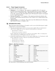
...supply connectors: • Main power - When using a power supply with a 2 x 10 main power cable, attach that cable on Intel Desktop boards. Failure to the processor voltage regulator and must always be unconnected. 67 The 2 x 12 main power cable ... Ground (Note) Note: When using high wattage PCI Express x16 graphics cards, use a power supply with 2 x 10 connectors previously used . This connector provides additional power when using high wattage PCI Express x16 graphics cards. # INTEGRATOR'S NOTE When using a 2 x 10 power supply cable, this configuration, the alternate power...
...supply connectors: • Main power - When using a power supply with a 2 x 10 main power cable, attach that cable on Intel Desktop boards. Failure to the processor voltage regulator and must always be unconnected. 67 The 2 x 12 main power cable ... Ground (Note) Note: When using high wattage PCI Express x16 graphics cards, use a power supply with 2 x 10 connectors previously used . This connector provides additional power when using high wattage PCI Express x16 graphics cards. # INTEGRATOR'S NOTE When using a 2 x 10 power supply cable, this configuration, the alternate power...
Product Specification
Page 68
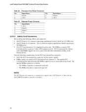
... line is routed to pin A41. Note the following add-in cards with SMBus support to support only a PCI Express x1 link when the Intel GMA900 graphics controller is enabled. 68 The x1 interfaces support simultaneous transfer speeds up to 500 MBytes/sec • ...connectors: • One PCI Express x16 connector supporting simultaneous transfer speeds up to 8 GBytes/sec • One PCI Express x1 connector. This enables PCI Conventional bus add-in boards with SMBus support can access sensor data and other information residing on the board. Processor Core Power Connector Pin Signal...
... line is routed to pin A41. Note the following add-in cards with SMBus support to support only a PCI Express x1 link when the Intel GMA900 graphics controller is enabled. 68 The x1 interfaces support simultaneous transfer speeds up to 500 MBytes/sec • ...connectors: • One PCI Express x16 connector supporting simultaneous transfer speeds up to 8 GBytes/sec • One PCI Express x1 connector. This enables PCI Conventional bus add-in boards with SMBus support can access sensor data and other information residing on the board. Processor Core Power Connector Pin Signal...

Product Specification
Page 72
... recover the BIOS configuration. Configure 2-3 3 1 After the POST runs, Setup runs automatically. Table 34 describes the jumper settings for booting. Intel Desktop Board D915GMH Technical Product Specification 2.9 Jumper Block CAUTION Do not move the jumper with the power on. The maintenance menu is poweredup,... the BIOS compares the processor version and the microcode version in the BIOS and reports if the two match. 3 1 Figure 24. Always turn off the power...
... recover the BIOS configuration. Configure 2-3 3 1 After the POST runs, Setup runs automatically. Table 34 describes the jumper settings for booting. Intel Desktop Board D915GMH Technical Product Specification 2.9 Jumper Block CAUTION Do not move the jumper with the power on. The maintenance menu is poweredup,... the BIOS compares the processor version and the microcode version in the BIOS and reports if the two match. 3 1 Figure 24. Always turn off the power...

Product Specification
Page 76
... A 16.00 A 0.10 A +5 VSB 0.80 A 1.40 A 2.11.2 Add-in Board Considerations The board is designed to provide 2 A (average) of all three expansion slots and the PCI Express x16 slot filled) must not exceed 8 A. 2.11.3 Fan Connector Current Capability CAUTION The processor fan must be connected to the processor fan connector, not to the processor, memory, and...
... A 16.00 A 0.10 A +5 VSB 0.80 A 1.40 A 2.11.2 Add-in Board Considerations The board is designed to provide 2 A (average) of all three expansion slots and the PCI Express x16 slot filled) must not exceed 8 A. 2.11.3 Fan Connector Current Capability CAUTION The processor fan must be connected to the processor fan connector, not to the processor, memory, and...

Product Specification
Page 77
... Considerations CAUTION A chassis with adequate thermal performance. CAUTION Failure to ensure appropriate airflow may result in damage to the board. Intel makes no warranties or representations that merely following the instructions presented in Table 35 when selecting a power supply for use with ...case temperature and malfunction. Additional power required will result in a system with a maximum internal ambient temperature of 38 oC at the processor fan inlet is maintained in damage to the board. All responsibility for the power supply must be capable of providing adequate +5 ...
... Considerations CAUTION A chassis with adequate thermal performance. CAUTION Failure to ensure appropriate airflow may result in damage to the board. Intel makes no warranties or representations that merely following the instructions presented in Table 35 when selecting a power supply for use with ...case temperature and malfunction. Additional power required will result in a system with a maximum internal ambient temperature of 38 oC at the processor fan inlet is maintained in damage to the board. All responsibility for the power supply must be capable of providing adequate +5 ...


