Product Specification
Page 5
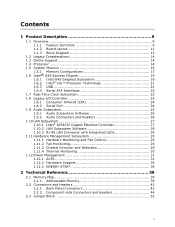
... 9 1.1 Overview 9 1.1.1 Feature Summary 9 1.1.2 Board Layout 11 1.1.3 Block Diagram 13 1.2 Legacy Considerations 14 1.3 Online Support 14 1.4 Processor 14 1.5 System Memory 16 1.5.1 Memory Configurations 17 1.6 Intel® G45 Express Chipset 19 1.6.1 Intel G45 Graphics Subsystem 19 1.6.2 Intel® Viiv™ Processor Technology 21 1.6.3 USB 21 1.6.4 Serial ATA Interfaces 22 1.7 Real-Time Clock Subsystem 23 1.8 Legacy I/O Controller 23...
... 9 1.1 Overview 9 1.1.1 Feature Summary 9 1.1.2 Board Layout 11 1.1.3 Block Diagram 13 1.2 Legacy Considerations 14 1.3 Online Support 14 1.4 Processor 14 1.5 System Memory 16 1.5.1 Memory Configurations 17 1.6 Intel® G45 Express Chipset 19 1.6.1 Intel G45 Graphics Subsystem 19 1.6.2 Intel® Viiv™ Processor Technology 21 1.6.3 USB 21 1.6.4 Serial ATA Interfaces 22 1.7 Real-Time Clock Subsystem 23 1.8 Legacy I/O Controller 23...
Product Specification
Page 7
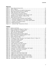
...vii Contents Figures Figure 1. Back Panel Connectors 43 Figure 10. LAN Connector LED States 28 Table 6. Chassis Intrusion Header 46 Table 15. Processor (4-Pin) Fan Header 47 Table 17. Main Power Connector 49 Table 22. Recommended Power Supply Current Values 56 Table 27. Component-side ... Front Panel Power/Sleep LED Header 48 Table 20. LAN Connector LED Locations 28 Figure 6. Wake-up Devices and Events 33 Table 9. Processor Core Power Connector 49 Table 21. Major Board Components 11 Figure 2. Front Panel Audio Header 46 Table 12. Serial Port Header 46 Table...
...vii Contents Figures Figure 1. Back Panel Connectors 43 Figure 10. LAN Connector LED States 28 Table 6. Chassis Intrusion Header 46 Table 15. Processor (4-Pin) Fan Header 47 Table 17. Main Power Connector 49 Table 22. Recommended Power Supply Current Values 56 Table 27. Component-side ... Front Panel Power/Sleep LED Header 48 Table 20. LAN Connector LED Locations 28 Figure 6. Wake-up Devices and Events 33 Table 9. Processor Core Power Connector 49 Table 21. Major Board Components 11 Figure 2. Front Panel Audio Header 46 Table 12. Serial Port Header 46 Table...
Product Specification
Page 9
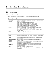
... millimeters by 171.45 millimeters]) Processor Memory Chipset Support for the following: • Intel® Core™2 Duo processor in an LGA775 socket • Intel® Pentium® Dual-Core processor in an LGA775 socket • Intel® Celeron® Dual-Core processor in an LGA775 socket • Intel® Celeron® processor Sequence 400 in an LGA775 socket...
... millimeters by 171.45 millimeters]) Processor Memory Chipset Support for the following: • Intel® Core™2 Duo processor in an LGA775 socket • Intel® Pentium® Dual-Core processor in an LGA775 socket • Intel® Celeron® Dual-Core processor in an LGA775 socket • Intel® Celeron® processor Sequence 400 in an LGA775 socket...
Product Specification
Page 14
... -date list of supported processors. The processors listed above . Supported processors Refer to support processors with specific changes including (but not limited to) the following processors: • Intel Core 2 Duo processor in an LGA775 socket • Intel Pentium Dual-Core processor in an LGA775 socket • Intel Celeron Dual-Core processor in an LGA775 socket • Intel Celeron processor Sequence 400 in an...
... -date list of supported processors. The processors listed above . Supported processors Refer to support processors with specific changes including (but not limited to) the following processors: • Intel Core 2 Duo processor in an LGA775 socket • Intel Pentium Dual-Core processor in an LGA775 socket • Intel Celeron Dual-Core processor in an LGA775 socket • Intel Celeron processor Sequence 400 in an...
Product Specification
Page 21
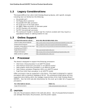
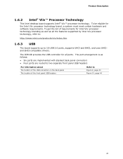
... UHCI and EHCI, and uses UHCIand EHCI-compatible drivers. Product Description 1.6.2 Intel® Viiv™ Processor Technology This Intel desktop board supports Intel® Viiv™ processor technology. To be eligible for all the features supported by Intel Viiv processor technology, refer to: http://www.intel.com/products/viiv/index.htm 1.6.3 USB The board supports up to Figure...
... UHCI and EHCI, and uses UHCIand EHCI-compatible drivers. Product Description 1.6.2 Intel® Viiv™ Processor Technology This Intel desktop board supports Intel® Viiv™ processor technology. To be eligible for all the features supported by Intel Viiv processor technology, refer to: http://www.intel.com/products/viiv/index.htm 1.6.3 USB The board supports up to Figure...
Product Specification
Page 29
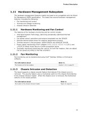
... Chassis intrusion detection 1.11.1 Hardware Monitoring and Fan Control The features of the hardware monitoring and fan control include: • Intel Quiet System Technology, delivering acoustically-optimized thermal management • Fan speed control controllers and sensors integrated into the ICH10R • ...Remote thermal diode sensor for ambient temperature sensing • Thermal sensors in the processor, 82G45 GMCH, and 82801JR ICH10R • Power supply monitoring of the fan headers Refer to Section 1.12.2.2, page 35 1.11...
... Chassis intrusion detection 1.11.1 Hardware Monitoring and Fan Control The features of the hardware monitoring and fan control include: • Intel Quiet System Technology, delivering acoustically-optimized thermal management • Fan speed control controllers and sensors integrated into the ICH10R • ...Remote thermal diode sensor for ambient temperature sensing • Thermal sensors in the processor, 82G45 GMCH, and 82801JR ICH10R • Power supply monitoring of the fan headers Refer to Section 1.12.2.2, page 35 1.11...
Product Specification
Page 30
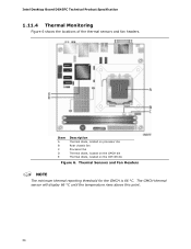
Item A B C D E Description Thermal diode, located on processor die Rear chassis fan Processor fan Thermal diode, located on the GMCH die Thermal diode, located on the ICH10R die Figure 6. Thermal Sensors and Fan Headers NOTE The minimum thermal reporting threshold for the GMCH is 66 °C. Intel Desktop Board DG45FC Technical Product Specification 1.11.4 Thermal Monitoring Figure 6 shows the locations of the thermal sensors and fan headers. The GMCH thermal sensor will display 66 °C until the temperature rises above this point. 30
Item A B C D E Description Thermal diode, located on processor die Rear chassis fan Processor fan Thermal diode, located on the GMCH die Thermal diode, located on the ICH10R die Figure 6. Thermal Sensors and Fan Headers NOTE The minimum thermal reporting threshold for the GMCH is 66 °C. Intel Desktop Board DG45FC Technical Product Specification 1.11.4 Thermal Monitoring Figure 6 shows the locations of the thermal sensors and fan headers. The GMCH thermal sensor will display 66 °C until the temperature rises above this point. 30
Product Specification
Page 32
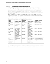
...supported by the system chassis' power supply. 2. See the ACPI specification for wake-up logic. Power States and Targeted System Power Global States Processor Sleeping States States Device States Targeted System Power (Note 1) G0 - working state. S4 - AC power is required. D3 - no ...and peripherals powered by the board along with the associated system power targets. Full power > 30 W G1 - Context not saved. Intel Desktop Board DG45FC Technical Product Specification 1.12.1.1 System States and Power States Under ACPI, the operating system directs all system and device...
...supported by the system chassis' power supply. 2. See the ACPI specification for wake-up logic. Power States and Targeted System Power Global States Processor Sleeping States States Device States Targeted System Power (Note 1) G0 - working state. S4 - AC power is required. D3 - no ...and peripherals powered by the board along with the associated system power targets. Full power > 30 W G1 - Context not saved. Intel Desktop Board DG45FC Technical Product Specification 1.12.1.1 System States and Power States Under ACPI, the operating system directs all system and device...
Product Specification
Page 35
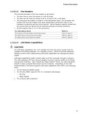
... Capabilities CAUTION For LAN wake capabilities, the +5 V standby line from the power supply must be capable of the computer through a network. The processor fan header and front fan header both have a +12 V DC connection. For information about The locations of the fan headers and thermal sensors ...The signal names of the processor fan header The signal names of the chassis fan headers Refer to the hardware monitoring and fan control device. Upon detecting a Magic Packet* ...
... Capabilities CAUTION For LAN wake capabilities, the +5 V standby line from the power supply must be capable of the computer through a network. The processor fan header and front fan header both have a +12 V DC connection. For information about The locations of the fan headers and thermal sensors ...The signal names of the processor fan header The signal names of the chassis fan headers Refer to the hardware monitoring and fan control device. Upon detecting a Magic Packet* ...
Product Specification
Page 45
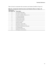
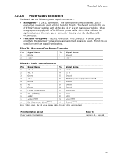
... Figure 10 Item/callout from Figure 10 Description A Front panel audio header B CIR emitter (output) header C Processor core power connector (2 X 2) D Front panel USB header E Front panel USB header F Chassis intrusion header G Front chassis fan header H Processor fan header I Serial port header J CIR receiver (input) header K Main Power connector (2 X 12) L Auxiliary front panel...
... Figure 10 Item/callout from Figure 10 Description A Front panel audio header B CIR emitter (output) header C Processor core power connector (2 X 2) D Front panel USB header E Front panel USB header F Chassis intrusion header G Front chassis fan header H Processor fan header I Serial port header J CIR receiver (input) header K Main Power connector (2 X 12) L Auxiliary front panel...
Product Specification
Page 47
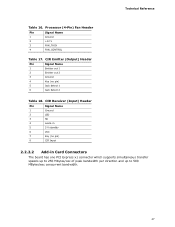
... bandwidth. 47 CIR Receiver (Input) Header Pin Signal Name 1 Ground 2 LED 3 NC 4 Learn-in 5 5 V standby 6 VCC 7 Key (no pin) 5 Jack detect 1 6 Jack detect 2 Table 18. Processor (4-Pin) Fan Header Pin Signal Name 1 Ground 2 +12 V 3 FAN_TACH 4 FAN_CONTROL Table 17. Technical Reference Table 16.
... bandwidth. 47 CIR Receiver (Input) Header Pin Signal Name 1 Ground 2 LED 3 NC 4 Learn-in 5 5 V standby 6 VCC 7 Key (no pin) 5 Jack detect 1 6 Jack detect 2 Table 18. Processor (4-Pin) Fan Header Pin Signal Name 1 Ground 2 +12 V 3 FAN_TACH 4 FAN_CONTROL Table 17. Technical Reference Table 16.
Product Specification
Page 49
..., attach that cable on the rightmost pins of the main power connector, leaving pins 11, 12, 23, and 24 unconnected. • Processor core power - Main Power Connector Pin Signal Name 1 +3.3 V 2 +3.3 V 3 Ground 4 +5 V Pin Signal Name 13 +3.3 V ...14 -12 V 15 Ground 16 PS-ON# (power supply remote on Intel Desktop boards. This connector provides power directly to the processor voltage regulator and must always be unconnected. a 2 x 2 connector. Processor Core Power Connector Pin Signal Name Pin Signal Name 1 Ground 3 +12 V 2 Ground 4 ...
..., attach that cable on the rightmost pins of the main power connector, leaving pins 11, 12, 23, and 24 unconnected. • Processor core power - Main Power Connector Pin Signal Name 1 +3.3 V 2 +3.3 V 3 Ground 4 +5 V Pin Signal Name 13 +3.3 V ...14 -12 V 15 Ground 16 PS-ON# (power supply remote on Intel Desktop boards. This connector provides power directly to the processor voltage regulator and must always be unconnected. a 2 x 2 connector. Processor Core Power Connector Pin Signal Name Pin Signal Name 1 Ground 3 +12 V 2 Ground 4 ...
Product Specification
Page 53
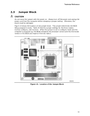
... move the jumper with the power on. When the jumper is set to configure mode and the computer is powered-up, the BIOS compares the processor version and the microcode version in the BIOS and reports if the two match.
... move the jumper with the power on. When the jumper is set to configure mode and the computer is powered-up, the BIOS compares the processor version and the microcode version in the BIOS and reports if the two match.
Product Specification
Page 56
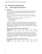
... 8 A -12 V 0.3 A 5 VSB 2.0 A For example, for a system consisting of a supported 65 W processor (see Section 1.4 on page 14 for a list of supported processors), 1 GB DDR2 RAM, one hard disk drive, one optical drive, and all onboard peripherals enabled, the minimum recommendation is... a Plus 80 150 W power supply. Table 25 lists the recommended power supply current values. Table 27 lists the recommended power supply current values. Intel...
... 8 A -12 V 0.3 A 5 VSB 2.0 A For example, for a system consisting of a supported 65 W processor (see Section 1.4 on page 14 for a list of supported processors), 1 GB DDR2 RAM, one hard disk drive, one optical drive, and all onboard peripherals enabled, the minimum recommendation is... a Plus 80 150 W power supply. Table 25 lists the recommended power supply current values. Table 27 lists the recommended power supply current values. Intel...
Product Specification
Page 57
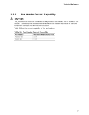
Fan Header Current Capability Fan Header Maximum Available Current Processor fan Chassis fan 2.0 A 1.5 A 57 Technical Reference 2.5.2 Fan Header Current Capability CAUTION The processor fan must be connected to the processor fan header, not to a chassis fan header may result in onboard component damage that will halt fan operation. Table 28 lists the current capability of the fan headers. Table 28. Connecting the processor fan to a chassis fan header.
Fan Header Current Capability Fan Header Maximum Available Current Processor fan Chassis fan 2.0 A 1.5 A 57 Technical Reference 2.5.2 Fan Header Current Capability CAUTION The processor fan must be connected to the processor fan header, not to a chassis fan header may result in onboard component damage that will halt fan operation. Table 28 lists the current capability of the fan headers. Table 28. Connecting the processor fan to a chassis fan header.
Product Specification
Page 58
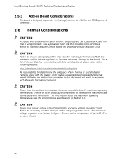
...cooling.htm All responsibility for the PCI Express x1 connector. 2.6 Thermal Considerations CAUTION A chassis with Intel desktop boards please refer to maintain required airflow across the processor voltage regulator area. For information about the maximum operating temperature, see the environmental specifications in a ...the reader. Failure to do so could cause components to exceed their maximum case temperature and malfunction. For a list of both the processor and/or voltage regulator or, in Board Considerations The board is designed to provide 2 A (average) current at +5 V for ...
...cooling.htm All responsibility for the PCI Express x1 connector. 2.6 Thermal Considerations CAUTION A chassis with Intel desktop boards please refer to maintain required airflow across the processor voltage regulator area. For information about the maximum operating temperature, see the environmental specifications in a ...the reader. Failure to do so could cause components to exceed their maximum case temperature and malfunction. For a list of both the processor and/or voltage regulator or, in Board Considerations The board is designed to provide 2 A (average) current at +5 V for ...
Product Specification
Page 59
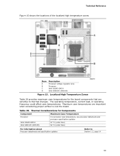
... temperatures for Components Component Maximum Case Temperature Processor For processor case temperature, see processor datasheets and processor specification updates Intel 82G45 GMCH Intel 82801JR (ICH10R) 97 oC (under bias) 92 oC (under bias) For information about Processor datasheets and specification updates Refer to cool the board. Item A B C D Description Processor voltage regulator area Processor Intel 82G45 GMCH Intel 82801JR (ICH10R) Figure 15.
... temperatures for Components Component Maximum Case Temperature Processor For processor case temperature, see processor datasheets and processor specification updates Intel 82G45 GMCH Intel 82801JR (ICH10R) 97 oC (under bias) 92 oC (under bias) For information about Processor datasheets and specification updates Refer to cool the board. Item A B C D Description Processor voltage regulator area Processor Intel 82G45 GMCH Intel 82801JR (ICH10R) Figure 15.

Product Specification
Page 62
BIOS Setup Program Menu Bar Maintenance Main Advanced Security Clears passwords and displays processor information Displays processor and memory configuration Configures advanced features available through the chipset Sets passwords and security features Power Boot ... automatically configures interrupts, the I/O space, and other system resources. PCI devices may be available for use by the add-in cards. Intel Desktop Board DG45FC Technical Product Specification Table 31 lists the BIOS Setup program menu features. Autoconfiguration lets a user insert or remove PCI cards...
BIOS Setup Program Menu Bar Maintenance Main Advanced Security Clears passwords and displays processor information Displays processor and memory configuration Configures advanced features available through the chipset Sets passwords and security features Power Boot ... automatically configures interrupts, the I/O space, and other system resources. PCI devices may be available for use by the add-in cards. Intel Desktop Board DG45FC Technical Product Specification Table 31 lists the BIOS Setup program menu features. Autoconfiguration lets a user insert or remove PCI cards...
Product Specification
Page 63
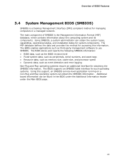
... BIOS revision level • Fixed-system data, such as peripherals, serial numbers, and asset tags • Resource data, such as memory size, cache size, and processor speed • Dynamic data, such as third-party management software to use SMBIOS. Overview of SMBIOS is a Desktop Management Interface (DMI) compliant method for managing...
... BIOS revision level • Fixed-system data, such as peripherals, serial numbers, and asset tags • Resource data, such as memory size, cache size, and processor speed • Dynamic data, such as third-party management software to use SMBIOS. Overview of SMBIOS is a Desktop Management Interface (DMI) compliant method for managing...
Product Specification
Page 72
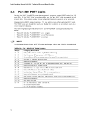
...console codes). AF Reserved for future use . 50 - 5F 60 - 6F I /O port 80h. B0 - EE: Miscellaneous codes. FF: FF processor exception. 72 FF E0 - CF D0 - F0 - Displaying the POST codes requires a PCI bus add-in hexadecimal. Reserved for future use (...7F Output Devices: All output consoles. 7F is an unrecoverable error. 80 - 8F Reserved for future use . Boot device selection. C0 - Intel Desktop Board DG45FC Technical Product Specification 4.4 Port 80h POST Codes During the POST, the BIOS generates diagnostic progress codes (POST codes) to I ...
...console codes). AF Reserved for future use . 50 - 5F 60 - 6F I /O port 80h. B0 - EE: Miscellaneous codes. FF: FF processor exception. 72 FF E0 - CF D0 - F0 - Displaying the POST codes requires a PCI bus add-in hexadecimal. Reserved for future use (...7F Output Devices: All output consoles. 7F is an unrecoverable error. 80 - 8F Reserved for future use . Boot device selection. C0 - Intel Desktop Board DG45FC Technical Product Specification 4.4 Port 80h POST Codes During the POST, the BIOS generates diagnostic progress codes (POST codes) to I ...


