
Product Specification
Page 6
... Features 3.1 Introduction 61 3.2 System Management BIOS (SMBIOS 63 3.3 Legacy USB Support 63 3.4 BIOS Updates 64 3.4.1 Language Support 64 3.4.2 Custom Splash Screen 65 3.5 BIOS Recovery 65 3.6 Boot Options 66 3.6.1 Optical Drive Boot 66 3.6.2 Network Boot 66 3.6.3 Booting Without Attached Devices 66 3.6.4 Changing the Default Boot Device During POST 66 3.7 BIOS Security Features 67 4 Error Messages and Beep Codes 4.1 Speaker 69 4.2 BIOS Beep Codes 69 4.3 Front-panel Power LED Blink Codes 70 4.4 BIOS Error Messages 70 4.5 Port 80h POST Codes 71 5 Regulatory Compliance and...
... Features 3.1 Introduction 61 3.2 System Management BIOS (SMBIOS 63 3.3 Legacy USB Support 63 3.4 BIOS Updates 64 3.4.1 Language Support 64 3.4.2 Custom Splash Screen 65 3.5 BIOS Recovery 65 3.6 Boot Options 66 3.6.1 Optical Drive Boot 66 3.6.2 Network Boot 66 3.6.3 Booting Without Attached Devices 66 3.6.4 Changing the Default Boot Device During POST 66 3.7 BIOS Security Features 67 4 Error Messages and Beep Codes 4.1 Speaker 69 4.2 BIOS Beep Codes 69 4.3 Front-panel Power LED Blink Codes 70 4.4 BIOS Error Messages 70 4.5 Port 80h POST Codes 71 5 Regulatory Compliance and...

Product Specification
Page 7
.... Back Panel Connectors 40 10. Serial Port Header 43 14. Front Panel USB Headers 44 19. Detailed System Memory Address Map 38 9. Major Board Components 11 2. Supported Memory Configurations 15 4. Contents Figures 1. Component-side Connectors and Headers Shown in Figure 1 12 3. S/PDIF Header 43 15. Front and Rear Chassis Fan Headers 45 23. Processor Core Power Connector 46 27. Board Dimensions 53 16. Block Diagram 13 3. Wake-up Devices and Events 30 11. Audio Jack Retasking Support 21 7. LAN Connector LED Locations 24...
.... Back Panel Connectors 40 10. Serial Port Header 43 14. Front Panel USB Headers 44 19. Detailed System Memory Address Map 38 9. Major Board Components 11 2. Supported Memory Configurations 15 4. Contents Figures 1. Component-side Connectors and Headers Shown in Figure 1 12 3. S/PDIF Header 43 15. Front and Rear Chassis Fan Headers 45 23. Processor Core Power Connector 46 27. Board Dimensions 53 16. Block Diagram 13 3. Wake-up Devices and Events 30 11. Audio Jack Retasking Support 21 7. LAN Connector LED Locations 24...

Product Specification
Page 8
Alternate Front Panel Power LED Header 49 31. Acceptable Drives/Media Types for Components 58 36. Boot Device Menu Options 66 41. Product Certification Markings 84 14H 319H viii Fan Header Current Capability 55 34. BIOS Beep Codes 69 43. Port 80h POST Codes 72 47. Tcontrol Values for BIOS Recovery 65 40. BIOS Setup Program Function Keys 62 39. Lead-Free Board Markings 82 50. Environmental Specifications 59 37. BIOS Error Messages 70 45. Typical Port 80h POST Sequence 75...
Alternate Front Panel Power LED Header 49 31. Acceptable Drives/Media Types for Components 58 36. Boot Device Menu Options 66 41. Product Certification Markings 84 14H 319H viii Fan Header Current Capability 55 34. BIOS Beep Codes 69 43. Port 80h POST Codes 72 47. Tcontrol Values for BIOS Recovery 65 40. BIOS Setup Program Function Keys 62 39. Lead-Free Board Markings 82 50. Environmental Specifications 59 37. BIOS Error Messages 70 45. Typical Port 80h POST Sequence 75...

Product Specification
Page 9
... SPI Flash device • Support for up to 16 GB of the board. Table 1. 1 Product Description 1.1 Overview 1.1.1 Feature Summary Table 1 summarizes the major features of system memory with four DIMMs using 2 Gb memory technology • Support for non-ECC memory • Integrated graphics support for processors with Intel HD Graphics: ― High Definition Multimedia Interface* (HDMI*) ― DVI-I /O controller for serial port support • Intel® BIOS resident in graphics card • 10-channel (7.1+2) Intel® High Definition Audio...
... SPI Flash device • Support for up to 16 GB of the board. Table 1. 1 Product Description 1.1 Overview 1.1.1 Feature Summary Table 1 summarizes the major features of system memory with four DIMMs using 2 Gb memory technology • Support for non-ECC memory • Integrated graphics support for processors with Intel HD Graphics: ― High Definition Multimedia Interface* (HDMI*) ― DVI-I /O controller for serial port support • Intel® BIOS resident in graphics card • 10-channel (7.1+2) Intel® High Definition Audio...

Product Specification
Page 12
... R Chassis intrusion header S Main power connector (2 x 12) T Piezoelectric speaker U SATA connectors V Intel Remote Assist PC header W Alternate front panel power LED header X Front panel header Y Front panel USB header Z Standby power LED AA Front panel USB header BB Front panel USB header CC Front panel USB header DD BIOS setup configuration jumper block EE Intel H57 Express Chipset FF Intel High Definition Audio Link header GG Serial port header HH S/PDIF header II Front panel audio header 12 Intel Desktop Board DH57DD Technical Product Specification...
... R Chassis intrusion header S Main power connector (2 x 12) T Piezoelectric speaker U SATA connectors V Intel Remote Assist PC header W Alternate front panel power LED header X Front panel header Y Front panel USB header Z Standby power LED AA Front panel USB header BB Front panel USB header CC Front panel USB header DD BIOS setup configuration jumper block EE Intel H57 Express Chipset FF Intel High Definition Audio Link header GG Serial port header HH S/PDIF header II Front panel audio header 12 Intel Desktop Board DH57DD Technical Product Specification...

Product Specification
Page 14
...intel.com CAUTION Use only the processors listed on power supply requirements for the Intel Desktop Board DH57DD Supported processors Chipset information BIOS and driver updates Tested memory Integration information Visit this board. 14 Intel Desktop Board DH57DD Technical Product Specification 1.2 Legacy Considerations This board differs from other Intel Desktop Board products, with a maximum TDP of 87 W. See the Intel web site listed below for providing power to support the Intel Core i7, Intel Core i5, Intel Core i3, Intel Pentium processors, and Intel Xeon processor 3400 series...
...intel.com CAUTION Use only the processors listed on power supply requirements for the Intel Desktop Board DH57DD Supported processors Chipset information BIOS and driver updates Tested memory Integration information Visit this board. 14 Intel Desktop Board DH57DD Technical Product Specification 1.2 Legacy Considerations This board differs from other Intel Desktop Board products, with a maximum TDP of 87 W. See the Intel web site listed below for providing power to support the Intel Core i7, Intel Core i5, Intel Core i3, Intel Pentium processors, and Intel Xeon processor 3400 series...

Product Specification
Page 15
...) and "SS" refers to the processor and the USB, SATA, LPC, audio, network, display, Conventional PCI, and PCI Express x1 interfaces. Product Description 1.5 Intel® H57 Express Chipset The Intel H57 Express Chipset consisting of the Intel H57 Platform Controller Hub (PCH) provides interfaces to single-sided memory modules (containing one row of addressable memory. • Minimum total system memory: 512MB using 1 Gb x16 module • Serial Presence Detect • DDR3 1333...
...) and "SS" refers to the processor and the USB, SATA, LPC, audio, network, display, Conventional PCI, and PCI Express x1 interfaces. Product Description 1.5 Intel® H57 Express Chipset The Intel H57 Express Chipset consisting of the Intel H57 Platform Controller Hub (PCH) provides interfaces to single-sided memory modules (containing one row of addressable memory. • Minimum total system memory: 512MB using 1 Gb x16 module • Serial Presence Detect • DDR3 1333...

Product Specification
Page 18
...memory configuration 1.7.1.2 High Definition Multimedia Interface* (HDMI*) The HDMI port supports standard, enhanced, or high definition video, plus multichannel digital audio on the type of add-in card installed in the PCI Express x16 connector, the HDMI port will behave as Dolby* TrueHD or DTS* HD Master Audio. Intel Desktop Board DH57DD Technical Product Specification 1.7 Graphics Subsystem The board supports system graphics through either Intel HD Graphics or a PCI Express 2.0 x16 add-in graphics card. 1.7.1 Integrated Graphics The board supports integrated graphics through the Intel...
...memory configuration 1.7.1.2 High Definition Multimedia Interface* (HDMI*) The HDMI port supports standard, enhanced, or high definition video, plus multichannel digital audio on the type of add-in card installed in the PCI Express x16 connector, the HDMI port will behave as Dolby* TrueHD or DTS* HD Master Audio. Intel Desktop Board DH57DD Technical Product Specification 1.7 Graphics Subsystem The board supports system graphics through either Intel HD Graphics or a PCI Express 2.0 x16 add-in graphics card. 1.7.1 Integrated Graphics The board supports integrated graphics through the Intel...

Product Specification
Page 19
... be converted to VGA using a DVI-VGA converter. The DVI port is 4 GB/s in each direction, simultaneously, when operating in x16 mode. 1.8 USB The board supports up to VGA with four dual-port internal headers 19 DVI Port Status Conditions PCI Express x16 Connector Status No add-in card installed Non-video PCI Express x1 add-in card installed PCI Express x16 add-in card installed DVI Digital (DVI-D) Port Status Enabled Enabled DVI Analog (DVI-A) Port Status(Note) Enabled Enabled Disabled Disabled Note: DVI analog...
... be converted to VGA using a DVI-VGA converter. The DVI port is 4 GB/s in each direction, simultaneously, when operating in x16 mode. 1.8 USB The board supports up to VGA with four dual-port internal headers 19 DVI Port Status Conditions PCI Express x16 Connector Status No add-in card installed Non-video PCI Express x1 add-in card installed PCI Express x16 add-in card installed DVI Digital (DVI-D) Port Status Enabled Enabled DVI Analog (DVI-A) Port Status(Note) Enabled Enabled Disabled Disabled Note: DVI analog...

Product Specification
Page 28
...; Software support through Advanced Configuration and Power Interface (ACPI) • Hardware support: ⎯ Power connector ⎯ Fan headers ⎯ LAN wake capabilities ⎯ Instantly Available PC technology ⎯ Wake from USB ⎯ PCI Express WAKE# signal support ⎯ Wake from serial port ⎯ Wake from Consumer IR 1.15.1 ACPI ACPI gives the operating system direct control over the power management and Plug and Play functions of individual devices, add-in boards (some add-in boards may require an ACPI-aware driver), video displays, and hard disk drives •...
...; Software support through Advanced Configuration and Power Interface (ACPI) • Hardware support: ⎯ Power connector ⎯ Fan headers ⎯ LAN wake capabilities ⎯ Instantly Available PC technology ⎯ Wake from USB ⎯ PCI Express WAKE# signal support ⎯ Wake from serial port ⎯ Wake from Consumer IR 1.15.1 ACPI ACPI gives the operating system direct control over the power management and Plug and Play functions of individual devices, add-in boards (some add-in boards may require an ACPI-aware driver), video displays, and hard disk drives •...

Product Specification
Page 50
... power on the USB headers is fused. • Use only a front panel USB connector that conforms to the USB 2.0 specification for IEEE 1394a Header 50 Connection Diagram for high-speed USB devices. NOTE • The +5 V DC power on the IEEE 1394a header is fused. • The IEEE 1394a header provides one IEEE 1394a port. Intel Desktop Board DH57DD Technical Product Specification 2.2.2.6 Front Panel USB Headers Figure 12 is a connection diagram for the IEEE 1394a header. Connection Diagram for Front Panel USB Headers 2.2.2.7 Front Panel IEEE 1394a Header...
... power on the USB headers is fused. • Use only a front panel USB connector that conforms to the USB 2.0 specification for IEEE 1394a Header 50 Connection Diagram for high-speed USB devices. NOTE • The +5 V DC power on the IEEE 1394a header is fused. • The IEEE 1394a header provides one IEEE 1394a port. Intel Desktop Board DH57DD Technical Product Specification 2.2.2.6 Front Panel USB Headers Figure 12 is a connection diagram for the IEEE 1394a header. Connection Diagram for Front Panel USB Headers 2.2.2.7 Front Panel IEEE 1394a Header...

Product Specification
Page 61
... put the board in Maintenance mode. 3 Overview of BIOS Features 3.1 Introduction The board uses an Intel BIOS that is accessed by pressing the key after the Power-On Self-Test (POST) memory test begins and before the operating system boot begins. The SPI Flash contains the BIOS Setup program, POST, LAN EEPROM information, Plug and Play support, and other firmware. Maintenance Main Advanced Performance Security Power Boot Exit NOTE The maintenance menu is displayed only when...
... put the board in Maintenance mode. 3 Overview of BIOS Features 3.1 Introduction The board uses an Intel BIOS that is accessed by pressing the key after the Power-On Self-Test (POST) memory test begins and before the operating system boot begins. The SPI Flash contains the BIOS Setup program, POST, LAN EEPROM information, Plug and Play support, and other firmware. Maintenance Main Advanced Performance Security Power Boot Exit NOTE The maintenance menu is displayed only when...

Product Specification
Page 63
... period if Legacy USB support was set to enter and configure the BIOS Setup program and the maintenance menu. 4. Legacy USB support is loading, USB keyboards and mice are recognized and may be used to access the BIOS Setup program, and to Disabled in the BIOS Setup program.) 6. POST begins. 3. POST completes. 5. While the operating system is used even when the operating system's USB drivers are not yet available. Overview of SMBIOS is disabled. 2. By default, Legacy USB support is enabled by the...
... period if Legacy USB support was set to enter and configure the BIOS Setup program and the maintenance menu. 4. Legacy USB support is loading, USB keyboards and mice are recognized and may be used to access the BIOS Setup program, and to Disabled in the BIOS Setup program.) 6. POST begins. 3. POST completes. 5. While the operating system is used even when the operating system's USB drivers are not yet available. Overview of SMBIOS is disabled. 2. By default, Legacy USB support is enabled by the...
Product Specification
Page 66
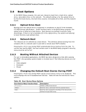
... the onboard LAN or a network add-in compliance to boot from the LAN. Boot devices are not present: • Video adapter • Keyboard • Mouse 3.6.4 Changing the Default Boot Device During POST Pressing the key during POST causes a boot device menu to be displayed. The default setting is for the optical drive to the boot priority defined through BIOS setup 66 This menu displays the list of available boot devices. Intel Desktop Board DH57DD Technical Product Specification 3.6 Boot Options In the BIOS Setup program, the user can be selected as a boot device...
... the onboard LAN or a network add-in compliance to boot from the LAN. Boot devices are not present: • Video adapter • Keyboard • Mouse 3.6.4 Changing the Default Boot Device During POST Pressing the key during POST causes a boot device menu to be displayed. The default setting is for the optical drive to the boot priority defined through BIOS setup 66 This menu displays the list of available boot devices. Intel Desktop Board DH57DD Technical Product Specification 3.6 Boot Options In the BIOS Setup program, the user can be selected as a boot device...

Product Specification
Page 67
... setting the supervisor password and user password. Password to Enter Setup None Password During Boot None Supervisor None User User Supervisor or Supervisor or user user 67 The password prompt will be displayed before the computer is set, pressing the key at the password prompt of the BIOS Setup program allows the user restricted access to Setup. • If both passwords are A-Z, a-z, and 0-9. Supervisor and User Password Functions Password Set Supervisor Mode User Mode Setup Options Neither Can change all Can change all None options (Note) options...
... setting the supervisor password and user password. Password to Enter Setup None Password During Boot None Supervisor None User User Supervisor or Supervisor or user user 67 The password prompt will be displayed before the computer is set, pressing the key at the password prompt of the BIOS Setup program allows the user restricted access to Setup. • If both passwords are A-Z, a-z, and 0-9. Supervisor and User Password Functions Password Set Supervisor Mode User Mode Setup Options Neither Can change all Can change all None options (Note) options...

Product Specification
Page 70
.... Replace the battery soon. CMOS memory may be losing power. Table 44. Run Setup to boot. 70 Front-panel Power LED Blink Codes Type Pattern F2 Setup/F10 Boot Menu None Prompt BIOS update in graphics card installed) Memory error On-off for 0.5 seconds, then off (0.5 second each . Thermal trip warning Each beep will result in graphics card 4.4 BIOS Error Messages Table 44 lists the error messages and provides a brief description of 32 blinks. Intel Desktop Board DH57DD Technical Product Specification 4.3 Front-panel Power LED Blink Codes...
.... Replace the battery soon. CMOS memory may be losing power. Table 44. Run Setup to boot. 70 Front-panel Power LED Blink Codes Type Pattern F2 Setup/F10 Boot Menu None Prompt BIOS update in graphics card installed) Memory error On-off for 0.5 seconds, then off (0.5 second each . Thermal trip warning Each beep will result in graphics card 4.4 BIOS Error Messages Table 44 lists the error messages and provides a brief description of 32 blinks. Intel Desktop Board DH57DD Technical Product Specification 4.3 Front-panel Power LED Blink Codes...
Product Specification
Page 71
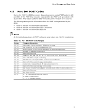
... failure. If the POST fails, execution stops and the last POST code generated is an unrecoverable error. FF E0 - AF B0 - Reserved for future use (new output console codes). 90 - 9F Input devices: Keyboard/Mouse. 9F is no memory detected or no useful memory detected. 30 - 3F 40 - 4F Recovery: 3F indicated recovery failure. Error Messages and Beep Codes 4.5 Port 80h POST Codes During the POST, the BIOS generates diagnostic progress codes (POST codes) to I /O Busses: PCI, USB...
... failure. If the POST fails, execution stops and the last POST code generated is an unrecoverable error. FF E0 - AF B0 - Reserved for future use (new output console codes). 90 - 9F Input devices: Keyboard/Mouse. 9F is no memory detected or no useful memory detected. 30 - 3F 40 - 4F Recovery: 3F indicated recovery failure. Error Messages and Beep Codes 4.5 Port 80h POST Codes During the POST, the BIOS generates diagnostic progress codes (POST codes) to I /O Busses: PCI, USB...

Product Specification
Page 73
... Resetting removable media B9 Disabling removable media BA Detecting presence of a removable media (CD-ROM detection, etc.) BC Enabling/configuring a removable media BDS Dy Trying boot selection y (y=0 to 15) PEI Core E0 Started dispatching PEIMs (emitted on first report of EFI_SW_PC_INIT_BEGIN EFI_SW_PEI_PC_HANDOFF_TO_NEXT) E2 E1, E3 Permanent memory found Reserved for PEI/PEIMs DXE Core E4 Entered DXE phase E5 Started dispatching drivers E6 Started connecting drivers continued 73 Error Messages and Beep Codes...
... Resetting removable media B9 Disabling removable media BA Detecting presence of a removable media (CD-ROM detection, etc.) BC Enabling/configuring a removable media BDS Dy Trying boot selection y (y=0 to 15) PEI Core E0 Started dispatching PEIMs (emitted on first report of EFI_SW_PC_INIT_BEGIN EFI_SW_PEI_PC_HANDOFF_TO_NEXT) E2 E1, E3 Permanent memory found Reserved for PEI/PEIMs DXE Core E4 Entered DXE phase E5 Started dispatching drivers E6 Started connecting drivers continued 73 Error Messages and Beep Codes...

Product Specification
Page 74
Intel Desktop Board DH57DD Technical Product Specification Table 46. Port 80h POST Codes (continued) POST Code Description of POST Operation DXE Drivers E7 Waiting for user input E8 Checking password E9 Entering BIOS setup EB Calling Legacy Option ROMs Runtime Phase/EFI OS Boot F4 Entering Sleep state F5 Exiting Sleep state F8 EFI boot service ExitBootServices ( ) has been called F9 EFI runtime service SetVirtualAddressMap ( ) has been called FA EFI runtime service ResetSystem ( ) has been called PEIMs/Recovery 30...
Intel Desktop Board DH57DD Technical Product Specification Table 46. Port 80h POST Codes (continued) POST Code Description of POST Operation DXE Drivers E7 Waiting for user input E8 Checking password E9 Entering BIOS setup EB Calling Legacy Option ROMs Runtime Phase/EFI OS Boot F4 Entering Sleep state F5 Exiting Sleep state F8 EFI boot service ExitBootServices ( ) has been called F9 EFI runtime service SetVirtualAddressMap ( ) has been called FA EFI runtime service ResetSystem ( ) has been called PEIMs/Recovery 30...

Product Specification
Page 75
... POST Code Description 21 Initializing a chipset component 22 Reading SPD from memory DIMMs 23 Detecting presence of memory DIMMs 25 Configuring memory 28 Testing memory 34 Loading recovery capsule E4 Entered DXE phase 12 Starting application processor initialization 13 SMM initialization 50 Enumerating PCI busses 51 Allocating resourced to PCI bus 92 Detecting the presence of the keyboard 90 Resetting keyboard 94 Clearing keyboard input buffer 95 Keyboard Self Test EB Calling Video BIOS...
... POST Code Description 21 Initializing a chipset component 22 Reading SPD from memory DIMMs 23 Detecting presence of memory DIMMs 25 Configuring memory 28 Testing memory 34 Loading recovery capsule E4 Entered DXE phase 12 Starting application processor initialization 13 SMM initialization 50 Enumerating PCI busses 51 Allocating resourced to PCI bus 92 Detecting the presence of the keyboard 90 Resetting keyboard 94 Clearing keyboard input buffer 95 Keyboard Self Test EB Calling Video BIOS...


