
Product Specification
Page 7
... Shown in Figure 10 42 13. Audio Jack Retasking Support 21 7. Wake-up Devices and Events 30 11. Location of the Jumper Block 51 15. Intel HD Audio Link Header 44 18. Effects of Pressing the Power Switch 28 9. Component-side Connectors and Headers 41 11. Connection Diagram for Front Panel... States and Targeted System Power 29 10. System Memory Map 39 12. Chassis Intrusion Header 44 21. Front Panel CIR Receiver (Input) Header 45 26. Main Power Connector 47 vii
... Shown in Figure 10 42 13. Audio Jack Retasking Support 21 7. Wake-up Devices and Events 30 11. Location of the Jumper Block 51 15. Intel HD Audio Link Header 44 18. Effects of Pressing the Power Switch 28 9. Component-side Connectors and Headers 41 11. Connection Diagram for Front Panel... States and Targeted System Power 29 10. System Memory Map 39 12. Chassis Intrusion Header 44 21. Front Panel CIR Receiver (Input) Header 45 26. Main Power Connector 47 vii

Product Specification
Page 12
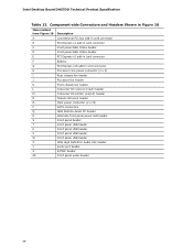
... Front chassis fan header P Consumer IR receiver (input) header Q Consumer IR emitter (output) header R Chassis intrusion header S Main power connector (2 x 12) T Piezoelectric speaker U SATA connectors V Intel Remote Assist PC header W Alternate front panel power LED header X Front panel header Y Front panel USB header Z Standby power...panel USB header CC Front panel USB header DD BIOS setup configuration jumper block EE Intel H57 Express Chipset FF Intel High Definition Audio Link header GG Serial port header HH S/PDIF header II Front panel audio header 12...
... Front chassis fan header P Consumer IR receiver (input) header Q Consumer IR emitter (output) header R Chassis intrusion header S Main power connector (2 x 12) T Piezoelectric speaker U SATA connectors V Intel Remote Assist PC header W Alternate front panel power LED header X Front panel header Y Front panel USB header Z Standby power...panel USB header CC Front panel USB header DD BIOS setup configuration jumper block EE Intel H57 Express Chipset FF Intel High Definition Audio Link header GG Serial port header HH S/PDIF header II Front panel audio header 12...

Product Specification
Page 31
...off ). When an ACPI-enabled system receives the correct command, the power supply removes all non-standby voltages. The total amount of the main power connector Refer to Figure 10, page 41 Table 27, page 47 31 The board provides several power management hardware features, including: •... the wake devices supported and manufacturing options. The computer's response can damage the power supply. For information about The location of the main power connector The signal names of standby current required depends on or off the system power through system control. NOTE The use of ...
...off ). When an ACPI-enabled system receives the correct command, the power supply removes all non-standby voltages. The total amount of the main power connector Refer to Figure 10, page 41 Table 27, page 47 31 The board provides several power management hardware features, including: •... the wake devices supported and manufacturing options. The computer's response can damage the power supply. For information about The location of the main power connector The signal names of standby current required depends on or off the system power through system control. NOTE The use of ...
Product Specification
Page 42
...fan header Front chassis fan header Consumer IR receiver (input) header Consumer IR emitter (output) header Chassis intrusion header Main power connector (2 x 12) SATA connectors Intel Remote Assist PC header Alternate front panel power LED header Front panel header Front panel USB header Front panel USB header... Front panel USB header Front panel USB header Intel High Definition Audio Link header Serial port header S/PDIF header Front panel audio header 42 Intel Desktop Board DH57DD Technical Product Specification Table 12.
...fan header Front chassis fan header Consumer IR receiver (input) header Consumer IR emitter (output) header Chassis intrusion header Main power connector (2 x 12) SATA connectors Intel Remote Assist PC header Alternate front panel power LED header Front panel header Front panel USB header Front panel USB header... Front panel USB header Front panel USB header Intel High Definition Audio Link header Serial port header S/PDIF header Front panel audio header 42 Intel Desktop Board DH57DD Technical Product Specification Table 12.
Product Specification
Page 46
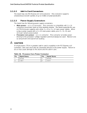
...(75 W or greater) add-in the PCI Express x16 connector, that card must remain unconnected. • Processor core power - Table 26. Intel Desktop Board DH57DD Technical Product Specification 2.2.2.2 Add-in card. This connector is installed in card is compatible with 2 x 10 connectors previously used ...one PCI Express 2.0 x16 connector. Failure to 8 GB/s of ATX12V power supplies with a 2 x 10 main power cable, pins 11, 12, 23, and 24 must also be used on Intel Desktop boards. a 2 x 12 connector. Processor Core Power Connector Pin Signal Name Pin Signal Name 1 Ground...
...(75 W or greater) add-in the PCI Express x16 connector, that card must remain unconnected. • Processor core power - Table 26. Intel Desktop Board DH57DD Technical Product Specification 2.2.2.2 Add-in card. This connector is installed in card is compatible with 2 x 10 connectors previously used ...one PCI Express 2.0 x16 connector. Failure to 8 GB/s of ATX12V power supplies with a 2 x 10 main power cable, pins 11, 12, 23, and 24 must also be used on Intel Desktop boards. a 2 x 12 connector. Processor Core Power Connector Pin Signal Name Pin Signal Name 1 Ground...

Product Specification
Page 47
... Refer to Section 2.5.1 on /off) Ground Ground Ground −5 V (obsolete) +5 V +5 V +5 V (Note) Ground (Note) Note: When using a 2 x 10 power supply cable, this pin will be unconnected. Main Power Connector Pin Signal Name Pin 1 +3.3 V 13 2 +3.3 V 14 3 Ground 15 4 +5 V 16 5 Ground 17 6 +5 V 18 7 Ground 19 8 PWRGD (Power Good) 20 9 +5 V (Standby) 21 10 +12 V 22...
... Refer to Section 2.5.1 on /off) Ground Ground Ground −5 V (obsolete) +5 V +5 V +5 V (Note) Ground (Note) Note: When using a 2 x 10 power supply cable, this pin will be unconnected. Main Power Connector Pin Signal Name Pin 1 +3.3 V 13 2 +3.3 V 14 3 Ground 15 4 +5 V 16 5 Ground 17 6 +5 V 18 7 Ground 19 8 PWRGD (Power Good) 20 9 +5 V (Standby) 21 10 +12 V 22...

Product Specification
Page 61
...BIOSs are identified as JGIBX10J.86A. Section 2.3 on page 51 shows how to view and change the BIOS settings for the computer. Maintenance Main Advanced Performance Security Power Boot Exit NOTE The maintenance menu is displayed only when the board is in Maintenance mode. 61 The BIOS Setup ...program can be used to put the board in Maintenance mode. 3 Overview of BIOS Features 3.1 Introduction The board uses an Intel BIOS that is stored in a 64 Mbit (8,192 KB) Serial Peripheral Interface Flash Memory (SPI Flash) device which can be updated using a set ...
...BIOSs are identified as JGIBX10J.86A. Section 2.3 on page 51 shows how to view and change the BIOS settings for the computer. Maintenance Main Advanced Performance Security Power Boot Exit NOTE The maintenance menu is displayed only when the board is in Maintenance mode. 61 The BIOS Setup ...program can be used to put the board in Maintenance mode. 3 Overview of BIOS Features 3.1 Introduction The board uses an Intel BIOS that is stored in a 64 Mbit (8,192 KB) Serial Peripheral Interface Flash Memory (SPI Flash) device which can be updated using a set ...

Product Specification
Page 62
BIOS Setup Program Menu Bar Maintenance Main Advanced Performance Security Clears passwords and displays processor information Displays processor and memory configuration Configures advanced features available through the chipset Configures Memory and Processor ... cursor up or down) Selects sub-items within a field (i.e., date/time) Executes command or selects the submenu Load the default configuration values for menu screens. Intel Desktop Board DH57DD Technical Product Specification Table 37 lists the BIOS Setup program menu features. Table 37.
BIOS Setup Program Menu Bar Maintenance Main Advanced Performance Security Clears passwords and displays processor information Displays processor and memory configuration Configures advanced features available through the chipset Configures Memory and Processor ... cursor up or down) Selects sub-items within a field (i.e., date/time) Executes command or selects the submenu Load the default configuration values for menu screens. Intel Desktop Board DH57DD Technical Product Specification Table 37 lists the BIOS Setup program menu features. Table 37.

Product Specification
Page 63
...BIOS Setup program and the maintenance menu. 4. Additional board information can be found in the BIOS under the Additional Information header under the Main BIOS page. 3.3 Legacy USB Support Legacy USB support enables USB devices to be used to access the BIOS Setup program, and to ...USB drivers, all legacy and non-legacy USB devices are recognized by the BIOS allowing you apply power to Disabled in a managed network. The main component of BIOS Features 3.2 System Management BIOS (SMBIOS) SMBIOS is a Desktop Management Interface (DMI) compliant method for system components. The BIOS ...
...BIOS Setup program and the maintenance menu. 4. Additional board information can be found in the BIOS under the Additional Information header under the Main BIOS page. 3.3 Legacy USB Support Legacy USB support enables USB devices to be used to access the BIOS Setup program, and to ...USB drivers, all legacy and non-legacy USB devices are recognized by the BIOS allowing you apply power to Disabled in a managed network. The main component of BIOS Features 3.2 System Management BIOS (SMBIOS) SMBIOS is a Desktop Management Interface (DMI) compliant method for system components. The BIOS ...