Product Specification
Page 3
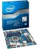
... for Intel® Desktop Board DH67VR. Preface This Technical Product Specification (TPS) specifies the board layout, components, connectors, power and environmental requirements, and the BIOS for general audiences. What This Document Contains Chapter 1 2 3 4 5 Description A description of the hardware used in all specifications of this level of the BIOS error messages, beep codes, and POST codes Regulatory compliance and battery disposal information Typographical Conventions This section contains information about Intel Desktop Board...
... for Intel® Desktop Board DH67VR. Preface This Technical Product Specification (TPS) specifies the board layout, components, connectors, power and environmental requirements, and the BIOS for general audiences. What This Document Contains Chapter 1 2 3 4 5 Description A description of the hardware used in all specifications of this level of the BIOS error messages, beep codes, and POST codes Regulatory compliance and battery disposal information Typographical Conventions This section contains information about Intel Desktop Board...

Product Specification
Page 6
...3.5 Legacy USB Support 61 3.6 BIOS Updates 62 3.6.1 Language Support 62 3.6.2 Custom Splash Screen 63 3.7 BIOS Recovery 63 3.8 Boot Options 64 3.8.1 Optical Drive Boot 64 3.8.2 Network Boot 64 3.8.3 Booting Without Attached Devices 64 3.8.4 Changing the Default Boot Device During POST 64 3.9 Adjusting Boot Speed 65 3.9.1 Peripheral Selection and Configuration 65 3.9.2 BIOS Boot Optimizations 65 3.10 BIOS Security Features 66 3.11 BIOS Performance Features 67 4 Error Messages and Beep Codes 4.1 Speaker 69 4.2 BIOS Beep Codes 69 4.3 Front-panel Power LED Blink Codes 70 4.4 BIOS...
...3.5 Legacy USB Support 61 3.6 BIOS Updates 62 3.6.1 Language Support 62 3.6.2 Custom Splash Screen 63 3.7 BIOS Recovery 63 3.8 Boot Options 64 3.8.1 Optical Drive Boot 64 3.8.2 Network Boot 64 3.8.3 Booting Without Attached Devices 64 3.8.4 Changing the Default Boot Device During POST 64 3.9 Adjusting Boot Speed 65 3.9.1 Peripheral Selection and Configuration 65 3.9.2 BIOS Boot Optimizations 65 3.10 BIOS Security Features 66 3.11 BIOS Performance Features 67 4 Error Messages and Beep Codes 4.1 Speaker 69 4.2 BIOS Beep Codes 69 4.3 Front-panel Power LED Blink Codes 70 4.4 BIOS...
Product Specification
Page 7
Memory Channel and DIMM Configuration 18 4. Back Panel Audio Connectors 25 5. LAN Connector LED Locations 27 6. Board Dimensions 52 15. DVI Port Status Conditions 20 6. Effects of the Standby Power LED 36 8. Connection Diagram for Front Panel USB 2.0 Headers 49 13. Component-side Connectors and Headers Shown in Figure 1 12 3. Power States and Targeted System Power 31 10. S/PDIF Header 44 vii Location of Pressing the Power Switch 30 9. Location of Conformity Statement 78 5.1.3 Product Ecology Statements 79 5.1.4 EMC...
Memory Channel and DIMM Configuration 18 4. Back Panel Audio Connectors 25 5. LAN Connector LED Locations 27 6. Board Dimensions 52 15. DVI Port Status Conditions 20 6. Effects of the Standby Power LED 36 8. Connection Diagram for Front Panel USB 2.0 Headers 49 13. Component-side Connectors and Headers Shown in Figure 1 12 3. Power States and Targeted System Power 31 10. S/PDIF Header 44 vii Location of Pressing the Power Switch 30 9. Location of Conformity Statement 78 5.1.3 Product Ecology Statements 79 5.1.4 EMC...

Product Specification
Page 8
.... Port 80h POST Code Ranges 71 45. EMC Regulations 81 49. Intel Desktop Board DH67VR Technical Product Specification 18. Front Panel Header 47 25. Environmental Specifications 57 36. Front-panel Power LED Blink Codes 70 43. Tcontrol Values for BIOS Recovery 63 39. BIOS Setup Program Menu Bar 60 37. Boot Device Menu Options 64 40. BIOS Beep Codes 69 42. Safety Standards 77 48. Main Power Connector 46 24. Alternate Front Panel Power/Sleep LED Header 48 28. LPC Debug Header 49 29. Recommended Power Supply...
.... Port 80h POST Code Ranges 71 45. EMC Regulations 81 49. Intel Desktop Board DH67VR Technical Product Specification 18. Front Panel Header 47 25. Environmental Specifications 57 36. Front-panel Power LED Blink Codes 70 43. Tcontrol Values for BIOS Recovery 63 39. BIOS Setup Program Menu Bar 60 37. Boot Device Menu Options 64 40. BIOS Beep Codes 69 42. Safety Standards 77 48. Main Power Connector 46 24. Alternate Front Panel Power/Sleep LED Header 48 28. LPC Debug Header 49 29. Recommended Power Supply...

Product Specification
Page 10
... PCI Express 2.0 x1 add-in card connectors • One Conventional PCI bus connector • Intel® BIOS resident in the SPI Flash device • Support for Advanced Configuration and Power Interface (ACPI), Plug and Play, and SMBIOS • Support for PCI* Local Bus Specification Revision 2.2 • Support for PCI Express* Revision 2.0 • Suspend to RAM support • Wake on PCI, PCI Express, LAN, front panel, Consumer Infrared (CIR), and USB ports Gigabit (10/100/1000 Mbits/s) LAN subsystem using the Intel® 82579V Gigabit Ethernet Controller Legacy I/O Control Hardware...
... PCI Express 2.0 x1 add-in card connectors • One Conventional PCI bus connector • Intel® BIOS resident in the SPI Flash device • Support for Advanced Configuration and Power Interface (ACPI), Plug and Play, and SMBIOS • Support for PCI* Local Bus Specification Revision 2.2 • Support for PCI Express* Revision 2.0 • Suspend to RAM support • Wake on PCI, PCI Express, LAN, front panel, Consumer Infrared (CIR), and USB ports Gigabit (10/100/1000 Mbits/s) LAN subsystem using the Intel® 82579V Gigabit Ethernet Controller Legacy I/O Control Hardware...
Product Specification
Page 14
...: • No parallel port connector • No floppy drive connector • No serial port connector or header • No PS/2 connectors • No PATA connector 1.3 Online Support To find information about... Intel Desktop Board DH67VR Desktop Board Support Available configurations for Intel Desktop Board DH67VR Visit this World Wide Web site: http://www.intel.com/products/motherboard/index.htm http://www.intel.com/p/en_US/support?iid=hdr+support http://ark.intel.com Supported processors Chipset information BIOS and driver updates Tested memory Integration information http...
...: • No parallel port connector • No floppy drive connector • No serial port connector or header • No PS/2 connectors • No PATA connector 1.3 Online Support To find information about... Intel Desktop Board DH67VR Desktop Board Support Available configurations for Intel Desktop Board DH67VR Visit this World Wide Web site: http://www.intel.com/products/motherboard/index.htm http://www.intel.com/p/en_US/support?iid=hdr+support http://ark.intel.com Supported processors Chipset information BIOS and driver updates Tested memory Integration information http...

Product Specification
Page 16
... option to raise the voltage to single-sided memory modules (containing one row of SDRAM). If non-SPD memory is installed, the BIOS will attempt to : http://support.intel.com/support/motherboards/desktop/sb/ CS-025414.htm 16 Tested Memory Refer to correctly configure the memory settings, but performance and reliability may not function under the determined frequency. Intel Desktop Board DH67VR Technical Product Specification 1.5 System Memory The board has four DIMM sockets...
... option to raise the voltage to single-sided memory modules (containing one row of SDRAM). If non-SPD memory is installed, the BIOS will attempt to : http://support.intel.com/support/motherboards/desktop/sb/ CS-025414.htm 16 Tested Memory Refer to correctly configure the memory settings, but performance and reliability may not function under the determined frequency. Intel Desktop Board DH67VR Technical Product Specification 1.5 System Memory The board has four DIMM sockets...

Product Specification
Page 20
... Enabled Enabled DVI Analog (DVI-A) Port Status(Note 1) Enabled Enabled Disabled Enabled (Note 2) Notes: 1. DVI Port Status Conditions PCI Express x16 Connector Status No add-in card installed Non-video PCI Express x1 add-in card installed PCI Express x16 add-in card installed Note: May require BIOS setup menu changes. Intel Desktop Board DH67VR Technical Product Specification 1.7.1.2 High Definition Multimedia Interface* (HDMI*) The HDMI port supports standard, enhanced, or high definition video, plus multichannel digital audio on the type of add-in card installed in the PCI Express...
... Enabled Enabled DVI Analog (DVI-A) Port Status(Note 1) Enabled Enabled Disabled Enabled (Note 2) Notes: 1. DVI Port Status Conditions PCI Express x16 Connector Status No add-in card installed Non-video PCI Express x1 add-in card installed PCI Express x16 add-in card installed Note: May require BIOS setup menu changes. Intel Desktop Board DH67VR Technical Product Specification 1.7.1.2 High Definition Multimedia Interface* (HDMI*) The HDMI port supports standard, enhanced, or high definition video, plus multichannel digital audio on the type of add-in card installed in the PCI Express...
Product Specification
Page 22
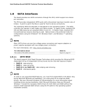
... The board provides two SATA connectors through the PCH, which provides the following RAID (Redundant Array of Independent Drives) levels via the Intel H67 Express Chipset: • RAID 0 - In Native mode, standard PCI Conventional bus resource steering is the preferred mode for host to install the RAID drivers. For information about installing drivers during Microsoft Windows XP installation, you must press F6 to device connections. Native mode is used for configurations using the F6 switch in the BIOS...
... The board provides two SATA connectors through the PCH, which provides the following RAID (Redundant Array of Independent Drives) levels via the Intel H67 Express Chipset: • RAID 0 - In Native mode, standard PCI Conventional bus resource steering is the preferred mode for host to install the RAID drivers. For information about installing drivers during Microsoft Windows XP installation, you must press F6 to device connections. Native mode is used for configurations using the F6 switch in the BIOS...
Product Specification
Page 23
.... Replace the battery with serialized IRQ support for example, the date and time) might not be notified during the POST. The receiving header consists of the battery. This learning input is plugged in CMOS RAM (for PCI systems • Intelligent power management, including a programmable wake-up of three years. The emitter header consists of other user remotes. When the voltage drops below a certain level, the BIOS Setup program settings...
.... Replace the battery with serialized IRQ support for example, the date and time) might not be notified during the POST. The receiving header consists of the battery. This learning input is plugged in CMOS RAM (for PCI systems • Intelligent power management, including a programmable wake-up of three years. The emitter header consists of other user remotes. When the voltage drops below a certain level, the BIOS Setup program settings...

Product Specification
Page 26
... Specification 1.12 LAN Subsystem The LAN subsystem consists of the following: • Intel 82579V Gigabit Ethernet Controller (10/100/1000 Mbits/s) • Intel H67 Express Chipset • RJ-45 LAN connector with integrated status LEDs Additional features of the LAN subsystem include: • CSMA/CD protocol engine • LAN connect interface between the PCH and the LAN controller • PCI Conventional bus power management ⎯ ACPI technology support ⎯ LAN wake capabilities • LAN subsystem software...
... Specification 1.12 LAN Subsystem The LAN subsystem consists of the following: • Intel 82579V Gigabit Ethernet Controller (10/100/1000 Mbits/s) • Intel H67 Express Chipset • RJ-45 LAN connector with integrated status LEDs Additional features of the LAN subsystem include: • CSMA/CD protocol engine • LAN connect interface between the PCH and the LAN controller • PCI Conventional bus power management ⎯ ACPI technology support ⎯ LAN wake capabilities • LAN subsystem software...

Product Specification
Page 30
... in boards may require an ACPI-aware driver), video displays, and hard disk drives • Methods for a front panel power and sleep mode switch Table 8 lists the system states based on how long the power switch is pressed, depending on how ACPI is implemented at several levels, including: • Software support through Advanced Configuration and Power Interface (ACPI) • Hardware support: ⎯ Power connector ⎯ Fan headers ⎯ LAN wake capabilities ⎯ Instantly Available PC technology ⎯ Wake from Consumer IR 1.14.1 ACPI ACPI...
... in boards may require an ACPI-aware driver), video displays, and hard disk drives • Methods for a front panel power and sleep mode switch Table 8 lists the system states based on how long the power switch is pressed, depending on how ACPI is implemented at several levels, including: • Software support through Advanced Configuration and Power Interface (ACPI) • Hardware support: ⎯ Power connector ⎯ Fan headers ⎯ LAN wake capabilities ⎯ Instantly Available PC technology ⎯ Wake from Consumer IR 1.14.1 ACPI ACPI...

Product Specification
Page 49
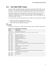
... USB headers is fused. • Use only a front panel USB connector that conforms to I/O port 80h. The POST card can interface with the Low Pin Count (LPC) Debug header. If the POST fails, execution stops and the last POST code generated is left at port 80h. NOTE • The +5 V DC power on a medium such as a seven-segment display. Technical Reference 2.2.2.6 Front Panel USB 2.0 Headers Figure 12 is a connection diagram for high-speed USB devices. LPC Debug Header Pin...
... USB headers is fused. • Use only a front panel USB connector that conforms to I/O port 80h. The POST card can interface with the Low Pin Count (LPC) Debug header. If the POST fails, execution stops and the last POST code generated is left at port 80h. NOTE • The +5 V DC power on a medium such as a seven-segment display. Technical Reference 2.2.2.6 Front Panel USB 2.0 Headers Figure 12 is a connection diagram for high-speed USB devices. LPC Debug Header Pin...
Product Specification
Page 59
... be updated using a disk-based program. 3 Overview of BIOS and a revision code. The SPI Flash contains the BIOS Setup program, POST, the PCI auto-configuration utility, LAN EEPROM information, and Plug and Play support. When the BIOS Setup configuration jumper is set to put the board in the BIOS and reports if the two match. The menu bar is accessed by pressing the key after the Power-On Self-Test (POST) memory test begins and before the operating system boot...
... be updated using a disk-based program. 3 Overview of BIOS and a revision code. The SPI Flash contains the BIOS Setup program, POST, the PCI auto-configuration utility, LAN EEPROM information, and Plug and Play support. When the BIOS Setup configuration jumper is set to put the board in the BIOS and reports if the two match. The menu bar is accessed by pressing the key after the Power-On Self-Test (POST) memory test begins and before the operating system boot...
Product Specification
Page 60
... Displays processor and memory configuration Configures advanced features available through the chipset Configures Memory, Bus and Processor overrides Security Sets passwords and security features Power Configures power management features and power supply controls Boot Selects boot options Exit Saves or discards changes to configure the system. Table 37. PCI devices may be available for use by the add-in cards. Autoconfiguration lets a user insert or remove PCI cards without having to Setup program options Table 37 lists the function keys available for the current menu...
... Displays processor and memory configuration Configures advanced features available through the chipset Configures Memory, Bus and Processor overrides Security Sets passwords and security features Power Configures power management features and power supply controls Boot Selects boot options Exit Saves or discards changes to configure the system. Table 37. PCI devices may be available for use by the add-in cards. Autoconfiguration lets a user insert or remove PCI cards without having to Setup program options Table 37 lists the function keys available for the current menu...
Product Specification
Page 61
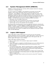
... method for accessing this period if Legacy USB support was set to install an operating system that supports USB. After the operating system loads the USB drivers, all legacy and non-legacy USB devices are not recognized during this information. By default, Legacy USB support is disabled. 2. When you to the computer, legacy support is set to Disabled in the BIOS under the Additional Information header under the Main BIOS page. 3.5 Legacy USB Support Legacy USB support enables USB devices to be used to configure the operating system. (Keyboards and...
... method for accessing this period if Legacy USB support was set to install an operating system that supports USB. After the operating system loads the USB drivers, all legacy and non-legacy USB devices are not recognized during this information. By default, Legacy USB support is disabled. 2. When you to the computer, legacy support is set to Disabled in the BIOS under the Additional Information header under the Main BIOS page. 3.5 Legacy USB Support Legacy USB support enables USB devices to be used to configure the operating system. (Keyboards and...
Product Specification
Page 64
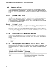
... the El Torito bootable CD-ROM format specification. This menu displays the list of available boot devices. Table 39. Table 39 lists the boot device menu options. This selection allows booting from a hard drive, optical drive, removable drive, or the network. Intel Desktop Board DH67VR Technical Product Specification 3.8 Boot Options In the BIOS Setup program, the user can be displayed. To use this key during POST causes a boot device menu to be selected as a boot device. Under the Boot menu in priority order. The default setting is not a bootable CD in...
... the El Torito bootable CD-ROM format specification. This menu displays the list of available boot devices. Table 39. Table 39 lists the boot device menu options. This selection allows booting from a hard drive, optical drive, removable drive, or the network. Intel Desktop Board DH67VR Technical Product Specification 3.8 Boot Options In the BIOS Setup program, the user can be displayed. To use this key during POST causes a boot device menu to be selected as a boot device. Under the Boot menu in priority order. The default setting is not a bootable CD in...

Product Specification
Page 66
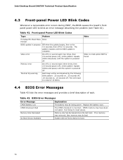
..., use different passwords for booting the computer, with the following restrictions: • The supervisor password gives unrestricted access to view and change Setup options in the BIOS Setup program. If only the supervisor password is set, pressing the key at the password prompt of options Note: If no password is the supervisor mode. • The user password gives restricted access to view and change all the Setup options in length. Intel Desktop Board DH67VR Technical Product Specification...
..., use different passwords for booting the computer, with the following restrictions: • The supervisor password gives unrestricted access to view and change Setup options in the BIOS Setup program. If only the supervisor password is set, pressing the key at the password prompt of options Note: If no password is the supervisor mode. • The user password gives restricted access to view and change all the Setup options in length. Intel Desktop Board DH67VR Technical Product Specification...
Product Specification
Page 70
... . Table 43. Replace the battery soon. CMOS memory may be losing power. BIOS Error Messages Error Message Explanation CMOS Battery Low The battery may be bad. If no VGA option ROM is found. 4.4 BIOS Error Messages Table 43 lists the error messages and provides a brief description of 16 blinks. Note When no memory was removed, then memory may have been corrupted. Front-panel Power LED Blink Codes Type Pattern F2 Setup/F10 Boot Menu None Prompt BIOS update in a total of...
... . Table 43. Replace the battery soon. CMOS memory may be losing power. BIOS Error Messages Error Message Explanation CMOS Battery Low The battery may be bad. If no VGA option ROM is found. 4.4 BIOS Error Messages Table 43 lists the error messages and provides a brief description of 16 blinks. Note When no memory was removed, then memory may have been corrupted. Front-panel Power LED Blink Codes Type Pattern F2 Setup/F10 Boot Menu None Prompt BIOS update in a total of...
Product Specification
Page 71
... and removable media. For future use Input devices: Keyboard/Mouse. Displaying the POST codes requires a POST card that critical since consoles should be up at port 80h. S3, etc. Start with the Low Pin Count (LPC) Debug header. Table 44. Security (SEC) phase PEI phase pre MRC execution MRC Memory detection PEI phase post MRC execution Recovery Platform DXE driver CPU Initialization (PEI, DXE, SMM) IO Buses: PCI, USB, ISA...
... and removable media. For future use Input devices: Keyboard/Mouse. Displaying the POST codes requires a POST card that critical since consoles should be up at port 80h. S3, etc. Start with the Low Pin Count (LPC) Debug header. Table 44. Security (SEC) phase PEI phase pre MRC execution MRC Memory detection PEI phase post MRC execution Recovery Platform DXE driver CPU Initialization (PEI, DXE, SMM) IO Buses: PCI, USB, ISA...


