
Product Specification
Page 8
Back Panel CIR Emitter (Output) Header 44 21. Main Power Connector 46 24. BIOS Setup Program Function Keys 60 38. Front-panel Power LED Blink Codes 70 43. Safety Standards 77 48. Chassis Intrusion ... Compliance Marks 85 viii Environmental Specifications 57 36. Front Panel CIR Receiver (Input) Header 45 22. Thermal Considerations for a One-Color Power LED 48 26. Intel Desktop Board DH67VR Technical Product Specification 18. States for Components 56 34. Recommended Power Supply Current Values (Low Power 53 32. EMC Regulations 81 49...
Back Panel CIR Emitter (Output) Header 44 21. Main Power Connector 46 24. BIOS Setup Program Function Keys 60 38. Front-panel Power LED Blink Codes 70 43. Safety Standards 77 48. Chassis Intrusion ... Compliance Marks 85 viii Environmental Specifications 57 36. Front Panel CIR Receiver (Input) Header 45 22. Thermal Considerations for a One-Color Power LED 48 26. Intel Desktop Board DH67VR Technical Product Specification 18. States for Components 56 34. Recommended Power Supply Current Values (Low Power 53 32. EMC Regulations 81 49...

Product Specification
Page 12
Intel Desktop Board DH67VR Technical Product Specification Table 2 lists the components identified in card connector Back panel connectors Processor core power connector (2 x 2) Rear chassis fan header ... chassis fan header Chassis intrusion header Low Pin Count (LPC) Debug header Consumer IR emitter (output) header Consumer IR receiver (input) header Main power connector (2 x 12) Battery Piezoelectric speaker Intel H67 Express Chipset SATA connectors Front panel header Alternate front panel power LED header BIOS Setup configuration jumper block Front panel USB...
Intel Desktop Board DH67VR Technical Product Specification Table 2 lists the components identified in card connector Back panel connectors Processor core power connector (2 x 2) Rear chassis fan header ... chassis fan header Chassis intrusion header Low Pin Count (LPC) Debug header Consumer IR emitter (output) header Consumer IR receiver (input) header Main power connector (2 x 12) Battery Piezoelectric speaker Intel H67 Express Chipset SATA connectors Front panel header Alternate front panel power LED header BIOS Setup configuration jumper block Front panel USB...
Product Specification
Page 33
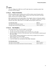
... the power state it was interrupted (on or off the system power through system control. For information about The location of the main power connector The signal names of the main power connector Refer to Figure 10, page 41 Table 23, page 46 1.14.2.2 Fan Headers The function/operation of the fan...
... the power state it was interrupted (on or off the system power through system control. For information about The location of the main power connector The signal names of the main power connector Refer to Figure 10, page 41 Table 23, page 46 1.14.2.2 Fan Headers The function/operation of the fan...
Product Specification
Page 42
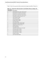
.... Intel Desktop Board DH67VR Technical Product Specification Table 12 lists the component-side connectors and headers identified in card connector E Processor core power connector (2 x 2) F Rear chassis fan header G Processor fan header H Front chassis fan header I Chassis intrusion header J LPC Debug header K Consumer IR emitter (output) header L Consumer IR receiver (input) header M Main...
.... Intel Desktop Board DH67VR Technical Product Specification Table 12 lists the component-side connectors and headers identified in card connector E Processor core power connector (2 x 2) F Rear chassis fan header G Processor fan header H Front chassis fan header I Chassis intrusion header J LPC Debug header K Consumer IR emitter (output) header L Consumer IR receiver (input) header M Main...
Product Specification
Page 46
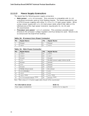
The board supports the use of ATX12V power supplies with a 2 x 10 main power cable, attach that cable on Intel Desktop boards. For information about Power supply considerations Refer to the processor voltage regulator and must always be unconnected. When using a 2 ... detect (Note) 20 No connect 21 +5 V 22 +5 V 23 +5 V (Note) 24 Ground (Note) Note: When using a power supply with either 2 x 10 or 2 x 12 main power cables. Intel Desktop Board DH67VR Technical Product Specification 2.2.2.3 Power Supply Connectors The board has the following power supply connectors: •...
The board supports the use of ATX12V power supplies with a 2 x 10 main power cable, attach that cable on Intel Desktop boards. For information about Power supply considerations Refer to the processor voltage regulator and must always be unconnected. When using a 2 ... detect (Note) 20 No connect 21 +5 V 22 +5 V 23 +5 V (Note) 24 Ground (Note) Note: When using a power supply with either 2 x 10 or 2 x 12 main power cables. Intel Desktop Board DH67VR Technical Product Specification 2.2.2.3 Power Supply Connectors The board has the following power supply connectors: •...
Product Specification
Page 47
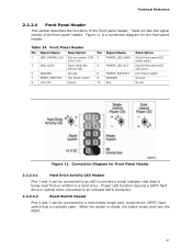
... disk activity LED 5 GROUND Ground 7 RESET_SWITCH# [In] Reset switch 9 +5V_DC Power Pin 2 4 6 8 10 Signal Name POWER_LED_MAIN POWER_LED_ALT POWER_SWITCH# GROUND Key Description [Out] Front panel LED (main color) [Out] Front panel LED (alt color) [In] Power switch Ground No pin Figure 11. Figure 11 is closed, the board resets and runs the...
... disk activity LED 5 GROUND Ground 7 RESET_SWITCH# [In] Reset switch 9 +5V_DC Power Pin 2 4 6 8 10 Signal Name POWER_LED_MAIN POWER_LED_ALT POWER_SWITCH# GROUND Key Description [Out] Front panel LED (main color) [Out] Front panel LED (alt color) [In] Power switch Ground No pin Figure 11. Figure 11 is closed, the board resets and runs the...
Product Specification
Page 48
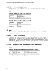
... Front Panel Power/Sleep LED Header Pin Signal Name 1 POWER_LED_MAIN 2 Key (no pin) 3 POWER_LED_ALT Description [Out] Front panel LED (main color) [Out] Front panel LED (alt color) 48 or two-color LED. States for at least 50 ms to signal the power...chassis-specific. 2.2.2.4.4 Power Switch Header Pins 6 and 8 can be connected to a front panel momentary-contact power switch. States for a two-color LED. Intel Desktop Board DH67VR Technical Product Specification 2.2.2.4.3 Power/Sleep LED Header Pins 2 and 4 can be connected to a one -color LED. Table 26 shows the possible...
... Front Panel Power/Sleep LED Header Pin Signal Name 1 POWER_LED_MAIN 2 Key (no pin) 3 POWER_LED_ALT Description [Out] Front panel LED (main color) [Out] Front panel LED (alt color) 48 or two-color LED. States for at least 50 ms to signal the power...chassis-specific. 2.2.2.4.4 Power Switch Header Pins 6 and 8 can be connected to a front panel momentary-contact power switch. States for a two-color LED. Intel Desktop Board DH67VR Technical Product Specification 2.2.2.4.3 Power/Sleep LED Header Pins 2 and 4 can be connected to a one -color LED. Table 26 shows the possible...
Product Specification
Page 59
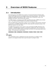
... and reports if the two match. The BIOS displays a message during POST identifying the type of BIOS Features 3.1 Introduction The board uses an Intel BIOS that is stored in configure mode. The BIOS Setup program can be used to view and change the BIOS settings for the computer. Maintenance... Main Configuration Performance Security Power Boot Exit NOTE The maintenance menu is displayed only when the board is in the Serial Peripheral Interface Flash Memory ...
... and reports if the two match. The BIOS displays a message during POST identifying the type of BIOS Features 3.1 Introduction The board uses an Intel BIOS that is stored in configure mode. The BIOS Setup program can be used to view and change the BIOS settings for the computer. Maintenance... Main Configuration Performance Security Power Boot Exit NOTE The maintenance menu is displayed only when the board is in the Serial Peripheral Interface Flash Memory ...
Product Specification
Page 60
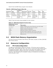
Intel Desktop Board DH67VR Technical Product Specification Table 36 lists the BIOS Setup program menu features. When a user turns on the system after adding a PCI card, ... remove PCI cards without having to Setup program options Table 37 lists the function keys available for menu screens. BIOS Setup Program Menu Bar Maintenance Main Configura- PCI devices may be available for the current menu Save the current values and exits the BIOS Setup program Exits the menu 3.2 BIOS Flash...
Intel Desktop Board DH67VR Technical Product Specification Table 36 lists the BIOS Setup program menu features. When a user turns on the system after adding a PCI card, ... remove PCI cards without having to Setup program options Table 37 lists the function keys available for menu screens. BIOS Setup Program Menu Bar Maintenance Main Configura- PCI devices may be available for the current menu Save the current values and exits the BIOS Setup program Exits the menu 3.2 BIOS Flash...
Product Specification
Page 61
... the SMBIOS information. By default, Legacy USB support is set to Disabled in the BIOS under the Additional Information header under the Main BIOS page. 3.5 Legacy USB Support Legacy USB support enables USB devices to be access by the BIOS allowing you apply power to.... POST begins. 3. POST completes. 5. When you to install an operating system that supports USB. Legacy USB support is enabled by using Intel® Integrator Toolkit. 61 Additional board information can obtain the SMBIOS information. The MIF database defines the data and provides the method for system...
... the SMBIOS information. By default, Legacy USB support is set to Disabled in the BIOS under the Additional Information header under the Main BIOS page. 3.5 Legacy USB Support Legacy USB support enables USB devices to be access by the BIOS allowing you apply power to.... POST begins. 3. POST completes. 5. When you to install an operating system that supports USB. Legacy USB support is enabled by using Intel® Integrator Toolkit. 61 Additional board information can obtain the SMBIOS information. The MIF database defines the data and provides the method for system...