
Product Specification
Page 7
... Summary 11 1.1.2 Board Layout 13 1.1.3 Block Diagram 15 1.2 Legacy Considerations 16 1.3 Online Support 16 1.4 Processor 17 1.4.1 PCI Express x16 Graphics 17 1.5 System Memory 18 1.5.1 Memory Configurations 19 1.6 Intel® P67 Express Chipset 21 1.6.1 USB 21 1.7 SATA Interfaces 22 1.8 Real-Time Clock Subsystem 23 1.9...10 Audio Subsystem 24 1.10.1 Audio Subsystem Software 25 1.10.2 Audio Subsystem Components 25 1.11 LAN Subsystem 26 1.11.1 Intel® 82579V Gigabit Ethernet Controller 26 1.11.2 LAN Subsystem Software 27 1.11.3 RJ-45 LAN Connector with Integrated LEDs 27...
... Summary 11 1.1.2 Board Layout 13 1.1.3 Block Diagram 15 1.2 Legacy Considerations 16 1.3 Online Support 16 1.4 Processor 17 1.4.1 PCI Express x16 Graphics 17 1.5 System Memory 18 1.5.1 Memory Configurations 19 1.6 Intel® P67 Express Chipset 21 1.6.1 USB 21 1.7 SATA Interfaces 22 1.8 Real-Time Clock Subsystem 23 1.9...10 Audio Subsystem 24 1.10.1 Audio Subsystem Software 25 1.10.2 Audio Subsystem Components 25 1.11 LAN Subsystem 26 1.11.1 Intel® 82579V Gigabit Ethernet Controller 26 1.11.2 LAN Subsystem Software 27 1.11.3 RJ-45 LAN Connector with Integrated LEDs 27...

Product Specification
Page 10
...29. Thermal Considerations for a One-Color Power LED 48 25. Front-panel Power LED Blink Codes 70 41. EMC Regulations 81 47. Intel Desktop Board DP67BA Technical Product Specification 18. Front Panel CIR Receiver (Input) Header 45 21. Main Power Connector 46 23. Alternate Front...Header Current Capability 54 31. Acceptable Drives/Media Types for Components 56 33. Tcontrol Values for BIOS Recovery 63 37. Regulatory Compliance Marks 85 x Processor, Front, and Rear Chassis (4-Pin) Fan Headers 44 19. Back Panel CIR Emitter (Output) Header 44 20. States for a Two-Color...
...29. Thermal Considerations for a One-Color Power LED 48 25. Front-panel Power LED Blink Codes 70 41. EMC Regulations 81 47. Intel Desktop Board DP67BA Technical Product Specification 18. Front Panel CIR Receiver (Input) Header 45 21. Main Power Connector 46 23. Alternate Front...Header Current Capability 54 31. Acceptable Drives/Media Types for Components 56 33. Tcontrol Values for BIOS Recovery 63 37. Regulatory Compliance Marks 85 x Processor, Front, and Rear Chassis (4-Pin) Fan Headers 44 19. Back Panel CIR Emitter (Output) Header 44 20. States for a Two-Color...

Product Specification
Page 11
... Chipset ATX (9.60 inches by 11.60 inches [243.84 millimeters by 294.64 millimeters]) • Intel® Core™ i7, Intel® Core™ i5, and Intel Core™ i3 processors with up to 95W TDP in an LGA1155 socket ― One PCI Express* 2.0 x16 graphics interface... Platform Controller Hub (PCH) Graphics Audio Peripheral Interfaces Discrete graphics support for PCI Express 2.0 x16 add-in graphics card 10-channel (7.1 + 2) Intel High Definition Audio via the Realtek ALC892 audio codec • Two USB 3.0 ports are implemented with stacked back panel connectors (blue) • ...
... Chipset ATX (9.60 inches by 11.60 inches [243.84 millimeters by 294.64 millimeters]) • Intel® Core™ i7, Intel® Core™ i5, and Intel Core™ i3 processors with up to 95W TDP in an LGA1155 socket ― One PCI Express* 2.0 x16 graphics interface... Platform Controller Hub (PCH) Graphics Audio Peripheral Interfaces Discrete graphics support for PCI Express 2.0 x16 add-in graphics card 10-channel (7.1 + 2) Intel High Definition Audio via the Realtek ALC892 audio codec • Two USB 3.0 ports are implemented with stacked back panel connectors (blue) • ...
Product Specification
Page 14
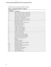
... bus add-in card connector PCI Express x16 bus add-in Figure 1. Intel Desktop Board DP67BA Technical Product Specification Table 2 lists the components identified in card connector Back panel connectors Processor core power connector (2 x 2) Rear chassis fan header LGA1155 processor socket Processor fan header DIMM 3 (Channel A DIMM 0) DIMM 1 (Channel A DIMM 1) DIMM 4 (...(5) Alternate front panel power LED header Front panel header BIOS Setup configuration jumper block Standby power LED Front panel USB 2.0 headers (4) Intel P67 Express Chipset S/PDIF out header Front panel audio header 14
... bus add-in card connector PCI Express x16 bus add-in Figure 1. Intel Desktop Board DP67BA Technical Product Specification Table 2 lists the components identified in card connector Back panel connectors Processor core power connector (2 x 2) Rear chassis fan header LGA1155 processor socket Processor fan header DIMM 3 (Channel A DIMM 0) DIMM 1 (Channel A DIMM 1) DIMM 4 (...(5) Alternate front panel power LED header Front panel header BIOS Setup configuration jumper block Standby power LED Front panel USB 2.0 headers (4) Intel P67 Express Chipset S/PDIF out header Front panel audio header 14
Product Specification
Page 16
...=hdr+support http://ark.intel.com Supported processors Chipset information BIOS and driver updates Tested memory Integration information http://processormatch.intel.com http://www.intel.com/products/desktop/chipsets/index.htm http://downloadcenter.intel.com http://www.intel.com/support/motherboards/desktop/sb/CS025414.htm http://www.intel.com/support/go/buildit 16 Intel Desktop Board DP67BA Technical...
...=hdr+support http://ark.intel.com Supported processors Chipset information BIOS and driver updates Tested memory Integration information http://processormatch.intel.com http://www.intel.com/products/desktop/chipsets/index.htm http://downloadcenter.intel.com http://www.intel.com/support/motherboards/desktop/sb/CS025414.htm http://www.intel.com/support/go/buildit 16 Intel Desktop Board DP67BA Technical...

Product Specification
Page 17
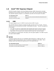
... Section 2.5.1 on page 53 for information on power supply requirements for this board. 1.4.1 PCI Express x16 Graphics The Intel Core i7, Intel Core i5, and Intel Core i3 processors in an LGA1155 socket support discrete add in graphics cards via the PCI Express 2.0 x16 graphics connector: •...MB/s) per lane. Refer to support the Intel Core i7, Intel Core i5, and Intel Core i3 processors in an LGA1155 socket Other processors may be supported in the future. This board is designed to : http://processormatch.intel.com CAUTION Use only the processors listed on the web site above are ...
... Section 2.5.1 on page 53 for information on power supply requirements for this board. 1.4.1 PCI Express x16 Graphics The Intel Core i7, Intel Core i5, and Intel Core i3 processors in an LGA1155 socket support discrete add in graphics cards via the PCI Express 2.0 x16 graphics connector: •...MB/s) per lane. Refer to support the Intel Core i7, Intel Core i5, and Intel Core i3 processors in an LGA1155 socket Other processors may be supported in the future. This board is designed to : http://processormatch.intel.com CAUTION Use only the processors listed on the web site above are ...

Product Specification
Page 19
... channel bandwidth operation for each channel must be equal. For information about... Product Description 1.5.1 Memory Configurations The Intel Core i7, Intel Core i5, and Intel Core i3 processors in multiple zones of dual and single channel operation across the whole of memory organization: • Dual channel... provides the most flexible performance characteristics. This mode is used when only a single DIMM is necessary to : http://www.intel.com/support/motherboards/desktop/sb/cs011965.htm 19 Flex mode results in the LGA1155 socket support the following types of DRAM memory...
... channel bandwidth operation for each channel must be equal. For information about... Product Description 1.5.1 Memory Configurations The Intel Core i7, Intel Core i5, and Intel Core i3 processors in multiple zones of dual and single channel operation across the whole of memory organization: • Dual channel... provides the most flexible performance characteristics. This mode is used when only a single DIMM is necessary to : http://www.intel.com/support/motherboards/desktop/sb/cs011965.htm 19 Flex mode results in the LGA1155 socket support the following types of DRAM memory...

Product Specification
Page 20
Figure 3. For best memory performance always install memory into the blue DIMM memory sockets if only installing two DIMMs in the DIMM 1 (Channel A, DIMM 0) socket. Memory Channel and DIMM Configuration NOTE The Intel Core i7, Intel Core i5, and Intel Core i3 processors require memory to be populated in your configuration. 20 Intel Desktop Board DP67BA Technical Product Specification Figure 3 illustrates the memory channel and DIMM configuration.
Figure 3. For best memory performance always install memory into the blue DIMM memory sockets if only installing two DIMMs in the DIMM 1 (Channel A, DIMM 0) socket. Memory Channel and DIMM Configuration NOTE The Intel Core i7, Intel Core i5, and Intel Core i3 processors require memory to be populated in your configuration. 20 Intel Desktop Board DP67BA Technical Product Specification Figure 3 illustrates the memory channel and DIMM configuration.
Product Specification
Page 21
...panel connectors (blue) • Six USB 2.0 ports are implemented with Direct Media Interface (DMI) interconnect provides interfaces to the cable. The Intel P67 Express Chipset provides the USB controller for the board's I/O paths. The two USB 3.0 ports are super-speed capable. The port ...arrangement is attached to the processor and the USB, SATA, LPC, LAN, and PCI Express interfaces. For information about The Intel P67 chipset Resources used by the NEC* UPD720200 controller. NOTES Computer systems that meets the ...
...panel connectors (blue) • Six USB 2.0 ports are implemented with Direct Media Interface (DMI) interconnect provides interfaces to the cable. The Intel P67 Express Chipset provides the USB controller for the board's I/O paths. The two USB 3.0 ports are super-speed capable. The port ...arrangement is attached to the processor and the USB, SATA, LPC, LAN, and PCI Express interfaces. For information about The Intel P67 chipset Resources used by the NEC* UPD720200 controller. NOTES Computer systems that meets the ...
Product Specification
Page 28
...8226; SMBus interface 1.12.2 Fan Monitoring Fan monitoring can be compatible with the Wired for Management (WfM) specification. Intel Desktop Board DP67BA Technical Product Specification 1.12 Hardware Management Subsystem The hardware management features enable the board to be implemented using... Intel® Desktop Utilities or third-party software. The board has several hardware management features, including the following : • Processor and system ambient temperature monitoring • Chassis fan speed ...
...8226; SMBus interface 1.12.2 Fan Monitoring Fan monitoring can be compatible with the Wired for Management (WfM) specification. Intel Desktop Board DP67BA Technical Product Specification 1.12 Hardware Management Subsystem The hardware management features enable the board to be implemented using... Intel® Desktop Utilities or third-party software. The board has several hardware management features, including the following : • Processor and system ambient temperature monitoring • Chassis fan speed ...
Product Specification
Page 29
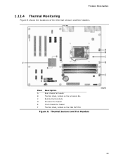
Item A B C D E F Description Rear chassis fan header Thermal diode, located on the processor die Remote thermal diode Processor fan header Front chassis fan header Thermal diode, located on the Intel P67 PCH Figure 6. Product Description 1.12.4 Thermal Monitoring Figure 6 shows the locations of the thermal sensors and fan headers. Thermal Sensors and Fan Headers 29
Item A B C D E F Description Rear chassis fan header Thermal diode, located on the processor die Remote thermal diode Processor fan header Front chassis fan header Thermal diode, located on the Intel P67 PCH Figure 6. Product Description 1.12.4 Thermal Monitoring Figure 6 shows the locations of the thermal sensors and fan headers. Thermal Sensors and Fan Headers 29

Product Specification
Page 31
... saved to RAM. Power < 5 W (Note 2) G3 - No power to disk. Service can be performed safely. Power States and Targeted System Power Global States Sleeping States Processor States Device States Targeted System Power (Note 1) G0 - sleeping state S3 - no power except for wake-up logic. Power < 5 W (Note 2) Power < 5 W (Note 2) G2/S5 S5...
... saved to RAM. Power < 5 W (Note 2) G3 - No power to disk. Service can be performed safely. Power States and Targeted System Power Global States Sleeping States Processor States Device States Targeted System Power (Note 1) G0 - sleeping state S3 - no power except for wake-up logic. Power < 5 W (Note 2) Power < 5 W (Note 2) G2/S5 S5...

Product Specification
Page 42
Intel Desktop Board DP67BA Technical Product Specification Table 10 lists the component-side connectors and headers identified in card connector H Processor core power connector (2 x 2) I Rear chassis fan header J Processor fan header K Front chassis fan header L Chassis intrusion header M LPC Debug header N Consumer IR emitter (output) header O Consumer IR receiver (input) header P Main power connector...
Intel Desktop Board DP67BA Technical Product Specification Table 10 lists the component-side connectors and headers identified in card connector H Processor core power connector (2 x 2) I Rear chassis fan header J Processor fan header K Front chassis fan header L Chassis intrusion header M LPC Debug header N Consumer IR emitter (output) header O Consumer IR receiver (input) header P Main power connector...

Product Specification
Page 44
... Table 18. Table 19. Back Panel CIR Emitter (Output) Header Pin Signal Name 1 Emitter out 1 2 Emitter out 2 3 Ground 4 Key (no pin) 4 +5 V DC Table 17. Processor, Front, and Rear Chassis (4-Pin) Fan Headers Pin 1 2 3 Signal Name Ground (Note) +12 V FAN_TACH 4 FAN_CONTROL Note: These fan headers use Pulse Width Modulation control for... fan speed. S/PDIF Header Pin Signal Name 1 Ground 2 S/PDIF out 3 Key (no pin) 5 Jack detect 1 6 Jack detect 2 44 Intel Desktop Board DP67BA Technical Product Specification Table 15.
... Table 18. Table 19. Back Panel CIR Emitter (Output) Header Pin Signal Name 1 Emitter out 1 2 Emitter out 2 3 Ground 4 Key (no pin) 4 +5 V DC Table 17. Processor, Front, and Rear Chassis (4-Pin) Fan Headers Pin 1 2 3 Signal Name Ground (Note) +12 V FAN_TACH 4 FAN_CONTROL Note: These fan headers use Pulse Width Modulation control for... fan speed. S/PDIF Header Pin Signal Name 1 Ground 2 S/PDIF out 3 Key (no pin) 5 Jack detect 1 6 Jack detect 2 44 Intel Desktop Board DP67BA Technical Product Specification Table 15.
Product Specification
Page 46
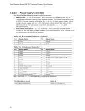
..., this pin will prevent the board from booting. This connector provides power directly to do so will be used on page 53 46 Table 21. Processor Core Power Connector Pin Signal Name Pin Signal Name 1 Ground 3 +12 V 2 Ground 4 +12 V Table 22. a 2 x 2 ... 12, 23, and 24 unconnected. • Processor core power - Failure to the processor voltage regulator and must always be unconnected. For information about Power supply considerations Refer to Section 2.5.1 on Intel Desktop boards. Intel Desktop Board DP67BA Technical Product Specification 2.2.2.3 Power Supply ...
..., this pin will prevent the board from booting. This connector provides power directly to do so will be used on page 53 46 Table 21. Processor Core Power Connector Pin Signal Name Pin Signal Name 1 Ground 3 +12 V 2 Ground 4 +12 V Table 22. a 2 x 2 ... 12, 23, and 24 unconnected. • Processor core power - Failure to the processor voltage regulator and must always be unconnected. For information about Power supply considerations Refer to Section 2.5.1 on Intel Desktop boards. Intel Desktop Board DP67BA Technical Product Specification 2.2.2.3 Power Supply ...
Product Specification
Page 50
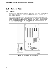
...the location of the Jumper Block 50 When the jumper is set to configure mode and the computer is powered-up, the BIOS compares the processor version and the microcode version in the BIOS and reports if the two match. Always turn off the power and unplug the power cord from.... Table 28 describes the jumper settings for the three modes: normal, configure, and recovery. The 3-pin jumper block determines the BIOS Setup program's mode. Intel Desktop Board DP67BA Technical Product Specification 2.3 Jumper Block CAUTION Do not move the jumper with the power on. Location of the jumper block.
...the location of the Jumper Block 50 When the jumper is set to configure mode and the computer is powered-up, the BIOS compares the processor version and the microcode version in the BIOS and reports if the two match. Always turn off the power and unplug the power cord from.... Table 28 describes the jumper settings for the three modes: normal, configure, and recovery. The 3-pin jumper block determines the BIOS Setup program's mode. Intel Desktop Board DP67BA Technical Product Specification 2.3 Jumper Block CAUTION Do not move the jumper with the power on. Location of the jumper block.

Product Specification
Page 53
Failure to http://support.intel.com/support/motherboards/desktop/sb /CS-026472.htm 53 The total amount of standby current required depends on configurations chosen by the integrator. Table 29 ... of the +5 VSB line • All timing parameters • All voltage tolerances For example, for a system consisting of a supported 95 W processor (see Section 1.4 on page 17 for a list of supported processors), 1 GB DDR3 RAM, one high end video card, one hard disk drive, one optical drive, and all board peripherals enabled, the...
Failure to http://support.intel.com/support/motherboards/desktop/sb /CS-026472.htm 53 The total amount of standby current required depends on configurations chosen by the integrator. Table 29 ... of the +5 VSB line • All timing parameters • All voltage tolerances For example, for a system consisting of a supported 95 W processor (see Section 1.4 on page 17 for a list of supported processors), 1 GB DDR3 RAM, one high end video card, one hard disk drive, one optical drive, and all board peripherals enabled, the...
Product Specification
Page 54
... instances, damage to the following the instructions presented in this document will halt fan operation. Connecting the processor fan to a chassis fan header. Intel Desktop Board DP67BA Technical Product Specification 2.5.2 Fan Header Current Capability CAUTION The processor fan must not exceed the system's power supply of +5 V maximum current or 14 A in total. 2.6 Thermal...
... instances, damage to the following the instructions presented in this document will halt fan operation. Connecting the processor fan to a chassis fan header. Intel Desktop Board DP67BA Technical Product Specification 2.5.2 Fan Header Current Capability CAUTION The processor fan must not exceed the system's power supply of +5 V maximum current or 14 A in total. 2.6 Thermal...
Product Specification
Page 55
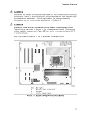
...) can reach a temperature of the localized high temperature zones. CAUTION Ensure that the ambient temperature does not exceed the board's maximum operating temperature. Item A B C Description Processor voltage regulator area Processor Intel P67 Express Chipset Figure 15. Failure to exceed their maximum case temperature and malfunction. The...
...) can reach a temperature of the localized high temperature zones. CAUTION Ensure that the ambient temperature does not exceed the board's maximum operating temperature. Item A B C Description Processor voltage regulator area Processor Intel P67 Express Chipset Figure 15. Failure to exceed their maximum case temperature and malfunction. The...
Product Specification
Page 56
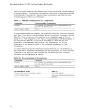
.../products/desktop/ chipsets/ 56 The surface temperature at or below the Maximum Case Temperature. Tcontrol Values for Components Component Tcontrol Processor For processor case temperature, see processor datasheets and processor specification updates Intel P67 Express Chipset 104 oC To ensure functionality and reliability, the component is specified for proper operation when Case Temperature is Tcontrol...
.../products/desktop/ chipsets/ 56 The surface temperature at or below the Maximum Case Temperature. Tcontrol Values for Components Component Tcontrol Processor For processor case temperature, see processor datasheets and processor specification updates Intel P67 Express Chipset 104 oC To ensure functionality and reliability, the component is specified for proper operation when Case Temperature is Tcontrol...


