
Product Specification
Page 5
... 1.4 Processor 14 1.5 Intel® Q67 Express Chipset 15 1.6 System Memory 15 1.6.1 Memory Configurations 16 1.7 Graphics Subsystem 18 1.7.1 Integrated Graphics 18 1.7.2 PCI Express x16 Graphics 19 1.8 USB 19 1.9 SATA Interfaces 20 1.10 Legacy I/O Controller 21 1.10.1 Serial Port 21 1.11 Audio Subsystem 22 1.11.1 Audio Subsystem Software 22 1.11.2 Audio Headers and Connectors 22 1.12 LAN Subsystem 24 1.12.1 Intel® 82579LM Gigabit Ethernet Controller 24 1.12.2 LAN Subsystem Software 24 1.12.3 RJ-45 LAN Connector with Integrated LEDs 25 1.13 Real-Time Clock...
... 1.4 Processor 14 1.5 Intel® Q67 Express Chipset 15 1.6 System Memory 15 1.6.1 Memory Configurations 16 1.7 Graphics Subsystem 18 1.7.1 Integrated Graphics 18 1.7.2 PCI Express x16 Graphics 19 1.8 USB 19 1.9 SATA Interfaces 20 1.10 Legacy I/O Controller 21 1.10.1 Serial Port 21 1.11 Audio Subsystem 22 1.11.1 Audio Subsystem Software 22 1.11.2 Audio Headers and Connectors 22 1.12 LAN Subsystem 24 1.12.1 Intel® 82579LM Gigabit Ethernet Controller 24 1.12.2 LAN Subsystem Software 24 1.12.3 RJ-45 LAN Connector with Integrated LEDs 25 1.13 Real-Time Clock...

Product Specification
Page 6
... System Management BIOS (SMBIOS 65 3.3 Legacy USB Support 65 3.4 BIOS Updates 66 3.4.1 Language Support 66 3.4.2 Custom Splash Screen 67 3.5 BIOS Recovery 67 3.6 Boot Options 68 3.6.1 Optical Drive Boot 68 3.6.2 Network Boot 68 3.6.3 Booting Without Attached Devices 68 3.6.4 Changing the Default Boot Device During POST 68 3.7 Hard Disk Drive Password Security Feature 69 3.8 BIOS Security Features 70 4 Error Messages and Beep Codes 4.1 Speaker 73 4.2 BIOS Beep Codes 73 4.3 Front-panel Power LED Blink Codes 74 4.4 BIOS Error Messages 74 4.5 Port 80h POST Codes 75 5 Regulatory...
... System Management BIOS (SMBIOS 65 3.3 Legacy USB Support 65 3.4 BIOS Updates 66 3.4.1 Language Support 66 3.4.2 Custom Splash Screen 67 3.5 BIOS Recovery 67 3.6 Boot Options 68 3.6.1 Optical Drive Boot 68 3.6.2 Network Boot 68 3.6.3 Booting Without Attached Devices 68 3.6.4 Changing the Default Boot Device During POST 68 3.7 Hard Disk Drive Password Security Feature 69 3.8 BIOS Security Features 70 4 Error Messages and Beep Codes 4.1 Speaker 73 4.2 BIOS Beep Codes 73 4.3 Front-panel Power LED Blink Codes 74 4.4 BIOS Error Messages 74 4.5 Port 80h POST Codes 75 5 Regulatory...

Product Specification
Page 7
... Power LED Header 52 26. SATA Connectors 48 17. Front Panel IEEE 1394a Header 49 21. Intel MEBX Reset Header Signals 56 vii Component-side Connectors and Headers Shown in Figure 1 12 3. Main Power Connector 50 23. Supported Memory Configurations 16 4. Effects of the Standby Power LED (Green 40 8. Connection Diagram for Front Panel Header 51 12. Internal Mono Speaker Header 47 13. Contents Figures 1. Wake-up Devices and Events 36 8. Location of the Jumper Block 54 14. BIOS Setup Configuration Jumper Settings 55 27. LAN Connector LED Locations 25 6. Processor (4-Pin...
... Power LED Header 52 26. SATA Connectors 48 17. Front Panel IEEE 1394a Header 49 21. Intel MEBX Reset Header Signals 56 vii Component-side Connectors and Headers Shown in Figure 1 12 3. Main Power Connector 50 23. Supported Memory Configurations 16 4. Effects of the Standby Power LED (Green 40 8. Connection Diagram for Front Panel Header 51 12. Internal Mono Speaker Header 47 13. Contents Figures 1. Wake-up Devices and Events 36 8. Location of the Jumper Block 54 14. BIOS Setup Configuration Jumper Settings 55 27. LAN Connector LED Locations 25 6. Processor (4-Pin...

Product Specification
Page 8
... Recommended Power Supply Current Values 58 29. Environmental Specifications 62 32. Master Key and User Hard Drive Password Functions 69 37. Front-panel Power LED Blink Codes 74 40. Typical Port 80h POST Sequence 80 44. BIOS Error Messages 74 41. Fan Header Current Capability 59 30. Thermal Considerations for BIOS Recovery 67 35. BIOS Setup Program Function Keys 64 34. Safety Standards 81 45. Supervisor and User Password Functions 71 38. Boot Device Menu Options 68 36. Port 80h POST Code...
... Recommended Power Supply Current Values 58 29. Environmental Specifications 62 32. Master Key and User Hard Drive Password Functions 69 37. Front-panel Power LED Blink Codes 74 40. Typical Port 80h POST Sequence 80 44. BIOS Error Messages 74 41. Fan Header Current Capability 59 30. Thermal Considerations for BIOS Recovery 67 35. BIOS Setup Program Function Keys 64 34. Safety Standards 81 45. Supervisor and User Password Functions 71 38. Boot Device Menu Options 68 36. Port 80h POST Code...

Product Specification
Page 10
Intel Desktop Board DQ67SW Technical Product Specification Table 1. Feature Summary (continued) Peripheral Interfaces Legacy I/O Control BIOS Instantly Available PC Technology • Fourteen USB ports: ― Two USB 3.0 ports are implemented with stacked back panel connectors (blue) ― Four USB 2.0 ports are implemented with stacked back panel connectors (black) ― Eight USB 2.0 front panel ports are implemented through four dual-port internal headers • Six SATA interfaces through the Intel Q67 Express Chipset with Intel® Rapid Storage Technology RAID support: &#...
Intel Desktop Board DQ67SW Technical Product Specification Table 1. Feature Summary (continued) Peripheral Interfaces Legacy I/O Control BIOS Instantly Available PC Technology • Fourteen USB ports: ― Two USB 3.0 ports are implemented with stacked back panel connectors (blue) ― Four USB 2.0 ports are implemented with stacked back panel connectors (black) ― Eight USB 2.0 front panel ports are implemented through four dual-port internal headers • Six SATA interfaces through the Intel Q67 Express Chipset with Intel® Rapid Storage Technology RAID support: &#...

Product Specification
Page 12
...header Q Battery R Front chassis fan header S Main power connector (2 x 12) T Standby power LED U Piezoelectric speaker V Intel Q67 Express Chipset W Alternate front panel power LED header X Front panel header Y BIOS setup configuration jumper block Z Intel® Management Engine BIOS Extension (Intel® MEBX) Reset header AA SATA connectors BB Intel Fast Call for Help (Intel FCFH) header CC Front panel USB headers (4) DD IEEE 1394a front panel header EE S/PDIF header FF Rear chassis fan header 12 Intel Desktop Board DQ67SW Technical Product Specification...
...header Q Battery R Front chassis fan header S Main power connector (2 x 12) T Standby power LED U Piezoelectric speaker V Intel Q67 Express Chipset W Alternate front panel power LED header X Front panel header Y BIOS setup configuration jumper block Z Intel® Management Engine BIOS Extension (Intel® MEBX) Reset header AA SATA connectors BB Intel Fast Call for Help (Intel FCFH) header CC Front panel USB headers (4) DD IEEE 1394a front panel header EE S/PDIF header FF Rear chassis fan header 12 Intel Desktop Board DQ67SW Technical Product Specification...

Product Specification
Page 14
...: • No floppy drive connector • No PS/2 connector • No Parallel ATA (PATA) IDE drive connector 1.3 Online Support To find information about ... For information about ... Intel Desktop Board DQ67SW Desktop Board Support Available configurations for the Intel Desktop Board DQ67SW Visit this World Wide Web site: http://www.intel.com/products/motherboard/index.htm http://www.intel.com/p/en_US/support?iid=hdr+support http://ark.intel.com Supported processors Chipset information BIOS and driver updates Tested memory Integration information http...
...: • No floppy drive connector • No PS/2 connector • No Parallel ATA (PATA) IDE drive connector 1.3 Online Support To find information about ... For information about ... Intel Desktop Board DQ67SW Desktop Board Support Available configurations for the Intel Desktop Board DQ67SW Visit this World Wide Web site: http://www.intel.com/products/motherboard/index.htm http://www.intel.com/p/en_US/support?iid=hdr+support http://ark.intel.com Supported processors Chipset information BIOS and driver updates Tested memory Integration information http...

Product Specification
Page 15
... processor and the USB, SATA, LPC, audio, network, display, Conventional PCI, and PCI Express. Refer to Section 2.1.1 on page 41 for information on the total amount of the Intel Q67 Platform Controller Hub (PCH) provides interfaces to http://www.intel.com/products/desktop/chipsets/index.htm Chapter 2 1.6 System Memory The board has four DIMM sockets and supports the following memory features: • Two independent memory channels with interleaved mode support • Supports 1.2 V - 1.8 V DIMM memory voltage • Support...
... processor and the USB, SATA, LPC, audio, network, display, Conventional PCI, and PCI Express. Refer to Section 2.1.1 on page 41 for information on the total amount of the Intel Q67 Platform Controller Hub (PCH) provides interfaces to http://www.intel.com/products/desktop/chipsets/index.htm Chapter 2 1.6 System Memory The board has four DIMM sockets and supports the following memory features: • Two independent memory channels with interleaved mode support • Supports 1.2 V - 1.8 V DIMM memory voltage • Support...
Product Specification
Page 19
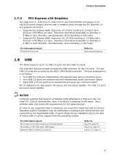
...mode. • Supports PCI Express GEN1 frequency of native USB 3.0 driver support from the operating system. For information about PCI Express technology Refer to http://www.pcisig.com 1.8 USB The board supports up to use supported USB 3.0 features, you must first install the USB 3.0 drivers. The USB 3.0 ports are connected to the SuperSpeed USB 3.0 ports (blue) during installation due to the cable. Product Description 1.7.2 PCI Express x16 Graphics The Intel Core i7, Intel Core i5, Intel Core i3, and Intel Pentium processors in an LGA1155 socket support discrete add in graphics cards...
...mode. • Supports PCI Express GEN1 frequency of native USB 3.0 driver support from the operating system. For information about PCI Express technology Refer to http://www.pcisig.com 1.8 USB The board supports up to use supported USB 3.0 features, you must first install the USB 3.0 drivers. The USB 3.0 ports are connected to the SuperSpeed USB 3.0 ports (blue) during installation due to the cable. Product Description 1.7.2 PCI Express x16 Graphics The Intel Core i7, Intel Core i5, Intel Core i3, and Intel Pentium processors in an LGA1155 socket support discrete add in graphics cards...

Product Specification
Page 20
... installation. For information about installing drivers during Microsoft Windows XP installation, you must press F6 to Figure 10, page 45 1.9.1.1 Serial ATA RAID The board supports the Intel Rapid Storage Technology (Intel RST) which support one device per connector: • Two internal SATA 6 Gb/s ports (blue) • Two internal SATA 3 Gb/s ports (black) • Two backpanel eSATA 3 Gb/s ports for external connectivity (red) The PCH provides independent SATA ports with a theoretical maximum transfer rate of Independent Drives...
... installation. For information about installing drivers during Microsoft Windows XP installation, you must press F6 to Figure 10, page 45 1.9.1.1 Serial ATA RAID The board supports the Intel Rapid Storage Technology (Intel RST) which support one device per connector: • Two internal SATA 6 Gb/s ports (blue) • Two internal SATA 3 Gb/s ports (black) • Two backpanel eSATA 3 Gb/s ports for external connectivity (red) The PCH provides independent SATA ports with a theoretical maximum transfer rate of Independent Drives...

Product Specification
Page 31
... software applications. If using simultaneous integrated graphics and add-in PCI Express Graphics, Integrated Graphics Device (IGD) must be seen during off hours, improving security and performance of the platform. Product Description • KVM (Keyboard-Video-Mouse) Remote Control allows an IT administrator to remotely control a user's keyboard without having to rely on -screen pop-up windows. The package usually consists of an Intel® processor with integrated graphics...
... software applications. If using simultaneous integrated graphics and add-in PCI Express Graphics, Integrated Graphics Device (IGD) must be seen during off hours, improving security and performance of the platform. Product Description • KVM (Keyboard-Video-Mouse) Remote Control allows an IT administrator to remotely control a user's keyboard without having to rely on -screen pop-up windows. The package usually consists of an Intel® processor with integrated graphics...
Product Specification
Page 53
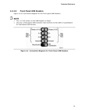
Connection Diagram for the front panel USB headers. Technical Reference 2.2.2.6 Front Panel USB Headers Figure 12 is fused. • Use only a front panel USB connector that conforms to the USB 2.0 specification for high-speed USB devices. Figure 12. NOTE • The +5 V DC power on the USB headers is a connection diagram for Front Panel USB Headers 53
Connection Diagram for the front panel USB headers. Technical Reference 2.2.2.6 Front Panel USB Headers Figure 12 is fused. • Use only a front panel USB connector that conforms to the USB 2.0 specification for high-speed USB devices. Figure 12. NOTE • The +5 V DC power on the USB headers is a connection diagram for Front Panel USB Headers 53
Product Specification
Page 55
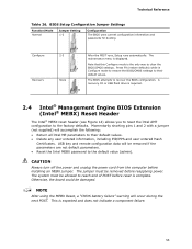
...Configure mode is complete. The BIOS attempts to clear the BIOS/CMOS settings. This is displayed. Otherwise, the board could be allowed to the factory defaults. The maintenance menu is expected and does not indicate a component failure. 55 BIOS Setup Configuration Jumper Settings Function/Mode Normal Jumper Setting 1-2 Configuration The BIOS uses current configuration information and passwords for booting. A recovery CD or USB flash drive is required. 2.4 Intel® Management Engine BIOS Extension (Intel® MEBX) Reset Header The Intel® MEBX reset header...
...Configure mode is complete. The BIOS attempts to clear the BIOS/CMOS settings. This is displayed. Otherwise, the board could be allowed to the factory defaults. The maintenance menu is expected and does not indicate a component failure. 55 BIOS Setup Configuration Jumper Settings Function/Mode Normal Jumper Setting 1-2 Configuration The BIOS uses current configuration information and passwords for booting. A recovery CD or USB flash drive is required. 2.4 Intel® Management Engine BIOS Extension (Intel® MEBX) Reset Header The Intel® MEBX reset header...

Product Specification
Page 63
... Flash Memory (SPI Flash) device which can be updated using a set of utilities. This is due to the fact that is shown below. 3 Overview of BIOS Features 3.1 Introduction The board uses an Intel BIOS that Chipset-SATA Mode now defaults to AHCI. 63 The BIOS displays a message during POST identifying the type of BIOS and a revision code. The BIOS Setup program is in the system becoming unbootable or corrupting the HDD if RAID is used to view and change the BIOS settings...
... Flash Memory (SPI Flash) device which can be updated using a set of utilities. This is due to the fact that is shown below. 3 Overview of BIOS Features 3.1 Introduction The board uses an Intel BIOS that Chipset-SATA Mode now defaults to AHCI. 63 The BIOS displays a message during POST identifying the type of BIOS and a revision code. The BIOS Setup program is in the system becoming unbootable or corrupting the HDD if RAID is used to view and change the BIOS settings...

Product Specification
Page 65
... network. POST completes. 5. Additional board information can be used to configure the operating system. (Keyboards and mice are not recognized during this period if Legacy USB support was set to Enabled. Overview of SMBIOS is set to Disabled in the BIOS under the Additional Information header under the Main BIOS page. 3.3 Legacy USB Support Legacy USB support enables USB devices to be used even when the operating system's USB drivers are recognized by the BIOS allowing you apply power to use a USB keyboard to install...
... network. POST completes. 5. Additional board information can be used to configure the operating system. (Keyboards and mice are not recognized during this period if Legacy USB support was set to Enabled. Overview of SMBIOS is set to Disabled in the BIOS under the Additional Information header under the Main BIOS page. 3.3 Legacy USB Support Legacy USB support enables USB devices to be used even when the operating system's USB drivers are recognized by the BIOS allowing you apply power to use a USB keyboard to install...
Product Specification
Page 68
... Changing the Default Boot Device During POST Pressing the key during POST, the User Access Level in card with a remote boot ROM installed. This menu displays the list of available boot devices. Table 35 lists the boot device menu options. Accordingly, if there is listed as a boot device. Boot Device Menu Options Boot Device Menu Function Keys or Description Selects a default boot device Exits the menu, and boots from the next defined drive. 3.6.2 Network Boot The network can choose to the boot priority defined through BIOS setup 68 Intel Desktop Board DQ67SW...
... Changing the Default Boot Device During POST Pressing the key during POST, the User Access Level in card with a remote boot ROM installed. This menu displays the list of available boot devices. Table 35 lists the boot device menu options. Accordingly, if there is listed as a boot device. Boot Device Menu Options Boot Device Menu Function Keys or Description Selects a default boot device Exits the menu, and boots from the next defined drive. 3.6.2 Network Boot The network can choose to the boot priority defined through BIOS setup 68 Intel Desktop Board DQ67SW...

Product Specification
Page 69
The Master Key hard disk drive password, when installed, will have three attempts to correctly enter the hard disk drive password. Master Key and User Hard Drive Password Functions Password Set Password During Boot Neither None Master only None User only User only Master and User Set Master or User During every POST, if a User hard disk drive password is set in the event that does not support Hard Disk Drive Password Security feature, the drive will not be required upon a system power-cycle. After the third unsuccessful hard disk drive password attempt, the...
The Master Key hard disk drive password, when installed, will have three attempts to correctly enter the hard disk drive password. Master Key and User Hard Drive Password Functions Password Set Password During Boot Neither None Master only None User only User only Master and User Set Master or User During every POST, if a User hard disk drive password is set in the event that does not support Hard Disk Drive Password Security feature, the drive will not be required upon a system power-cycle. After the third unsuccessful hard disk drive password attempt, the...

Product Specification
Page 70
..., use different passwords for the supervisor and user passwords. • Valid password characters are A-Z, a-z, and 0-9. A supervisor password and a user password can boot the computer. Intel Desktop Board DQ67SW Technical Product Specification NOTE Hard Disk Drive Password Security is not supported in length. 70 Secured hard disk drives attached to the BIOS Setup program and who can be accessible due to the disabling of the BIOS Setup program allows the user restricted access to Setup. • If both passwords are set , pressing the key...
..., use different passwords for the supervisor and user passwords. • Valid password characters are A-Z, a-z, and 0-9. A supervisor password and a user password can boot the computer. Intel Desktop Board DQ67SW Technical Product Specification NOTE Hard Disk Drive Password Security is not supported in length. 70 Secured hard disk drives attached to the BIOS Setup program and who can be accessible due to the disabling of the BIOS Setup program allows the user restricted access to Setup. • If both passwords are set , pressing the key...

Product Specification
Page 74
... power. Front-panel Power LED Blink Codes Type Pattern F2 Setup/F10 Boot Menu None Prompt BIOS update in graphics card 4.4 BIOS Error Messages Table 40 lists the error messages and provides a brief description of 16 blinks. The pattern repeats until the BIOS update is incorrect. Memory Size Decreased Memory size has decreased since the last boot. Table 40. BIOS Error Messages Error Message Explanation CMOS Battery Low The battery may be bad. Replace the battery soon. Table 39. Video error (no memory was removed, then memory...
... power. Front-panel Power LED Blink Codes Type Pattern F2 Setup/F10 Boot Menu None Prompt BIOS update in graphics card 4.4 BIOS Error Messages Table 40 lists the error messages and provides a brief description of 16 blinks. The pattern repeats until the BIOS update is incorrect. Memory Size Decreased Memory size has decreased since the last boot. Table 40. BIOS Error Messages Error Message Explanation CMOS Battery Low The battery may be bad. Replace the battery soon. Table 39. Video error (no memory was removed, then memory...

Product Specification
Page 75
... MRC execution MRC memory detection PEI phase post MRC execution Recovery Platform DXE driver CPU Initialization (PEI, DXE, SMM) I /O port 80h. For future use For future use Boot Devices: Includes fixed media and removable media. For future use Input devices: Keyboard/Mouse. Resuming from SX states. 0x10 -0x20 - Error Messages and Beep Codes 4.5 Port 80h POST Codes During the POST, the BIOS generates diagnostic progress codes (POST codes) to S5. NOTE The POST card must be up...
... MRC execution MRC memory detection PEI phase post MRC execution Recovery Platform DXE driver CPU Initialization (PEI, DXE, SMM) I /O port 80h. For future use For future use Boot Devices: Includes fixed media and removable media. For future use Input devices: Keyboard/Mouse. Resuming from SX states. 0x10 -0x20 - Error Messages and Beep Codes 4.5 Port 80h POST Codes During the POST, the BIOS generates diagnostic progress codes (POST codes) to S5. NOTE The POST card must be up...


