
Product Specification
Page 15
... DX48BT2 Supported processors Chipset information BIOS and driver updates Visit this World Wide Web site: http://www.intel.com/products/motherboard/DX48BT2/index.htm http://support.intel.com/support/motherboards/desktop/DX48BT2 http://www.intel.com/products/motherboard/DX48BT2/index.htm http://www.intel.com/go/findcpu http://www.intel.com/products/desktop/chipsets/index.htm...
... DX48BT2 Supported processors Chipset information BIOS and driver updates Visit this World Wide Web site: http://www.intel.com/products/motherboard/DX48BT2/index.htm http://support.intel.com/support/motherboards/desktop/DX48BT2 http://www.intel.com/products/motherboard/DX48BT2/index.htm http://www.intel.com/go/findcpu http://www.intel.com/products/desktop/chipsets/index.htm...
Product Specification
Page 19
... USB connectors on the back panel The location of the following devices: • Intel 82X48 Memory Controller Hub (MCH) with dual stacked back panel connectors adjacent to the... two separate front panel USB headers For information about The Intel X48 chipset Resources used by the chipset Refer to http://www.intel.com/products/desktop/chipsets/index.htm Chapter 2 1.6.1 USB ...MCH component provides interfaces to the processor, memory, and PCI Express. Product Description 1.6 Intel® X48 Chipset The Intel X48 chipset consists of the front panel USB headers Refer to Figure 10, page 44...
... USB connectors on the back panel The location of the following devices: • Intel 82X48 Memory Controller Hub (MCH) with dual stacked back panel connectors adjacent to the... two separate front panel USB headers For information about The Intel X48 chipset Resources used by the chipset Refer to http://www.intel.com/products/desktop/chipsets/index.htm Chapter 2 1.6.1 USB ...MCH component provides interfaces to the processor, memory, and PCI Express. Product Description 1.6 Intel® X48 Chipset The Intel X48 chipset consists of the front panel USB headers Refer to Figure 10, page 44...

Product Specification
Page 20
...In Native mode, standard PCI Conventional bus resource steering is transparent to -point interface is the preferred mode for host to install the RAID drivers. data striping • RAID 1 - Also, during installation. 20 data striping and mirroring • RAID 5 - See your Microsoft Windows..., page 45 1.6.2.2 Serial ATA RAID The DX48BT2 Desktop Board supports the following RAID (Redundant Array of six Serial ATA devices. Intel Desktop Board DX48BT2 Technical Product Specification 1.6.2 Serial ATA Interfaces The board provides six Serial ATA (SATA) connectors, which supports a ...
...In Native mode, standard PCI Conventional bus resource steering is transparent to -point interface is the preferred mode for host to install the RAID drivers. data striping • RAID 1 - Also, during installation. 20 data striping and mirroring • RAID 5 - See your Microsoft Windows..., page 45 1.6.2.2 Serial ATA RAID The DX48BT2 Desktop Board supports the following RAID (Redundant Array of six Serial ATA devices. Intel Desktop Board DX48BT2 Technical Product Specification 1.6.2 Serial ATA Interfaces The board provides six Serial ATA (SATA) connectors, which supports a ...

Product Specification
Page 21
...documentation for more information about The location of up to 88 MB/sec. 21 ATA-66 protocol is similar to Ultra DMA and is device driver compatible. • ATA-100: DMA protocol on the back panel. The discrete SATA interface supports the following modes: • Programmed I/O ...* controller to support two eSATA connectors on the back panel and one bus-mastering Parallel ATA IDE interface. For information about installing drivers during operating system installation. These connectors are in addition to the six SATA connectors of the External Serial ATA-compatible SATA ports on...
...documentation for more information about The location of up to 88 MB/sec. 21 ATA-66 protocol is similar to Ultra DMA and is device driver compatible. • ATA-100: DMA protocol on the back panel. The discrete SATA interface supports the following modes: • Programmed I/O ...* controller to support two eSATA connectors on the back panel and one bus-mastering Parallel ATA IDE interface. For information about installing drivers during operating system installation. These connectors are in addition to the six SATA connectors of the External Serial ATA-compatible SATA ports on...
Product Specification
Page 24
...; Line out and Mic in BIOS setup For information about Obtaining audio software and drivers Refer to -noise (S/N) ratio of 90 dB 1.10.1 Audio Subsystem Software Audio software and drivers are available from Intel's World Wide Web site. The back panel audio jacks are capable of retasking according...is connected to Figure 11, page 45 Table 11, page 47 Section 2.2.1, page 44 24 Intel Desktop Board DX48BT2 Technical Product Specification 1.10 Audio Subsystem The board supports the Intel High Definition audio subsystem based on both the back panel and the component side of the front...
...; Line out and Mic in BIOS setup For information about Obtaining audio software and drivers Refer to -noise (S/N) ratio of 90 dB 1.10.1 Audio Subsystem Software Audio software and drivers are available from Intel's World Wide Web site. The back panel audio jacks are capable of retasking according...is connected to Figure 11, page 45 Table 11, page 47 Section 2.2.1, page 44 24 Intel Desktop Board DX48BT2 Technical Product Specification 1.10 Audio Subsystem The board supports the Intel High Definition audio subsystem based on both the back panel and the component side of the front...

Product Specification
Page 25
Product Description 1.10.3 8-Channel (7.1) Audio Subsystem The 8-channel (7.1) audio subsystem includes the following: • Intel 82801IR (ICH9R) • IDT STAC9274D audio codec • Microphone input that supports a single dynamic, condenser, or electret ...back panel audio connectors are shown in S/PDIF Digital Audio Out (Optical) Figure 4. The available configurable audio ports are configurable through the audio device drivers. Back Panel Audio Connector Options For information about The back panel audio connectors Refer to Section 2.2.1, page 44 25 Item A B C D E...
Product Description 1.10.3 8-Channel (7.1) Audio Subsystem The 8-channel (7.1) audio subsystem includes the following: • Intel 82801IR (ICH9R) • IDT STAC9274D audio codec • Microphone input that supports a single dynamic, condenser, or electret ...back panel audio connectors are shown in S/PDIF Digital Audio Out (Optical) Figure 4. The available configurable audio ports are configurable through the audio device drivers. Back Panel Audio Connector Options For information about The back panel audio connectors Refer to Section 2.2.1, page 44 25 Item A B C D E...
Product Specification
Page 26
... the LAN controller • PCI Conventional bus power management ⎯ ACPI technology support ⎯ LAN wake capabilities ⎯ LAN subsystem software 1.11.1 Ethernet Controller The Intel® 82566DC Gigabit Ethernet Controller supports the following features: • PCI Express link • 10/100/1000 IEEE 802.3 compliant • Compliant to IEEE 802... support • 802.1p and 802.1q • TCP, IP, and UDP checksum offload (for IPv4 and IPv6) • Transmit TCP segmentation • Full device driver compatibility • PCI Express power management support 26
... the LAN controller • PCI Conventional bus power management ⎯ ACPI technology support ⎯ LAN wake capabilities ⎯ LAN subsystem software 1.11.1 Ethernet Controller The Intel® 82566DC Gigabit Ethernet Controller supports the following features: • PCI Express link • 10/100/1000 IEEE 802.3 compliant • Compliant to IEEE 802... support • 802.1p and 802.1q • TCP, IP, and UDP checksum offload (for IPv4 and IPv6) • Transmit TCP segmentation • Full device driver compatibility • PCI Express power management support 26

Product Specification
Page 27
Product Description 1.11.2 LAN Subsystem Software LAN software and drivers are built into the RJ-45 LAN connector (shown in Figure 5 below). Table 4. LAN link is selected. 27 LAN activity is occurring 10 Mbits/sec ... On Blinking Off Green Yellow Condition LAN link is operating. For information about Obtaining LAN software and drivers Refer to http://downloadcenter.intel.com 1.11.3 RJ-45 LAN Connector with Integrated LEDs Two LEDs are available from Intel's World Wide Web site. Item A B Description Link LED (Green) Data Rate LED (Green/Yellow) Figure...
Product Description 1.11.2 LAN Subsystem Software LAN software and drivers are built into the RJ-45 LAN connector (shown in Figure 5 below). Table 4. LAN link is selected. 27 LAN activity is occurring 10 Mbits/sec ... On Blinking Off Green Yellow Condition LAN link is operating. For information about Obtaining LAN software and drivers Refer to http://downloadcenter.intel.com 1.11.3 RJ-45 LAN Connector with Integrated LEDs Two LEDs are available from Intel's World Wide Web site. Item A B Description Link LED (Green) Data Rate LED (Green/Yellow) Figure...
Product Specification
Page 28
Intel Desktop Board DX48BT2 Technical Product Specification 1.11.4 Alert Standard Format (ASF) Support The board provides the following ASF support for PCI Conventional bus add-in ... options to boot from different types of boot devices • Reset, shutdown, power cycle, and power up options • LAN Subsystem Software LAN software and drivers are available from Intel's World Wide Web site. 28
Intel Desktop Board DX48BT2 Technical Product Specification 1.11.4 Alert Standard Format (ASF) Support The board provides the following ASF support for PCI Conventional bus add-in ... options to boot from different types of boot devices • Reset, shutdown, power cycle, and power up options • LAN Subsystem Software LAN software and drivers are available from Intel's World Wide Web site. 28

Product Specification
Page 31
... Play (including bus and device enumeration) • Power management control of individual devices, add-in boards (some add-in boards may require an ACPI-aware driver), video displays, and hard disk drives • Methods for achieving less than 15-watt system operation in the power-on page 34) • Support for...
... Play (including bus and device enumeration) • Power management control of individual devices, add-in boards (some add-in boards may require an ACPI-aware driver), video displays, and hard disk drives • Methods for achieving less than 15-watt system operation in the power-on page 34) • Support for...

Product Specification
Page 34
...13.1.2 ENERGY STAR* In 2007, the US Department of these two governmental agencies to Power On will enable a wake-up the computer... Intel has worked directly with these wake-up Devices and Events These devices/events can wake the computer from LAN in the BIOS Setup program. ...requirements. Wake from an ACPI state requires an operating system that can wake up event from specific states. In addition, software, drivers, and peripherals must fully support ACPI wake events. 34 For information about ENERGY STAR requirements and recommended configurations Refer to http://www...
...13.1.2 ENERGY STAR* In 2007, the US Department of these two governmental agencies to Power On will enable a wake-up the computer... Intel has worked directly with these wake-up Devices and Events These devices/events can wake the computer from LAN in the BIOS Setup program. ...requirements. Wake from an ACPI state requires an operating system that can wake up event from specific states. In addition, software, drivers, and peripherals must fully support ACPI wake events. 34 For information about ENERGY STAR requirements and recommended configurations Refer to http://www...
Product Specification
Page 37
... capable of a USB peripheral that supports Wake from USB. 1.13.2.6 PME# Signal Wake-up Support When the PME# signal on PME enabled in cards, and drivers. 1.13.2.5 Wake from USB USB bus activity wakes the computer from an ACPI S1, S3, S4, or S5 state. 37 Failure to wake the computer...
... capable of a USB peripheral that supports Wake from USB. 1.13.2.6 PME# Signal Wake-up Support When the PME# signal on PME enabled in cards, and drivers. 1.13.2.5 Wake from USB USB bus activity wakes the computer from an ACPI S1, S3, S4, or S5 state. 37 Failure to wake the computer...

Product Specification
Page 65
..., hard drives are required: • An ATA-66/100 peripheral device • An ATA-66/100 compatible cable • ATA-66/100 operating system device drivers NOTE Do not connect an ATA device as an ATAPI master device. Using SMBIOS, a system administrator can be found in the BIOS Setup program.
..., hard drives are required: • An ATA-66/100 peripheral device • An ATA-66/100 compatible cable • ATA-66/100 operating system device drivers NOTE Do not connect an ATA device as an ATAPI master device. Using SMBIOS, a system administrator can be found in the BIOS Setup program.

Product Specification
Page 66
... power to the computer, legacy support is no longer used even when the operating system's USB drivers are recognized by using Intel Integrator Toolkit. After the operating system loads the USB drivers, all legacy and non-legacy USB devices are not yet available. To install an operating system ...USB support in the BIOS Setup program is used to access the BIOS Setup program, and to Disabled in the BIOS Setup program.) 6. Intel Desktop Board DX48BT2 Technical Product Specification 3.5 Legacy USB Support Legacy USB support enables USB devices to Enabled. When you to use a USB keyboard...
... power to the computer, legacy support is no longer used even when the operating system's USB drivers are recognized by using Intel Integrator Toolkit. After the operating system loads the USB drivers, all legacy and non-legacy USB devices are not yet available. To install an operating system ...USB support in the BIOS Setup program is used to access the BIOS Setup program, and to Disabled in the BIOS Setup program.) 6. Intel Desktop Board DX48BT2 Technical Product Specification 3.5 Legacy USB Support Legacy USB support enables USB devices to Enabled. When you to use a USB keyboard...

Product Specification
Page 74
...memory detected or no useful memory detected. 30 - 3F 40 - 4F Recovery: 3F indicated recovery failure. C0 - E0 - See Table 36. F0 - Intel Desktop Board DX48BT2 Technical Product Specification 4.4 Port 80h POST Codes During the POST, the BIOS generates diagnostic progress codes (POST codes) to I /O Busses: ...the POST codes requires a PCI bus add-in PCI bus connector 1. The following tables provide information about the POST codes generated by any PEIM/driver for future use . BF Reserved for future use (new output console codes). 90 - 9F Input devices: Keyboard/Mouse. 9F is an ...
...memory detected or no useful memory detected. 30 - 3F 40 - 4F Recovery: 3F indicated recovery failure. C0 - E0 - See Table 36. F0 - Intel Desktop Board DX48BT2 Technical Product Specification 4.4 Port 80h POST Codes During the POST, the BIOS generates diagnostic progress codes (POST codes) to I /O Busses: ...the POST codes requires a PCI bus add-in PCI bus connector 1. The following tables provide information about the POST codes generated by any PEIM/driver for future use . BF Reserved for future use (new output console codes). 90 - 9F Input devices: Keyboard/Mouse. 9F is an ...
Product Specification
Page 76
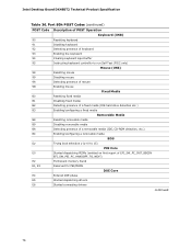
Intel Desktop Board DX48BT2 Technical Product Specification Table 36. Port 80h POST Codes (continued) POST Code Description of POST Operation Keyboard (USB) 90 Resetting keyboard 91 ... on first report of EFI_SW_PC_INIT_BEGIN EFI_SW_PEI_PC_HANDOFF_TO_NEXT) E2 Permanent memory found E1, E3 Reserved for PEI/PEIMs DXE Core E4 Entered DXE phase E5 Started dispatching drivers E6 Started connecting drivers continued 76
Intel Desktop Board DX48BT2 Technical Product Specification Table 36. Port 80h POST Codes (continued) POST Code Description of POST Operation Keyboard (USB) 90 Resetting keyboard 91 ... on first report of EFI_SW_PC_INIT_BEGIN EFI_SW_PEI_PC_HANDOFF_TO_NEXT) E2 Permanent memory found E1, E3 Reserved for PEI/PEIMs DXE Core E4 Entered DXE phase E5 Started dispatching drivers E6 Started connecting drivers continued 76

Product Specification
Page 77
Error Messages and Beep Codes Table 36. Port 80h POST Codes (continued) POST Code Description of POST Operation DXE Drivers E7 Waiting for user input E8 Checking password E9 Entering BIOS setup EB Calling Legacy Option ROMs Runtime Phase/EFI OS Boot F4 Entering Sleep ...
Error Messages and Beep Codes Table 36. Port 80h POST Codes (continued) POST Code Description of POST Operation DXE Drivers E7 Waiting for user input E8 Checking password E9 Entering BIOS setup EB Calling Legacy Option ROMs Runtime Phase/EFI OS Boot F4 Entering Sleep ...


