
Product Specification
Page 7
...110 4.4.8 USB Configuration Submenu 111 4.4.9 Chipset Configuration Submenu 112 4.4.10 Fan Control Configuration Submenu 115 4.4.11 Hardware Monitoring 116 4.5 Security Menu ...117 4.6 Power Menu ...118 4.6.1 ACPI Submenu 118 4.7 Boot Menu ...119 4.7.1 Boot Device Priority Submenu 120 4.7.2 Hard Disk Drives Submenu 121 4.7.3 Removable Devices Submenu 121 4.7.4 ATAPI CD-ROM Drives Submenu 122 4.8 Exit Menu ...122 5 Error Messages and Beep Codes 5.1 BIOS Error Messages 123 5.2 Port 80h POST Codes 125 5.3 Bus Initialization Checkpoints 129 5.4 Speaker ...130 5.5 BIOS Beep Codes ...130...
...110 4.4.8 USB Configuration Submenu 111 4.4.9 Chipset Configuration Submenu 112 4.4.10 Fan Control Configuration Submenu 115 4.4.11 Hardware Monitoring 116 4.5 Security Menu ...117 4.6 Power Menu ...118 4.6.1 ACPI Submenu 118 4.7 Boot Menu ...119 4.7.1 Boot Device Priority Submenu 120 4.7.2 Hard Disk Drives Submenu 121 4.7.3 Removable Devices Submenu 121 4.7.4 ATAPI CD-ROM Drives Submenu 122 4.8 Exit Menu ...122 5 Error Messages and Beep Codes 5.1 BIOS Error Messages 123 5.2 Port 80h POST Codes 125 5.3 Bus Initialization Checkpoints 129 5.4 Speaker ...130 5.5 BIOS Beep Codes ...130...
Product Specification
Page 8
...the Power Switch 46 15. Location of the Jumper Blocks 74 22. Connection Diagram for Analog CRTs 28 9. Video BIOS Video Modes Supported for Front Panel USB Connectors 73 21. LAN Connector LED Locations 42 12. Direct Draw Supported Modes 27 8. Back Panel Audio Connector Options for S/PDIF Back Panel Connector 40 9. Thermal Monitoring...44 13. Power and Hardware Control Connectors 65 17. External I /O Shield Dimensions 77 24. Desktop Board D865GVHZ Dimensions 76 23. Characteristics of Single Channel Configuration with Dynamic Mode 24 6. Specifications...
...the Power Switch 46 15. Location of the Jumper Blocks 74 22. Connection Diagram for Analog CRTs 28 9. Video BIOS Video Modes Supported for Front Panel USB Connectors 73 21. LAN Connector LED Locations 42 12. Direct Draw Supported Modes 27 8. Back Panel Audio Connector Options for S/PDIF Back Panel Connector 40 9. Thermal Monitoring...44 13. Power and Hardware Control Connectors 65 17. External I /O Shield Dimensions 77 24. Desktop Board D865GVHZ Dimensions 76 23. Characteristics of Single Channel Configuration with Dynamic Mode 24 6. Specifications...

Product Specification
Page 13
... Intel® 82562EZ Platform LAN Connect (PLC) device For information about The board's compliance level with ACPI, Plug and Play, and SMBIOS Refer to use the same LED as the onboard IDE controller. Not every manufacturing option is available in hard drive controllers (SCSI or other) to Section 1.4, page 17 1.1.2 Manufacturing Options Table 2 describes the manufacturing options on PCI, RS-232, front panel, PS/2 devices, and USB ports Expansion Capabilities Three PCI bus add-in card connectors...
... Intel® 82562EZ Platform LAN Connect (PLC) device For information about The board's compliance level with ACPI, Plug and Play, and SMBIOS Refer to use the same LED as the onboard IDE controller. Not every manufacturing option is available in hard drive controllers (SCSI or other) to Section 1.4, page 17 1.1.2 Manufacturing Options Table 2 describes the manufacturing options on PCI, RS-232, front panel, PS/2 devices, and USB ports Expansion Capabilities Three PCI bus add-in card connectors...
Product Specification
Page 17
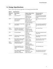
Product Description 1.4 Design Specifications Table 3 lists the specifications applicable to the Desktop Board D865GVHZ. Version 1.0b, February 08, 1999, Intel Corporation, Microsoft Corporation, and Toshiba Corporation. The information is available from... Specifications Reference Name AC '97 ACPI ASF ATA/ ATAPI-5 ATX Specification Title Audio Codec '97 Advanced Configuration and Power Interface Specification Alert Standard Format (ASF) Specification Information Technology-AT Attachment with Packet Interface - 5 (ATA/ATAPI-5) ATX Specification Version, Revision Date...
Product Description 1.4 Design Specifications Table 3 lists the specifications applicable to the Desktop Board D865GVHZ. Version 1.0b, February 08, 1999, Intel Corporation, Microsoft Corporation, and Toshiba Corporation. The information is available from... Specifications Reference Name AC '97 ACPI ASF ATA/ ATAPI-5 ATX Specification Title Audio Codec '97 Advanced Configuration and Power Interface Specification Alert Standard Format (ASF) Specification Information Technology-AT Attachment with Packet Interface - 5 (ATA/ATAPI-5) ATX Specification Version, Revision Date...
Product Specification
Page 36
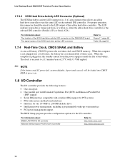
... • PCI power management support The BIOS Setup program provides configuration options for the I /O Controller Refer to Figure 17, page 68 Table 35, page 69 1.7.4 Real-Time Clock, CMOS SRAM, and Battery A coin-cell battery (CR2032) powers the real-time clock and CMOS memory. Intel Desktop Board D865GVHZ Technical Product Specification 1.7.3.3 SCSI Hard Drive Activity LED Connector (Optional) The SCSI hard drive activity LED connector is a 1 x 2-pin connector that allows an add-in hard drive controller to the LED output of the add-in hard drive controller. For...
... • PCI power management support The BIOS Setup program provides configuration options for the I /O Controller Refer to Figure 17, page 68 Table 35, page 69 1.7.4 Real-Time Clock, CMOS SRAM, and Battery A coin-cell battery (CR2032) powers the real-time clock and CMOS memory. Intel Desktop Board D865GVHZ Technical Product Specification 1.7.3.3 SCSI Hard Drive Activity LED Connector (Optional) The SCSI hard drive activity LED connector is a 1 x 2-pin connector that allows an add-in hard drive controller to the LED output of the add-in hard drive controller. For...
Product Specification
Page 60
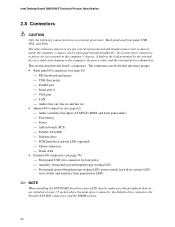
... panel I/O connectors (see page 61) PS/2 keyboard and mouse USB (four ports) Parallel port Serial port A VGA port LAN Audio (line out, line in, and mic in) • Internal I/O connectors (see page 62) Audio (auxiliary line input, ATAPI CD-ROM, and front panel audio) Fans [three] Power Add-in boards (PCI) Parallel ATA IDE Diskette drive SCSI hard drive activity LED (optional) Chassis intrusion...
... panel I/O connectors (see page 61) PS/2 keyboard and mouse USB (four ports) Parallel port Serial port A VGA port LAN Audio (line out, line in, and mic in) • Internal I/O connectors (see page 62) Audio (auxiliary line input, ATAPI CD-ROM, and front panel audio) Fans [three] Power Add-in boards (PCI) Parallel ATA IDE Diskette drive SCSI hard drive activity LED (optional) Chassis intrusion...
Product Specification
Page 68
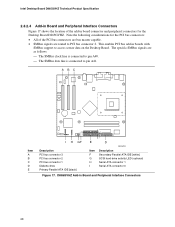
... ATA IDE [white] SCSI hard drive activity LED (optional) Serial ATA connector 1 Serial ATA connector 0 Figure 17. This enables PCI bus add-in boards with SMBus support to pin A41. The specific SMBus signals are routed to PCI bus connector 2. Intel Desktop Board D865GVHZ Technical Product Specification 2.8.2.4 Add-in Board and Peripheral Interface Connectors Figure 17 shows the location of the PCI bus connectors are bus master capable. • SMBus signals are as follows: The SMBus clock line is connected to pin...
... ATA IDE [white] SCSI hard drive activity LED (optional) Serial ATA connector 1 Serial ATA connector 0 Figure 17. This enables PCI bus add-in boards with SMBus support to pin A41. The specific SMBus signals are routed to PCI bus connector 2. Intel Desktop Board D865GVHZ Technical Product Specification 2.8.2.4 Add-in Board and Peripheral Interface Connectors Figure 17 shows the location of the PCI bus connectors are bus master capable. • SMBus signals are as follows: The SMBus clock line is connected to pin...
Product Specification
Page 88
... ATA-66/100 compatible cable • ATA-66/100 operating system device drivers ✏ NOTE Do not connect an ATA device as a slave on the system after adding a PCI card, the BIOS automatically configures interrupts, the I /O channel support. The IDE interface supports hard drives up to ATA-66/100 and recognizes any ATAPI compliant devices, including CD-ROM drives, tape drives, and Ultra DMA drives (see Section 1.4 for use ATA-66/100...
... ATA-66/100 compatible cable • ATA-66/100 operating system device drivers ✏ NOTE Do not connect an ATA device as a slave on the system after adding a PCI card, the BIOS automatically configures interrupts, the I /O channel support. The IDE interface supports hard drives up to ATA-66/100 and recognizes any ATAPI compliant devices, including CD-ROM drives, tape drives, and Ultra DMA drives (see Section 1.4 for use ATA-66/100...
Product Specification
Page 91
... Section 1.2, page 16 91 BIOS upgrades and the Intel Flash Memory Update Utility are available from Intel Customer Support through the Intel World Wide Web site. ✏ NOTE Even if the computer is configured to boot from an LS-120 diskette (in the Setup program's Removable Devices submenu), the BIOS recovery diskette must be programmed into the flash memory using the BIOS recovery mode. For information about The Intel World Wide Web site Refer...
... Section 1.2, page 16 91 BIOS upgrades and the Intel Flash Memory Update Utility are available from Intel Customer Support through the Intel World Wide Web site. ✏ NOTE Even if the computer is configured to boot from an LS-120 diskette (in the Setup program's Removable Devices submenu), the BIOS recovery diskette must be programmed into the flash memory using the BIOS recovery mode. For information about The Intel World Wide Web site Refer...
Product Specification
Page 95
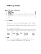
.... BIOS Setup Program Menu Bar Maintenance Main Advanced Security Clears passwords and displays processor information Displays processor and memory configuration Configures advanced features available through the chipset Sets passwords and security features Power Boot Configures power management features and power supply controls Selects boot options Exit Saves or discards changes to view and change the BIOS settings for the computer. Table 52. Section 2.9.2 on page 75 tells how to put the Desktop Board in configure mode. The menu bar is accessed by pressing the key...
.... BIOS Setup Program Menu Bar Maintenance Main Advanced Security Clears passwords and displays processor information Displays processor and memory configuration Configures advanced features available through the chipset Sets passwords and security features Power Boot Configures power management features and power supply controls Selects boot options Exit Saves or discards changes to view and change the BIOS settings for the computer. Table 52. Section 2.9.2 on page 75 tells how to put the Desktop Board in configure mode. The menu bar is accessed by pressing the key...
Product Specification
Page 96
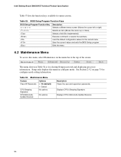
... default configuration values for clearing Setup passwords and displaying processor information. Setup only displays this menu, select Maintenance on page 75 for menu screens. Maintenance Main Advanced Security Power Boot Exit The menu shown in Table 54 is for the current menu Save the current values and exits the BIOS Setup program Exits the menu 4.2 Maintenance Menu To access this menu in configure mode. Maintenance Menu Feature Options Clear All Passwords • Ok (default) • Cancel CPU Stepping Signature No options CPU Microcode Update...
... default configuration values for clearing Setup passwords and displaying processor information. Setup only displays this menu, select Maintenance on page 75 for menu screens. Maintenance Main Advanced Security Power Boot Exit The menu shown in Table 54 is for the current menu Save the current values and exits the BIOS Setup program Exits the menu 4.2 Maintenance Menu To access this menu in configure mode. Maintenance Menu Feature Options Clear All Passwords • Ok (default) • Cancel CPU Stepping Signature No options CPU Microcode Update...
Product Specification
Page 103
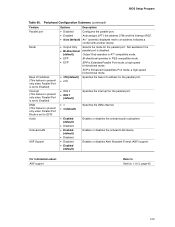
... (This feature is present only when Parallel Port is set to Enabled) Interrupt (This feature is present only when Parallel Port is set to ECP) Audio Onboard LAN ASF Support Options Description • Disabled Configures the parallel port. • Enabled Auto assigns LPT1 the address 378h and the interrupt IRQ7. • Auto (default) An * (asterisk) displayed next to Section 1.10.3, page 43 103 Enables or disables the onboard LAN device. BIOS Setup Program Table 60.
... (This feature is present only when Parallel Port is set to Enabled) Interrupt (This feature is present only when Parallel Port is set to ECP) Audio Onboard LAN ASF Support Options Description • Disabled Configures the parallel port. • Enabled Auto assigns LPT1 the address 378h and the interrupt IRQ7. • Auto (default) An * (asterisk) displayed next to Section 1.10.3, page 43 103 Enables or disables the onboard LAN device. BIOS Setup Program Table 60.
Product Specification
Page 107
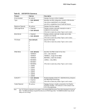
Specifies the IDE configuration mode for the drive. Auto = Auto-detected SWDMAn = Single Word DMAn MWDMAn = Multi Word DMAn UDMAn = Ultra DMAn (This item is read-only unless Type is set to User.) Enables/disables S.M.A.R.T. (Self-Monitoring, Analysis, and Reporting Technology). (This item is read -only unless Type is set to User.) Displays the type of drive installed. Cable Detected Options No options • Auto (default) • User No options • Disabled • Auto (default) • Disabled • Auto (default) Auto (default) 0 1 2 3 4 • Auto (default) • ...
Specifies the IDE configuration mode for the drive. Auto = Auto-detected SWDMAn = Single Word DMAn MWDMAn = Multi Word DMAn UDMAn = Ultra DMAn (This item is read-only unless Type is set to User.) Enables/disables S.M.A.R.T. (Self-Monitoring, Analysis, and Reporting Technology). (This item is read -only unless Type is set to User.) Displays the type of drive installed. Cable Detected Options No options • Auto (default) • User No options • Disabled • Auto (default) • Disabled • Auto (default) Auto (default) 0 1 2 3 4 • Auto (default) • ...

Product Specification
Page 113
... Configuration is displayed only if the installed processor has a 533 MHz system bus. 3. User Defined • 8 • 7 (default) • 6 • 5 • 2.0 • 2.5 (default) • 3.0 • 4 • 3 (default) • 2 • 4 • 3 (default) • 2 Description Controls the CPC/1n rule mode. Aggressive = Selects most aggressive user-defined timings. This option is set to the memory detected. User Defined. 113 Corresponds to CAS# Delay (Note 4) SDRAM RAS# Precharge (Note 4) Options • Auto (default...
... Configuration is displayed only if the installed processor has a 533 MHz system bus. 3. User Defined • 8 • 7 (default) • 6 • 5 • 2.0 • 2.5 (default) • 3.0 • 4 • 3 (default) • 2 • 4 • 3 (default) • 2 Description Controls the CPC/1n rule mode. Aggressive = Selects most aggressive user-defined timings. This option is set to the memory detected. User Defined. 113 Corresponds to CAS# Delay (Note 4) SDRAM RAS# Precharge (Note 4) Options • Auto (default...
Product Specification
Page 115
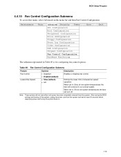
... BIOS Setup Program 4.4.10 Fan Control Configuration Submenu To access this menu, select Advanced on . 115 Fan Control Configuration Submenu Feature Fan Control Lowest Fan Speed Options • Disabled • Enabled (default) • Slow (default) • Off Description Enables or disables fan control. Maintenance Main Advanced Security Power PCI Configuration Boot Configuration Peripheral Configuration Drive Configuration Floppy Configuration Event Log Configuration Video Configuration USB Configuration Chipset Configuration Fan Control Configuration Hardware Monitoring Boot...
... BIOS Setup Program 4.4.10 Fan Control Configuration Submenu To access this menu, select Advanced on . 115 Fan Control Configuration Submenu Feature Fan Control Lowest Fan Speed Options • Disabled • Enabled (default) • Slow (default) • Off Description Enables or disables fan control. Maintenance Main Advanced Security Power PCI Configuration Boot Configuration Peripheral Configuration Drive Configuration Floppy Configuration Event Log Configuration Video Configuration USB Configuration Chipset Configuration Fan Control Configuration Hardware Monitoring Boot...
Product Specification
Page 119
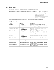
... LAN. Maintenance Main Advanced Security Power Boot Exit Boot Device Priority Hard Disk Drives Removable Devices ATAPI CD-ROM Drives The menu represented in Table 74 is used to be available in the Boot Device menu. Enabled displays OEM graphic instead of boot devices. Note: When set to Enabled, you must reboot for the Intel Boot Agent device to set the boot features and the boot sequence. Specifies the boot sequence from the menu bar at the top of the screen. BIOS Setup Program 4.7 Boot Menu To access this menu...
... LAN. Maintenance Main Advanced Security Power Boot Exit Boot Device Priority Hard Disk Drives Removable Devices ATAPI CD-ROM Drives The menu represented in Table 74 is used to be available in the Boot Device menu. Enabled displays OEM graphic instead of boot devices. Note: When set to Enabled, you must reboot for the Intel Boot Agent device to set the boot features and the boot sequence. Specifies the boot sequence from the menu bar at the top of the screen. BIOS Setup Program 4.7 Boot Menu To access this menu...
Product Specification
Page 120
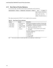
Intel Desktop Board D865GVHZ Technical Product Specification 4.7.1 Boot Device Priority Submenu To access this menu, select Boot on the BIOS release. 120 Only one of the devices can be an IDE hard disk drive. To specify boot sequence: 1. The computer will attempt to boot from up to the device type. Table 75. The default settings for the first through fourth boot devices are, respectively: • Removable Dev. • Hard Drive • ATAPI CD-ROM • Intel Boot Agent Note: The...
Intel Desktop Board D865GVHZ Technical Product Specification 4.7.1 Boot Device Priority Submenu To access this menu, select Boot on the BIOS release. 120 Only one of the devices can be an IDE hard disk drive. To specify boot sequence: 1. The computer will attempt to boot from up to the device type. Table 75. The default settings for the first through fourth boot devices are, respectively: • Removable Dev. • Hard Drive • ATAPI CD-ROM • Intel Boot Agent Note: The...
Product Specification
Page 125
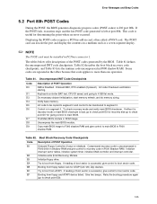
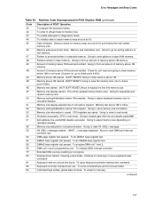
Displaying the POST-codes requires a PCI bus add-in ROM image. Keyboard controller BAT test, CPU ID saved, and going to check point E9). 125 Do necessary chipset initialization, start memory refresh, and do memory sizing. Find Main BIOS module in card, often called a POST card. Compressed recovery code is initialized. Retry the booting procedure again (go to check point D7 for ATAPI (LS-120, Zip) devices. Error Messages and Beep Codes 5.2 Port 80h POST Codes During the POST, the BIOS generates...
Displaying the POST-codes requires a PCI bus add-in ROM image. Keyboard controller BAT test, CPU ID saved, and going to check point E9). 125 Do necessary chipset initialization, start memory refresh, and do memory sizing. Find Main BIOS module in card, often called a POST card. Compressed recovery code is initialized. Retry the booting procedure again (go to check point D7 for ATAPI (LS-120, Zip) devices. Error Messages and Beep Codes 5.2 Port 80h POST Codes During the POST, the BIOS generates...
Product Specification
Page 127
.... 81 Keyboard reset error/stuck key found. To check for diagnostics mode. Memory test above 1M to follow. 52 Memory testing/initialization above 1M cleared. (SOFT RESET) Going to save memory size information. 53 Memory size information is in real mode. To program DMA unit 1 and 2. 66 DMA unit 1 and 2 programming over . To enable interrupts for lock-key. Memory size calculation over. Pattern to display the first 64k memory size. 4F Memory size display started...
.... 81 Keyboard reset error/stuck key found. To check for diagnostics mode. Memory test above 1M to follow. 52 Memory testing/initialization above 1M cleared. (SOFT RESET) Going to save memory size information. 53 Memory size information is in real mode. To program DMA unit 1 and 2. 66 DMA unit 1 and 2 programming over . To enable interrupts for lock-key. Memory size calculation over. Pattern to display the first 64k memory size. 4F Memory size display started...

Product Specification
Page 130
... a beep code (one long tone followed by two short tones) during POST if the video configuration fails (a faulty video card or no card installed) or if an external ROM module does not properly checksum to zero. Before shutting down the system if they fail. For information about The location of the onboard speaker on the Desktop Board D865GVHZ Refer to Figure 1, on page 14 5.5 BIOS Beep Codes Whenever a recoverable error occurs...
... a beep code (one long tone followed by two short tones) during POST if the video configuration fails (a faulty video card or no card installed) or if an external ROM module does not properly checksum to zero. Before shutting down the system if they fail. For information about The location of the onboard speaker on the Desktop Board D865GVHZ Refer to Figure 1, on page 14 5.5 BIOS Beep Codes Whenever a recoverable error occurs...


