
Product Specification
Page 6
... BIOS Flash Memory Organization 66 3.3 Resource Configuration 66 3.3.1 PCI Autoconfiguration 66 3.3.2 PCI IDE Support 66 3.4 System Management BIOS (SMBIOS 67 3.5 Legacy USB Support...67 3.6 BIOS Updates ...68 3.6.1 Language Support 68 3.6.2 Custom Splash Screen 68 3.7 Boot Options ...69 3.7.1 CD-ROM Boot 69 3.7.2 Network Boot 69 3.7.3 Booting Without Attached Devices 69 3.7.4 Changing the Default Boot Device During POST 69 3.8 Fast Booting Systems with Intel® Rapid BIOS Boot 70 3.8.1 Peripheral Selection and Configuration 70 3.8.2 Intel Rapid BIOS Boot 70 3.9 BIOS Security...
... BIOS Flash Memory Organization 66 3.3 Resource Configuration 66 3.3.1 PCI Autoconfiguration 66 3.3.2 PCI IDE Support 66 3.4 System Management BIOS (SMBIOS 67 3.5 Legacy USB Support...67 3.6 BIOS Updates ...68 3.6.1 Language Support 68 3.6.2 Custom Splash Screen 68 3.7 Boot Options ...69 3.7.1 CD-ROM Boot 69 3.7.2 Network Boot 69 3.7.3 Booting Without Attached Devices 69 3.7.4 Changing the Default Boot Device During POST 69 3.8 Fast Booting Systems with Intel® Rapid BIOS Boot 70 3.8.1 Peripheral Selection and Configuration 70 3.8.2 Intel Rapid BIOS Boot 70 3.9 BIOS Security...
Product Specification
Page 7
... 17. Connection Diagram for Front Panel USB Connectors 50 15. Board Dimensions...53 18. Feature Summary ...10 2. LAN Connector LED States 26 6. High Definition Audio Subsystem Block Diagram 25 8. Connection Diagram for Front Panel Connector 49 14. Back Panel Connectors 42 12. System Memory Map 37 10. Interrupts ...40 14. PCI Configuration Space Map 39 13. Contents 4 Error Messages and Beep Codes 4.1 BIOS Error Messages 73 4.2 Port 80h POST Codes 75 4.3 Bus Initialization Checkpoints 79 4.4 Speaker ...80 4.5 BIOS Beep Codes...80 Figures 1. Block Diagram...14...
... 17. Connection Diagram for Front Panel USB Connectors 50 15. Board Dimensions...53 18. Feature Summary ...10 2. LAN Connector LED States 26 6. High Definition Audio Subsystem Block Diagram 25 8. Connection Diagram for Front Panel Connector 49 14. Back Panel Connectors 42 12. System Memory Map 37 10. Interrupts ...40 14. PCI Configuration Space Map 39 13. Contents 4 Error Messages and Beep Codes 4.1 BIOS Error Messages 73 4.2 Port 80h POST Codes 75 4.3 Bus Initialization Checkpoints 79 4.4 Speaker ...80 4.5 BIOS Beep Codes...80 Figures 1. Block Diagram...14...

Product Specification
Page 8
... and User Password Functions 71 40. BIOS Error Messages 73 41. Fan Connector Current Capability 55 31. BIOS Setup Program Menu Bar 66 37. Upper Nibble High Byte Functions 79 46. Intel Desktop Board D910GLDW Technical Product Specification 18. Product Certification Markings 64 36. Uncompressed INIT Code Checkpoints 75 42. Lower Nibble High Byte Functions 80 47. Front Chassis Fan and Rear Chassis Fan Connectors 46 19. BIOS Setup Configuration Jumper Settings 52 29. Boot Device Menu Options 69 39. Processor Fan Connector...
... and User Password Functions 71 40. BIOS Error Messages 73 41. Fan Connector Current Capability 55 31. BIOS Setup Program Menu Bar 66 37. Upper Nibble High Byte Functions 79 46. Intel Desktop Board D910GLDW Technical Product Specification 18. Product Certification Markings 64 36. Uncompressed INIT Code Checkpoints 75 42. Lower Nibble High Byte Functions 80 47. Front Chassis Fan and Rear Chassis Fan Connectors 46 19. BIOS Setup Configuration Jumper Settings 52 29. Boot Device Menu Options 69 39. Processor Fan Connector...
Product Specification
Page 9
... 1.1 PCI Bus Terminology Change 9 1.2 Overview ...10 1.3 Online Support ...15 1.4 Processor ...15 1.5 System Memory ...15 1.6 Intel® 910GL Chipset 19 1.7 PCI Express Connector 22 1.8 I/O Controller...23 1.9 Audio Subsystem ...24 1.10 LAN Subsystem (Optional 26 1.11 Hardware Management Subsystem 28 1.12 Power Management ...30 1.1 PCI Bus Terminology Change Previous generations of Intel Desktop Boards adds a new technology for add-in card connector referred to as PCI. This generation of Intel® Desktop Boards used an add-in cards: PCI Express*. The 32-bit parallel bus...
... 1.1 PCI Bus Terminology Change 9 1.2 Overview ...10 1.3 Online Support ...15 1.4 Processor ...15 1.5 System Memory ...15 1.6 Intel® 910GL Chipset 19 1.7 PCI Express Connector 22 1.8 I/O Controller...23 1.9 Audio Subsystem ...24 1.10 LAN Subsystem (Optional 26 1.11 Hardware Management Subsystem 28 1.12 Power Management ...30 1.1 PCI Bus Terminology Change Previous generations of Intel Desktop Boards adds a new technology for add-in card connector referred to as PCI. This generation of Intel® Desktop Boards used an add-in cards: PCI Express*. The 32-bit parallel bus...
Product Specification
Page 10
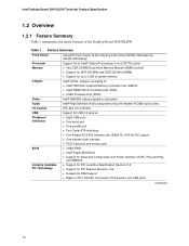
... Parallel ATA IDE interface with UDMA 33, ATA-66/100 support • One diskette drive interface • PS/2* keyboard and mouse ports • 4 Mbit FWH • Intel® Rapid BIOS Boot • Support for Advanced Configuration and Power Interface (ACPI), Plug and Play, and SMBIOS • Support for PCI Local Bus Specification Revision 2.2 • Support for up to RAM support • Wake on PCI, RS-232, front panel, PS/2 devices, and USB ports continued 10 Table...
... Parallel ATA IDE interface with UDMA 33, ATA-66/100 support • One diskette drive interface • PS/2* keyboard and mouse ports • 4 Mbit FWH • Intel® Rapid BIOS Boot • Support for Advanced Configuration and Power Interface (ACPI), Plug and Play, and SMBIOS • Support for PCI Local Bus Specification Revision 2.2 • Support for up to RAM support • Wake on PCI, RS-232, front panel, PS/2 devices, and USB ports continued 10 Table...
Product Specification
Page 13
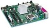
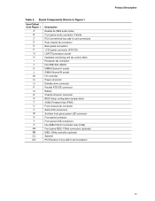
... monitoring and fan control ASIC Processor fan connector Intel 82910GL GMCH DIMM Channel A socket DIMM Channel B socket I/O controller Power connector Diskette drive connector Parallel ATE IDE connector Battery Chassis intrusion connector BIOS Setup configuration jumper block 4 Mbit Firmware Hub (FWH) Front chassis fan connector Serial ATA connectors Auxiliary front panel power LED connector Front panel connector Front panel USB connectors Intel 82801FB I/O Controller Hub (ICH6) Front panel IEEE-1394a connectors (optional) IEEE-1394a controller (optional) Speaker PCI Express x1 bus add-in card...
... monitoring and fan control ASIC Processor fan connector Intel 82910GL GMCH DIMM Channel A socket DIMM Channel B socket I/O controller Power connector Diskette drive connector Parallel ATE IDE connector Battery Chassis intrusion connector BIOS Setup configuration jumper block 4 Mbit Firmware Hub (FWH) Front chassis fan connector Serial ATA connectors Auxiliary front panel power LED connector Front panel connector Front panel USB connectors Intel 82801FB I/O Controller Hub (ICH6) Front panel IEEE-1394a connectors (optional) IEEE-1394a controller (optional) Speaker PCI Express x1 bus add-in card...
Product Specification
Page 14
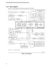
... block diagram of the major functional areas of the board. PCI Express x1 Slot 1 PCI Express x1 Interface Parallel ATA IDE Connector LGA775 Processor Socket Parallel ATA IDE Interface System Bus (533 MHz) USB Back Panel/Front Panel USB Ports LPC Bus I/O Controller LPC Bus Serial Ports Parallel Port PS/2 Mouse PS/2 Keyboard Diskette Drive Connector DMI Interconnect High Definition Audio Link LAN Connect Interface Intel 82910GL Graphics and Memory Controller Hub (GMCH) VGA Port Channel A DIMM Display Interface Dual-Channel Memory Bus SMBus Channel B DIMM Intel 82801FB I/O Controller...
... block diagram of the major functional areas of the board. PCI Express x1 Slot 1 PCI Express x1 Interface Parallel ATA IDE Connector LGA775 Processor Socket Parallel ATA IDE Interface System Bus (533 MHz) USB Back Panel/Front Panel USB Ports LPC Bus I/O Controller LPC Bus Serial Ports Parallel Port PS/2 Mouse PS/2 Keyboard Diskette Drive Connector DMI Interconnect High Definition Audio Link LAN Connect Interface Intel 82910GL Graphics and Memory Controller Hub (GMCH) VGA Port Channel A DIMM Display Interface Dual-Channel Memory Bus SMBus Channel B DIMM Intel 82801FB I/O Controller...

Product Specification
Page 20
... system memory is installed. Intel Desktop Board D910GLDW Technical Product Specification 1.6.1.1 Dynamic Video Memory Technology (DVMT) DVMT enables enhanced graphics and memory performance through Direct AGP, and highly efficient memory utilization. DVMT returns system memory back to eight USB 2.0 ports, supports UHCI and EHCI, and uses UHCI- The port arrangement is as set in the BIOS Setup program) for all ports. DVMT will always use of system physical memory (as follows: • Four ports are implemented with legacy applications...
... system memory is installed. Intel Desktop Board D910GLDW Technical Product Specification 1.6.1.1 Dynamic Video Memory Technology (DVMT) DVMT enables enhanced graphics and memory performance through Direct AGP, and highly efficient memory utilization. DVMT returns system memory back to eight USB 2.0 ports, supports UHCI and EHCI, and uses UHCI- The port arrangement is as set in the BIOS Setup program) for all ports. DVMT will always use of system physical memory (as follows: • Four ports are implemented with legacy applications...

Product Specification
Page 21
... a boot device by setting the BIOS Setup program's Boot menu to device connections, unlike Parallel ATA IDE which supports a master/slave configuration and two devices per port. The board supports Laser Servo (LS-120) diskette technology through the Parallel ATA IDE interfaces. An LS-120 drive can achieve read transfer rates up to 100 MB/sec and write transfer rates up to 66 MB/sec. floppy disk drive) • ARMD-HDD (ATAPI removable media device...
... a boot device by setting the BIOS Setup program's Boot menu to device connections, unlike Parallel ATA IDE which supports a master/slave configuration and two devices per port. The board supports Laser Servo (LS-120) diskette technology through the Parallel ATA IDE interfaces. An LS-120 drive can achieve read transfer rates up to 100 MB/sec and write transfer rates up to 66 MB/sec. floppy disk drive) • ARMD-HDD (ATAPI removable media device...
Product Specification
Page 42
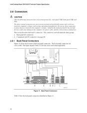
... and should connect only to devices inside the computer's chassis, such as fans and internal peripherals. Intel Desktop Board D910GLDW Technical Product Specification 2.8 Connectors CAUTION Only the following connectors have overcurrent protection: back panel USB, front panel USB, and PS/2. Back Panel Connectors OM17314 Table 15 lists the back panel connectors identified in the load presented by the external devices could cause damage to the computer's chassis. The other internal connectors are color-coded. The figure...
... and should connect only to devices inside the computer's chassis, such as fans and internal peripherals. Intel Desktop Board D910GLDW Technical Product Specification 2.8 Connectors CAUTION Only the following connectors have overcurrent protection: back panel USB, front panel USB, and PS/2. Back Panel Connectors OM17314 Table 15 lists the back panel connectors identified in the load presented by the external devices could cause damage to the computer's chassis. The other internal connectors are color-coded. The figure...
Product Specification
Page 65
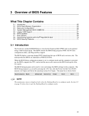
... Contains 3.1 Introduction ...65 3.2 BIOS Flash Memory Organization 66 3.3 Resource Configuration 66 3.4 System Management BIOS (SMBIOS 67 3.5 Legacy USB Support...67 3.6 BIOS Updates ...68 3.7 Boot Options ...69 3.8 Fast Booting Systems with Intel® Rapid BIOS Boot 70 3.9 BIOS Security Features 71 3.1 Introduction The board uses an Intel/AMI BIOS that is stored in configure mode. The BIOS Setup program is shown below. The menu bar is accessed by pressing the key after the Power-On Self-Test (POST) memory test begins and...
... Contains 3.1 Introduction ...65 3.2 BIOS Flash Memory Organization 66 3.3 Resource Configuration 66 3.4 System Management BIOS (SMBIOS 67 3.5 Legacy USB Support...67 3.6 BIOS Updates ...68 3.7 Boot Options ...69 3.8 Fast Booting Systems with Intel® Rapid BIOS Boot 70 3.9 BIOS Security Features 71 3.1 Introduction The board uses an Intel/AMI BIOS that is stored in configure mode. The BIOS Setup program is shown below. The menu bar is accessed by pressing the key after the Power-On Self-Test (POST) memory test begins and...
Product Specification
Page 66
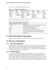
...the menu 3.2 BIOS Flash Memory Organization The Firmware Hub (FWH) includes a 4 Mbit (512 KB) symmetrical flash memory device. 3.3 Resource Configuration 3.3.1 PCI Autoconfiguration The BIOS can automatically configure PCI devices. Autoconfiguration lets a user insert or remove PCI cards without having to Setup program options Table 37 lists the function keys available for Logical Block Addressing (LBA) and 66 Table 36. When a user turns on the system after adding a PCI card, the BIOS automatically configures interrupts, the I /O channel support. Intel Desktop Board D910GLDW...
...the menu 3.2 BIOS Flash Memory Organization The Firmware Hub (FWH) includes a 4 Mbit (512 KB) symmetrical flash memory device. 3.3 Resource Configuration 3.3.1 PCI Autoconfiguration The BIOS can automatically configure PCI devices. Autoconfiguration lets a user insert or remove PCI cards without having to Setup program options Table 37 lists the function keys available for Logical Block Addressing (LBA) and 66 Table 36. When a user turns on the system after adding a PCI card, the BIOS automatically configures interrupts, the I /O channel support. Intel Desktop Board D910GLDW...
Product Specification
Page 67
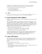
... compatible cable • ATA-66/100 operating system device drivers NOTE Do not connect an ATA device as a slave on the same IDE cable as Windows NT*, require an additional interface for obtaining the SMBIOS information. The main component of the drive. POST begins. 3. Legacy USB support is enabled by specifying manual configuration in a managed network. You can obtain the SMBIOS information. 3.5 Legacy USB Support Legacy USB support enables USB devices to be used to access the BIOS Setup program, and to install...
... compatible cable • ATA-66/100 operating system device drivers NOTE Do not connect an ATA device as a slave on the same IDE cable as Windows NT*, require an additional interface for obtaining the SMBIOS information. The main component of the drive. POST begins. 3. Legacy USB support is enabled by specifying manual configuration in a managed network. You can obtain the SMBIOS information. 3.5 Legacy USB Support Legacy USB support enables USB devices to be used to access the BIOS Setup program, and to install...
Product Specification
Page 69
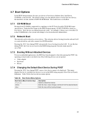
... POST Pressing the key during POST, the User Access Level in the BIOS Setup program's Security menu must be set in the BIOS Setup program, ATAPI CD-ROM is invoked even if the following devices are defined in compliance to boot from a diskette drive, hard drives, CD-ROM, or the network. Table 38. Accordingly, if there is not a bootable CD in card with a remote boot ROM installed. Table 38 lists the boot device menu options. The fourth device is supported...
... POST Pressing the key during POST, the User Access Level in the BIOS Setup program's Security menu must be set in the BIOS Setup program, ATAPI CD-ROM is invoked even if the following devices are defined in compliance to boot from a diskette drive, hard drives, CD-ROM, or the network. Table 38. Accordingly, if there is not a bootable CD in card with a remote boot ROM installed. Table 38 lists the boot device menu options. The fourth device is supported...

Product Specification
Page 70
... a programmable delay ranging from the POST execution time. • Disable Quiet Boot, which enables the system to data ready" less than eight seconds, that the Intel logo screen (or a custom logo splash screen) will not be initialized at all. In the Boot Menu: • Set the hard disk drive as logo displays, screen repaints, or mode changes in the Drive Configuration Submenu of option ROM boot time. This rate can reduce up...
... a programmable delay ranging from the POST execution time. • Disable Quiet Boot, which enables the system to data ready" less than eight seconds, that the Intel logo screen (or a custom logo splash screen) will not be initialized at all. In the Boot Menu: • Set the hard disk drive as logo displays, screen repaints, or mode changes in the Drive Configuration Submenu of option ROM boot time. This rate can reduce up...
Product Specification
Page 74
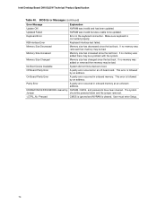
... error occurred in onboard memory. User must enter Setup. 74 Memory Size Increased Memory size has increased since the last boot. Memory Size Changed Memory size has changed since the last boot. This error is cleared. Keyboard Error Error in the keyboard connection. If no memory was removed then memory may be a problem with the system. If no memory was added there may be bad. The system Jumper should be updated. Make sure keyboard is followed by NVRAM, CMOS, and passwords have been cleared. KB/Interface Error Keyboard...
... error occurred in onboard memory. User must enter Setup. 74 Memory Size Increased Memory size has increased since the last boot. Memory Size Changed Memory size has changed since the last boot. This error is cleared. Keyboard Error Error in the keyboard connection. If no memory was removed then memory may be a problem with the system. If no memory was added there may be bad. The system Jumper should be updated. Make sure keyboard is followed by NVRAM, CMOS, and passwords have been cleared. KB/Interface Error Keyboard...
Product Specification
Page 75
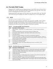
... boot sector code. Control is uncompressed in F000:0000 in Shadow RAM and give control to be installed in F000 Shadow RAM. Init code to be copied to segment 0 and control to main BIOS in F000 shadow RAM. Compressed recovery code is in card, often called a POST card. Try to main BIOS. Error Messages and Beep Codes 4.2 Port 80h POST Codes During the POST, the BIOS generates diagnostic progress codes (POST-codes) to 4 GB flat mode. Table 41. Initialize floppy drive. Retry the booting...
... boot sector code. Control is uncompressed in F000:0000 in Shadow RAM and give control to be installed in F000 Shadow RAM. Init code to be copied to segment 0 and control to main BIOS in F000 shadow RAM. Compressed recovery code is in card, often called a POST card. Try to main BIOS. Error Messages and Beep Codes 4.2 Port 80h POST Codes During the POST, the BIOS generates diagnostic progress codes (POST-codes) to 4 GB flat mode. Table 41. Initialize floppy drive. Retry the booting...

Product Specification
Page 76
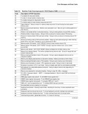
Intel Desktop Board D910GLDW Technical Product Specification Table 43. Going to look for details of POST Operation NMI is Disabled. About to disable DMA and Interrupt controllers. 13 Video display is disabled and port-B is pressed. Going to display the power-on message. 38 Different buses init (input, IPL, general devices) to start if present. (See Section 4.3 for the alternate display retrace checking. 34 Video display checking over. To display the...
Intel Desktop Board D910GLDW Technical Product Specification Table 43. Going to look for details of POST Operation NMI is Disabled. About to disable DMA and Interrupt controllers. 13 Video display is disabled and port-B is pressed. Going to display the power-on message. 38 Different buses init (input, IPL, general devices) to start if present. (See Section 4.3 for the alternate display retrace checking. 34 Video display checking over. To display the...
Product Specification
Page 77
... stuck key, to check for writing patterns to check point # 4Eh). Keyboard controller interface test over. Amount of memory below 1M cleared. (SOFT RESET) Going to be updated during memory test. continued 77 Error Messages and Beep Codes Table 43. Going to issue keyboard reset command. Pattern to clear memory above 1M complete. Memory below 1M memory. Memory size display adjusted due to relocation/ shadow. Shutdown successful, CPU in extended memory. message displayed...
... stuck key, to check for writing patterns to check point # 4Eh). Keyboard controller interface test over. Amount of memory below 1M cleared. (SOFT RESET) Going to be updated during memory test. continued 77 Error Messages and Beep Codes Table 43. Going to issue keyboard reset command. Pattern to clear memory above 1M complete. Memory below 1M memory. Memory size display adjusted due to relocation/ shadow. Shutdown successful, CPU in extended memory. message displayed...
Product Specification
Page 80
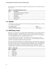
.... Table 46. The BIOS also issues a beep code (one long tone followed by two short tones) during POST if the video configuration fails (a faulty video card or no card installed) or if an external ROM module does not properly checksum to Figure 1, page 12 4.5 BIOS Beep Codes Whenever a recoverable error occurs during POST. For information about The location of the onboard speaker Refer to zero. Intel Desktop Board D910GLDW Technical Product Specification Table 46 describes...
.... Table 46. The BIOS also issues a beep code (one long tone followed by two short tones) during POST if the video configuration fails (a faulty video card or no card installed) or if an external ROM module does not properly checksum to Figure 1, page 12 4.5 BIOS Beep Codes Whenever a recoverable error occurs during POST. For information about The location of the onboard speaker Refer to zero. Intel Desktop Board D910GLDW Technical Product Specification Table 46 describes...


