
Product Specification
Page 5
... 1.2 Overview ...10 1.2.1 Feature Summary 10 1.2.2 Manufacturing Options 11 1.2.3 Board Layout 12 1.2.4 Block Diagram 14 1.3 Online Support ...15 1.4 Processor ...15 1.5 System Memory ...15 1.5.1 Memory Configurations 17 1.6 Intel® 910GL Chipset 19 1.6.1 Intel 910GL Graphics Controller 19 1.6.2 USB ...20 1.6.3 IDE Support 20 1.6.4 ... Monitoring and Fan Control ASIC 28 1.11.2 Thermal Monitoring 29 1.11.3 Fan Monitoring 30 1.11.4 Fan Speed Control (Intel® Precision Cooling Technology 30 1.11.5 Chassis Intrusion and Detection 30 1.12 Power Management ...30 1.12.1 ACPI ...31...
... 1.2 Overview ...10 1.2.1 Feature Summary 10 1.2.2 Manufacturing Options 11 1.2.3 Board Layout 12 1.2.4 Block Diagram 14 1.3 Online Support ...15 1.4 Processor ...15 1.5 System Memory ...15 1.5.1 Memory Configurations 17 1.6 Intel® 910GL Chipset 19 1.6.1 Intel 910GL Graphics Controller 19 1.6.2 USB ...20 1.6.3 IDE Support 20 1.6.4 ... Monitoring and Fan Control ASIC 28 1.11.2 Thermal Monitoring 29 1.11.3 Fan Monitoring 30 1.11.4 Fan Speed Control (Intel® Precision Cooling Technology 30 1.11.5 Chassis Intrusion and Detection 30 1.12 Power Management ...30 1.12.1 ACPI ...31...
Product Specification
Page 7
... 8. Front/Back Panel Audio Connector Options for Front Panel Connector 49 14. Component-side Connectors 44 13. I /O Map ...38 11. Board Components Shown in Figure 12 45 17. Effects of Pressing the Power Switch 31 7. System Memory Map 37 10. Connection Diagram for Front ...Panel USB Connectors 50 15. I /O Shield Dimensions 54 19. Back Panel Connectors Shown in Figure 11 43 16. Interrupts ...40 14. Processor Heatsink Airflow 57 20. DMA Channels ...39 12. Memory Channel Configuration 17 4. PCI Configuration Space Map 39 13. Block Diagram...14 3. LAN ...
... 8. Front/Back Panel Audio Connector Options for Front Panel Connector 49 14. Component-side Connectors 44 13. I /O Map ...38 11. Board Components Shown in Figure 12 45 17. Effects of Pressing the Power Switch 31 7. System Memory Map 37 10. Connection Diagram for Front ...Panel USB Connectors 50 15. I /O Shield Dimensions 54 19. Back Panel Connectors Shown in Figure 11 43 16. Interrupts ...40 14. Processor Heatsink Airflow 57 20. DMA Channels ...39 12. Memory Channel Configuration 17 4. PCI Configuration Space Map 39 13. Block Diagram...14 3. LAN ...

Product Specification
Page 8
... ...61 35. BIOS Setup Program Function Keys 66 38. Uncompressed INIT Code Checkpoints 75 42. Bus Initialization Checkpoints 79 45. Intel Desktop Board D910GLDW Technical Product Specification 18. States for a Two-Color Power LED 49 28. Thermal Considerations for Components 59 32. BIOS ...Nibble High Byte Functions 79 46. Auxiliary Front Panel Power/Sleep LED Connector 48 25. Boot Device Menu Options 69 39. Processor Fan Connector 46 20. BIOS Setup Configuration Jumper Settings 52 29. Product Certification Markings 64 36. Fan Connector Current Capability ...
... ...61 35. BIOS Setup Program Function Keys 66 38. Uncompressed INIT Code Checkpoints 75 42. Bus Initialization Checkpoints 79 45. Intel Desktop Board D910GLDW Technical Product Specification 18. States for a Two-Color Power LED 49 28. Thermal Considerations for Components 59 32. BIOS ...Nibble High Byte Functions 79 46. Auxiliary Front Panel Power/Sleep LED Connector 48 25. Boot Device Menu Options 69 39. Processor Fan Connector 46 20. BIOS Setup Configuration Jumper Settings 52 29. Product Certification Markings 64 36. Fan Connector Current Capability ...
Product Specification
Page 9
... referred to as PCI is now called PCI Conventional. 9 This generation of Intel® Desktop Boards used an add-in cards: PCI Express*. 1 Product Description What This Chapter Contains 1.1 PCI Bus Terminology Change 9 1.2 Overview ...10 1.3 Online Support ...15 1.4 Processor ...15 1.5 System Memory ...15 1.6 Intel® 910GL Chipset 19 1.7 PCI Express Connector 22 1.8 I/O Controller...23 1.9 Audio...
... referred to as PCI is now called PCI Conventional. 9 This generation of Intel® Desktop Boards used an add-in cards: PCI Express*. 1 Product Description What This Chapter Contains 1.1 PCI Bus Terminology Change 9 1.2 Overview ...10 1.3 Online Support ...15 1.4 Processor ...15 1.5 System Memory ...15 1.6 Intel® 910GL Chipset 19 1.7 PCI Express Connector 22 1.8 I/O Controller...23 1.9 Audio...
Product Specification
Page 10
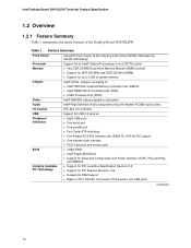
... for an Intel® Celeron® processor in an LGA775 socket • Two DDR SDRAM Dual Inline Memory Module (DIMM) sockets • Support for DDR 400 MHz and DDR 333 MHz DIMMs • Support for up to 2 GB of system memory Chipset Video Audio Intel® 910GL Chipset, consisting of the Desktop Board D910GLDW. Intel Desktop Board D910GLDW...
... for an Intel® Celeron® processor in an LGA775 socket • Two DDR SDRAM Dual Inline Memory Module (DIMM) sockets • Support for DDR 400 MHz and DDR 333 MHz DIMMs • Support for up to 2 GB of system memory Chipset Video Audio Intel® 910GL Chipset, consisting of the Desktop Board D910GLDW. Intel Desktop Board D910GLDW...
Product Specification
Page 13
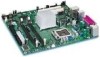
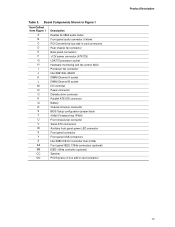
Board Components Shown in Figure 1 Item/Callout from Figure 1 A B C D E F G H I J K L M N O P Q R S T U V W X Y Z AA BB CC DD Description Realtek ALC860 audio codec Front panel audio connector (Yellow) PCI Conventional bus add-in card connectors Rear chassis fan connector Back panel connectors +12V power connector (ATX12V) LGA775 processor socket Hardware monitoring and fan control ASIC Processor fan connector Intel... Auxiliary front panel power LED connector Front panel connector Front panel USB connectors Intel 82801FB I/O Controller Hub (ICH6) Front panel IEEE-1394a connectors (optional) ...
Board Components Shown in Figure 1 Item/Callout from Figure 1 A B C D E F G H I J K L M N O P Q R S T U V W X Y Z AA BB CC DD Description Realtek ALC860 audio codec Front panel audio connector (Yellow) PCI Conventional bus add-in card connectors Rear chassis fan connector Back panel connectors +12V power connector (ATX12V) LGA775 processor socket Hardware monitoring and fan control ASIC Processor fan connector Intel... Auxiliary front panel power LED connector Front panel connector Front panel USB connectors Intel 82801FB I/O Controller Hub (ICH6) Front panel IEEE-1394a connectors (optional) ...
Product Specification
Page 14
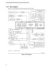
Block Diagram OM17307 14 Intel Desktop Board D910GLDW Technical Product Specification 1.2.4 Block Diagram Figure 2 is a block diagram of the major functional areas of the board. PCI Express x1 Slot 1 PCI Express x1 Interface Parallel ATA IDE Connector LGA775 Processor Socket Parallel ATA IDE Interface System Bus (533 MHz) USB Back Panel/Front Panel USB Ports LPC...
Block Diagram OM17307 14 Intel Desktop Board D910GLDW Technical Product Specification 1.2.4 Block Diagram Figure 2 is a block diagram of the major functional areas of the board. PCI Express x1 Slot 1 PCI Express x1 Interface Parallel ATA IDE Connector LGA775 Processor Socket Parallel ATA IDE Interface System Bus (533 MHz) USB Back Panel/Front Panel USB Ports LPC...
Product Specification
Page 15
...533 MHz system bus. See the Intel web site listed below for the Desktop Board D910GLDW Processor data sheets ICH6 addressing Custom splash ...intel.com/design/motherbd http://www.intel.com/design/motherbd 1.4 Processor The board is designed to -date list of unsupported processors can damage the board, the processor, and the power supply. # INTEGRATOR'S NOTE Use only ATX12V-compliant power supplies. Intel Desktop Board D910GLDW under "Desktop Board Products" or "Desktop Board Support" Available configurations for the most up-to support an Intel Celeron processor in an LGA775 processor...
...533 MHz system bus. See the Intel web site listed below for the Desktop Board D910GLDW Processor data sheets ICH6 addressing Custom splash ...intel.com/design/motherbd http://www.intel.com/design/motherbd 1.4 Processor The board is designed to -date list of unsupported processors can damage the board, the processor, and the power supply. # INTEGRATOR'S NOTE Use only ATX12V-compliant power supplies. Intel Desktop Board D910GLDW under "Desktop Board Products" or "Desktop Board Support" Available configurations for the most up-to support an Intel Celeron processor in an LGA775 processor...

Product Specification
Page 21
...sec. • ATA-66: DMA protocol on IDE bus supporting host and target throttling and transfer rates of 150 MB/s per channel. The board supports Laser Servo (LS-120) diskette technology through the Parallel ATA IDE interfaces. Product Description 1.6.3.1 Parallel ATE IDE Interface The ICH6's Parallel ... ATA-100 logic can operate in both legacy and native modes. In legacy mode, standard IDE I /O (PIO): processor controls data transfer. • 8237-style DMA: DMA offloads the processor, supporting transfer rates of up to 16 MB/sec. • Ultra DMA: DMA protocol on IDE bus supporting host...
...sec. • ATA-66: DMA protocol on IDE bus supporting host and target throttling and transfer rates of 150 MB/s per channel. The board supports Laser Servo (LS-120) diskette technology through the Parallel ATA IDE interfaces. Product Description 1.6.3.1 Parallel ATE IDE Interface The ICH6's Parallel ... ATA-100 logic can operate in both legacy and native modes. In legacy mode, standard IDE I /O (PIO): processor controls data transfer. • 8237-style DMA: DMA offloads the processor, supporting transfer rates of up to 16 MB/sec. • Ultra DMA: DMA protocol on IDE bus supporting host...
Product Specification
Page 27
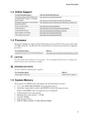
... Standard Format (ASF) Support The boards provide the following ASF support for PCI Express x1 bus add-in LAN cards and PCI Conventional bus add-in LAN cards installed in PCI Conventional bus slot 2: • Monitoring of system firmware progress events, including: ⎯ BIOS present ⎯ Primary processor initialization ⎯ Memory initialization... different types of boot devices • Reset, shutdown, power cycle, and power up options 1.10.3 LAN Subsystem Software LAN software and drivers are available from Intel's World Wide Web site.
... Standard Format (ASF) Support The boards provide the following ASF support for PCI Express x1 bus add-in LAN cards and PCI Conventional bus add-in LAN cards installed in PCI Conventional bus slot 2: • Monitoring of system firmware progress events, including: ⎯ BIOS present ⎯ Primary processor initialization ⎯ Memory initialization... different types of boot devices • Reset, shutdown, power cycle, and power up options 1.10.3 LAN Subsystem Software LAN software and drivers are available from Intel's World Wide Web site.

Product Specification
Page 28
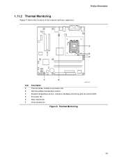
Intel Desktop Board D910GLDW Technical Product Specification 1.11 Hardware Management Subsystem The hardware management features enable the board to Figure 9, page 29 28 The Desktop Board has several hardware management features, including the following: • Fan monitoring and control (...hardware monitoring and fan control ASIC include: • Internal ambient temperature sensor • Two remote thermal diode sensors for direct monitoring of processor temperature and ambient temperature sensing • Power supply monitoring of five voltages (+5 V, +12 V, +3.3 VSB, +1.5 V, and +VCCP...
Intel Desktop Board D910GLDW Technical Product Specification 1.11 Hardware Management Subsystem The hardware management features enable the board to Figure 9, page 29 28 The Desktop Board has several hardware management features, including the following: • Fan monitoring and control (...hardware monitoring and fan control ASIC include: • Internal ambient temperature sensor • Two remote thermal diode sensors for direct monitoring of processor temperature and ambient temperature sensing • Power supply monitoring of five voltages (+5 V, +12 V, +3.3 VSB, +1.5 V, and +VCCP...
Product Specification
Page 29
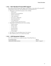
Product Description 3 1 A CB 4 1 D 1 3 Item A B C D E F F E OM17312 Description Thermal diode, located on processor die Remote ambient temperature sensor Ambient temperature sensor, internal to hardware monitoring and fan control ASIC Processor fan Rear chassis fan Front chassis fan Figure 9. Thermal Monitoring 29 1.11.2 Thermal Monitoring Figure 9 shows the location of the sensors and fan connectors.
Product Description 3 1 A CB 4 1 D 1 3 Item A B C D E F F E OM17312 Description Thermal diode, located on processor die Remote ambient temperature sensor Ambient temperature sensor, internal to hardware monitoring and fan control ASIC Processor fan Rear chassis fan Front chassis fan Figure 9. Thermal Monitoring 29 1.11.2 Thermal Monitoring Figure 9 shows the location of the sensors and fan connectors.
Product Specification
Page 30
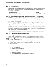
Intel Desktop Board D910GLDW Technical Product Specification 1.11.3 Fan Monitoring Fan monitoring can be implemented using the processor fan heat-sink included with the Desktop Board. It is attached to any ...desktop board BIOS. For information about The functions of monitoring and control is removed. Disabling the processor fan speed control will vary based on system configuration and environment. 1.11.5 Chassis Intrusion and Detection The board supports a chassis security feature that processor fan speed control remain enabled (default BIOS setting) when using Intel® Desktop...
Intel Desktop Board D910GLDW Technical Product Specification 1.11.3 Fan Monitoring Fan monitoring can be implemented using the processor fan heat-sink included with the Desktop Board. It is attached to any ...desktop board BIOS. For information about The functions of monitoring and control is removed. Disabling the processor fan speed control will vary based on system configuration and environment. 1.11.5 Chassis Intrusion and Detection The board supports a chassis security feature that processor fan speed control remain enabled (default BIOS setting) when using Intel® Desktop...

Product Specification
Page 32
...wake-up logic. No power to disk. Dependent on user preferences and knowledge of how devices are not being used in boards and peripherals powered by battery or external source. working C0 - Suspend to disk. sleeping state S4 - Notes: 1. Total...Processor stopped S3 - no power except for wake-up logic. No power D3 - The operating system puts devices in and out of low-power states based on the standby power consumption of the various system and power states. D3 - Full power > 30 W G1 - Context saved to the system. No power D3 - Intel Desktop Board...
...wake-up logic. No power to disk. Dependent on user preferences and knowledge of how devices are not being used in boards and peripherals powered by battery or external source. working C0 - Suspend to disk. sleeping state S4 - Notes: 1. Total...Processor stopped S3 - no power except for wake-up logic. No power D3 - The operating system puts devices in and out of low-power states based on the standby power consumption of the various system and power states. D3 - Full power > 30 W G1 - Context saved to the system. No power D3 - Intel Desktop Board...

Product Specification
Page 34
.... For information about The location of the fan connectors The location of the fan connectors and sensors for thermal monitoring The signal names of the processor fan connector The signal names of the fan connectors is as needed. • All fan connectors have a +12 V DC connection. For... returns to the power state it is in the BIOS Setup program's Boot menu. The computer's response can damage the power supply. 34 Intel Desktop Board D910GLDW Technical Product Specification Resume on Ring enables telephony devices to access the computer when it was in the S3, S4, or S5 state....
.... For information about The location of the fan connectors The location of the fan connectors and sensors for thermal monitoring The signal names of the processor fan connector The signal names of the fan connectors is as needed. • All fan connectors have a +12 V DC connection. For... returns to the power state it is in the BIOS Setup program's Boot menu. The computer's response can damage the power supply. 34 Intel Desktop Board D910GLDW Technical Product Specification Resume on Ring enables telephony devices to access the computer when it was in the S3, S4, or S5 state....
Product Specification
Page 46
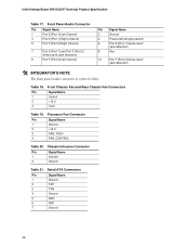
... 2 Ground Table 21. Processor Fan Connector Pin Signal Name 1 Ground 2 +12 V 3 FAN_TACH 4 FAN_CONTROL Table 20. Table 18. Front Chassis Fan and Rear Chassis Fan Connectors Pin Signal Name 1 Control 2 +12 V 3 Tach Table 19. Serial ATA Connectors Pin Signal Name 1 Ground 2 TXP 3 TXN 4 Ground 5 RXN 6 RXP 7 Ground 46 Intel Desktop Board D910GLDW Technical Product Specification...
... 2 Ground Table 21. Processor Fan Connector Pin Signal Name 1 Ground 2 +12 V 3 FAN_TACH 4 FAN_CONTROL Table 20. Table 18. Front Chassis Fan and Rear Chassis Fan Connectors Pin Signal Name 1 Control 2 +12 V 3 Tach Table 19. Serial ATA Connectors Pin Signal Name 1 Ground 2 TXP 3 TXN 4 Ground 5 RXN 6 RXP 7 Ground 46 Intel Desktop Board D910GLDW Technical Product Specification...
Product Specification
Page 47
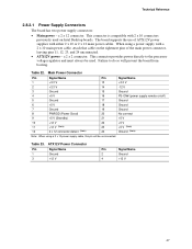
... 12 2 x 12 connector detect (Note) Pin Signal Name 13 +3.3 V 14 -12 V 15 Ground 16 PS-ON# (power supply remote on Intel Desktop boards. This connector provides power directly to do so will be used on /off) 17 Ground 18 Ground 19 Ground 20 No connect 21 +5 V 22 ..., and 24 unconnected. • ATX12V power - When using a 2 x 10 power supply cable, this pin will prevent the board from booting. Failure to the processor voltage regulator and must always be unconnected. a 2 x 2 connector. a 2 x 12 connector. Table 22. Technical Reference 2.8.2.1 Power ...
... 12 2 x 12 connector detect (Note) Pin Signal Name 13 +3.3 V 14 -12 V 15 Ground 16 PS-ON# (power supply remote on Intel Desktop boards. This connector provides power directly to do so will be used on /off) 17 Ground 18 Ground 19 Ground 20 No connect 21 +5 V 22 ..., and 24 unconnected. • ATX12V power - When using a 2 x 10 power supply cable, this pin will prevent the board from booting. Failure to the processor voltage regulator and must always be unconnected. a 2 x 2 connector. a 2 x 12 connector. Table 22. Technical Reference 2.8.2.1 Power ...
Product Specification
Page 52
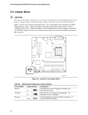
... for the three modes: normal, configure, and recovery. A 3 recovery diskette is displayed. The 3 maintenance menu is required. 52 Intel Desktop Board D910GLDW Technical Product Specification 2.9 Jumper Block CAUTION Do not move the jumper with the power on. Table 28 describes the jumper settings for...2-3 1 After the POST runs, Setup runs automatically. Location of the jumper block. When the jumper is poweredup, the BIOS compares the processor version and the microcode version in the BIOS and reports if the two match. 1 3 J8J4 OM17316 Figure 16. Recovery None 1 The...
... for the three modes: normal, configure, and recovery. A 3 recovery diskette is displayed. The 3 maintenance menu is required. 52 Intel Desktop Board D910GLDW Technical Product Specification 2.9 Jumper Block CAUTION Do not move the jumper with the power on. Table 28 describes the jumper settings for...2-3 1 After the POST runs, Setup runs automatically. Location of the jumper block. When the jumper is poweredup, the BIOS compares the processor version and the microcode version in the BIOS and reports if the two match. 1 3 J8J4 OM17316 Figure 16. Recovery None 1 The...

Product Specification
Page 55
... 30 lists the current capability of the board. Table 30. Maximum values assume a load placed on the board that is similar to the processor, memory, and USB ports. These calculations are not based on specific processor values or memory configurations but are based ... 2 A (average) of +5 V current for a fully loaded board (all active components within the board that will halt fan operation. Connecting the processor fan to a particular processor speed. Fan Connector Current Capability Fan Connector Processor fan Front chassis fan Rear chassis fan Maximum Available Current 1000 mA...
... 30 lists the current capability of the board. Table 30. Maximum values assume a load placed on the board that is similar to the processor, memory, and USB ports. These calculations are not based on specific processor values or memory configurations but are based ... 2 A (average) of +5 V current for a fully loaded board (all active components within the board that will halt fan operation. Connecting the processor fan to a particular processor speed. Fan Connector Current Capability Fan Connector Processor fan Front chassis fan Rear chassis fan Maximum Available Current 1000 mA...
Product Specification
Page 57
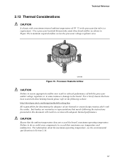
... at the processor fan inlet is a requirement. For a list of chassis that merely following website: http://developer.intel.com/design/motherbd/cooling.htm All responsibility for determining the adequacy of any thermal or system design remains solely with adequate thermal performance. Intel makes no warranties or representations that have been tested with Intel desktop boards please...
... at the processor fan inlet is a requirement. For a list of chassis that merely following website: http://developer.intel.com/design/motherbd/cooling.htm All responsibility for determining the adequacy of any thermal or system design remains solely with adequate thermal performance. Intel makes no warranties or representations that have been tested with Intel desktop boards please...


