
Product Specification
Page 5
...1.1 PCI Bus Terminology Change 11 1.2 Board Differences...11 1.3 Overview ...12 1.3.1 Feature Summary 12 1.3.2 Manufacturing Options 13 1.3.3 Board Layouts 14 1.3.4 Block Diagram 18 1.4 Online Support ...19 1.5 Processor ...19 1.6 System Memory ...20 1.6.1 Memory Configurations 21 1.7 Intel® 925X Chipset ...25 1.7.1 USB ...25 1.7.2 IDE Support 25 1.7.3 Real-Time Clock, CMOS SRAM, and Battery 28 1.8 PCI Express Connectors 28 1.9 Auxiliary Power (AUX PWR) Output Connector 28 1.10 I/O Controller...29 1.10.1 Serial Port ...29 1.10.2 Parallel Port 29 1.10.3 Diskette Drive Controller...
...1.1 PCI Bus Terminology Change 11 1.2 Board Differences...11 1.3 Overview ...12 1.3.1 Feature Summary 12 1.3.2 Manufacturing Options 13 1.3.3 Board Layouts 14 1.3.4 Block Diagram 18 1.4 Online Support ...19 1.5 Processor ...19 1.6 System Memory ...20 1.6.1 Memory Configurations 21 1.7 Intel® 925X Chipset ...25 1.7.1 USB ...25 1.7.2 IDE Support 25 1.7.3 Real-Time Clock, CMOS SRAM, and Battery 28 1.8 PCI Express Connectors 28 1.9 Auxiliary Power (AUX PWR) Output Connector 28 1.10 I/O Controller...29 1.10.1 Serial Port ...29 1.10.2 Parallel Port 29 1.10.3 Diskette Drive Controller...

Product Specification
Page 8
...) Mode Configuration with Three DIMMs 22 7. LAN Connector LED Locations 35 15. Location of Pressing the Power Switch 41 9. D925XBC Component-side Connectors 70 23. Connection Diagram for 6-Channel (5.1) Audio Subsystem ....34 13. 6-Channel (5.1) Audio Subsystem Block Diagram 34 14. Localized High Temperature Zones 88 Tables 1. Memory Channel and DIMM Configuration 21 5. Front/Back Panel Audio Connector Options for Front Panel Connector 77 24. I /O Shield Dimensions for Omni-directional Airflow 87 32. LAN Connector LED States 35 8. Wake-up Devices and...
...) Mode Configuration with Three DIMMs 22 7. LAN Connector LED Locations 35 15. Location of Pressing the Power Switch 41 9. D925XBC Component-side Connectors 70 23. Connection Diagram for 6-Channel (5.1) Audio Subsystem ....34 13. 6-Channel (5.1) Audio Subsystem Block Diagram 34 14. Localized High Temperature Zones 88 Tables 1. Memory Channel and DIMM Configuration 21 5. Front/Back Panel Audio Connector Options for Front Panel Connector 77 24. I /O Shield Dimensions for Omni-directional Airflow 87 32. LAN Connector LED States 35 8. Wake-up Devices and...

Product Specification
Page 9
.... BIOS Setup Configuration Jumper Settings 80 37. Thermal Considerations for a One-Color Power LED 77 35. Supervisor and User Password Functions 101 48. Back Panel Connectors Shown in Figure 21 69 20. Uncompressed INIT Code Checkpoints 105 50. I/O Map ...58 14. SCSI Hard Drive Activity LED Connector (Optional 73 27. EMC Regulations ...91 43. Runtime Code Uncompressed in F000 Shadow RAM 106 52. Main Power Connector 75 30. Safety Regulations ...91 42. Desktop Boards...
.... BIOS Setup Configuration Jumper Settings 80 37. Thermal Considerations for a One-Color Power LED 77 35. Supervisor and User Password Functions 101 48. Back Panel Connectors Shown in Figure 21 69 20. Uncompressed INIT Code Checkpoints 105 50. I/O Map ...58 14. SCSI Hard Drive Activity LED Connector (Optional 73 27. EMC Regulations ...91 43. Runtime Code Uncompressed in F000 Shadow RAM 106 52. Main Power Connector 75 30. Safety Regulations ...91 42. Desktop Boards...

Product Specification
Page 11
... Contains 1.1 PCI Bus Terminology Change 11 1.2 Board Differences...11 1.3 Overview ...12 1.4 Online Support ...19 1.5 Processor ...19 1.6 System Memory ...20 1.7 Intel® 925X Chipset 25 1.8 PCI Express Connectors 28 1.9 Auxiliary Power (AUX PWR) Output Connector 28 1.10 I/O Controller...29 1.11 Audio Subsystem ...31 1.12 LAN Subsystem...35 1.13 Hardware Management Subsystem 37 1.14 Power Management 40 1.15 Trusted Platform Module (Optional 47 1.1 PCI Bus Terminology Change Previous generations of Intel Desktop Boards adds a new technology for Trusted...
... Contains 1.1 PCI Bus Terminology Change 11 1.2 Board Differences...11 1.3 Overview ...12 1.4 Online Support ...19 1.5 Processor ...19 1.6 System Memory ...20 1.7 Intel® 925X Chipset 25 1.8 PCI Express Connectors 28 1.9 Auxiliary Power (AUX PWR) Output Connector 28 1.10 I/O Controller...29 1.11 Audio Subsystem ...31 1.12 LAN Subsystem...35 1.13 Hardware Management Subsystem 37 1.14 Power Management 40 1.15 Trusted Platform Module (Optional 47 1.1 PCI Bus Terminology Change Previous generations of Intel Desktop Boards adds a new technology for Trusted...

Product Specification
Page 13
...-in card connector, and one PCI Express x16 bus add-in hard drive controllers (SCSI or other) to use the same LED as the onboard IDE controller. (D925XCV board only) Trusted Platform Module (TPM) A component that enhances platform security (D925XCV board only) For information about Available configurations for internal chassis lighting (D925XCV board only) IEEE-1394a Interface IEEE-1394a controller and three IEEE-1394a connectors (one of range thermal values • Three fan connectors...
...-in card connector, and one PCI Express x16 bus add-in hard drive controllers (SCSI or other) to use the same LED as the onboard IDE controller. (D925XCV board only) Trusted Platform Module (TPM) A component that enhances platform security (D925XCV board only) For information about Available configurations for internal chassis lighting (D925XCV board only) IEEE-1394a Interface IEEE-1394a controller and three IEEE-1394a connectors (one of range thermal values • Three fan connectors...

Product Specification
Page 18
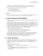
... Processor Socket System Bus (800/533 MHz) PCI Express x16 Interface PCI Express x16 Connector Intel 82925X Memory Controller Hub (MCH) Channel A DIMMs (2) Channel B DIMMs (2) Dual-Channel Memory Bus SMBus DMI Interconnect Gigabit Ethernet Controller LAN Connector USB Back Panel/Front Panel USB Ports LPC Bus I/O Controller LPC Bus Serial Ports Parallel Port PS/2 Mouse PS/2 Keyboard Diskette Drive Connector Intel 82801FR I/O Controller Hub (ICH6-R) 8 Mbit Firmware Hub (FWH) LPC Bus Intel 925X Chipset TPM Component (Optional) Serial ATA IDE Interface Serial ATA IDE Connectors...
... Processor Socket System Bus (800/533 MHz) PCI Express x16 Interface PCI Express x16 Connector Intel 82925X Memory Controller Hub (MCH) Channel A DIMMs (2) Channel B DIMMs (2) Dual-Channel Memory Bus SMBus DMI Interconnect Gigabit Ethernet Controller LAN Connector USB Back Panel/Front Panel USB Ports LPC Bus I/O Controller LPC Bus Serial Ports Parallel Port PS/2 Mouse PS/2 Keyboard Diskette Drive Connector Intel 82801FR I/O Controller Hub (ICH6-R) 8 Mbit Firmware Hub (FWH) LPC Bus Intel 925X Chipset TPM Component (Optional) Serial ATA IDE Interface Serial ATA IDE Connectors...
Product Specification
Page 27
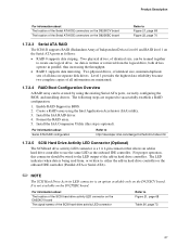
.... 1.7.2.4 RAID Boot Configuration Overview A RAID array can be wired to create one logical drive. Create a RAID array using the existing Serial ATA ports, correctly configuring the BIOS, and installing drivers. Install the IAA RAID driver. 4. It is optional). Install the IAA Companion Utility (this connector should be teamed together to the LED output of the add-in hard drive controller. Enable RAID Support in parallel, thus increasing the throughput. • RAID 1 supports data mirroring. Two physical drives, of identical size, maintain duplicate sets...
.... 1.7.2.4 RAID Boot Configuration Overview A RAID array can be wired to create one logical drive. Create a RAID array using the existing Serial ATA ports, correctly configuring the BIOS, and installing drivers. Install the IAA RAID driver. 4. It is optional). Install the IAA Companion Utility (this connector should be teamed together to the LED output of the add-in hard drive controller. Enable RAID Support in parallel, thus increasing the throughput. • RAID 1 supports data mirroring. Two physical drives, of identical size, maintain duplicate sets...
Product Specification
Page 28
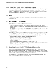
...; Software compatible with a 24-pin (2x12) main power cable. The on . 1.8 PCI Express Connectors The boards provide the following : • Support for the PCI Express enhanced configuration mechanism • Automatic discovery, link training, and initialization • Support for internal chassis lighting or additional fans. The clock is not plugged into CMOS RAM at 25 ºC with 3.3 VSB applied. ✏ NOTE If the battery and AC power fail, custom defaults, if previously saved, will be used , the auxiliary power...
...; Software compatible with a 24-pin (2x12) main power cable. The on . 1.8 PCI Express Connectors The boards provide the following : • Support for the PCI Express enhanced configuration mechanism • Automatic discovery, link training, and initialization • Support for internal chassis lighting or additional fans. The clock is not plugged into CMOS RAM at 25 ºC with 3.3 VSB applied. ✏ NOTE If the battery and AC power fail, custom defaults, if previously saved, will be used , the auxiliary power...

Product Specification
Page 51
... using the Key Transfer Manager when the removable media is necessary. 1.15.7.2 Recovering from Desktop Board or TPM Failure This procedure may restore the migratable keys from the previously created Recovery Archives. 1. Follow the instructions and create and document the locations for both the archive and restoration key files. Create and document the password to create the archive and restoration key files. 18. If the removable...
... using the Key Transfer Manager when the removable media is necessary. 1.15.7.2 Recovering from Desktop Board or TPM Failure This procedure may restore the migratable keys from the previously created Recovery Archives. 1. Follow the instructions and create and document the locations for both the archive and restoration key files. Create and document the password to create the archive and restoration key files. 18. If the removable...

Product Specification
Page 52
... the front panel power switch is disabled by the Key Transfer Manager. 11. When cleared, the TPM module is off the system. 9. Observe precautions in the lower right corner of the wizard. 8. Intel Desktop Boards D925XCV/D925XBC Technical Product Specification 4. Follow the instructions during the Security Platform Initialization, and append the Emergency Recovery Archive to change my Personal Secure Drive setting", confirm the drive letter and...
... the front panel power switch is disabled by the Key Transfer Manager. 11. When cleared, the TPM module is off the system. 9. Observe precautions in the lower right corner of the wizard. 8. Intel Desktop Boards D925XCV/D925XBC Technical Product Specification 4. Follow the instructions during the Security Platform Initialization, and append the Emergency Recovery Archive to change my Personal Secure Drive setting", confirm the drive letter and...

Product Specification
Page 63
... into these connectors to power devices external to the computer, the power cable, and the external devices themselves. Technical Reference 2.8 Connectors CAUTION Only the following connectors have overcurrent protection: back panel USB, front panel USB, and PS/2. The other internal connectors are installed at least 1.5 inches above the main power connector, the diskette drive connector, the Parallel ATA IDE connector, and the DIMM sockets. 2.8.1 Back Panel Connectors The back panel configuration is dependent upon which audio subsystem is...
... into these connectors to power devices external to the computer, the power cable, and the external devices themselves. Technical Reference 2.8 Connectors CAUTION Only the following connectors have overcurrent protection: back panel USB, front panel USB, and PS/2. The other internal connectors are installed at least 1.5 inches above the main power connector, the diskette drive connector, the Parallel ATA IDE connector, and the DIMM sockets. 2.8.1 Back Panel Connectors The back panel configuration is dependent upon which audio subsystem is...

Product Specification
Page 95
... 3.5 Legacy USB Support 97 3.6 BIOS Updates ...98 3.7 Boot Options ...99 3.8 Fast Booting Systems with Intel® Rapid BIOS Boot 100 3.9 BIOS Security Features 101 3.1 Introduction The Desktop Boards D925XCV and D925XBC use an Intel/AMI BIOS that is stored in the Firmware Hub (FWH) and can be updated using a disk-based program. The FWH contains the BIOS Setup program, POST, the PCI auto-configuration utility, and Plug and Play support. Maintenance Main Advanced Security Power Boot Exit ✏ NOTE The maintenance menu is displayed only...
... 3.5 Legacy USB Support 97 3.6 BIOS Updates ...98 3.7 Boot Options ...99 3.8 Fast Booting Systems with Intel® Rapid BIOS Boot 100 3.9 BIOS Security Features 101 3.1 Introduction The Desktop Boards D925XCV and D925XBC use an Intel/AMI BIOS that is stored in the Firmware Hub (FWH) and can be updated using a disk-based program. The FWH contains the BIOS Setup program, POST, the PCI auto-configuration utility, and Plug and Play support. Maintenance Main Advanced Security Power Boot Exit ✏ NOTE The maintenance menu is displayed only...

Product Specification
Page 96
... Load the default configuration values for menu screens. BIOS Setup Program Menu Bar Maintenance Main Advanced Security Clears passwords and displays processor information Displays processor and memory configuration Configures advanced features available through the chipset Sets passwords and security features Power Boot Configures power management features and power supply controls Selects boot options Exit Saves or discards changes to optimize capacity and performance. When a user turns on the system after adding a PCI card, the BIOS automatically configures interrupts...
... Load the default configuration values for menu screens. BIOS Setup Program Menu Bar Maintenance Main Advanced Security Clears passwords and displays processor information Displays processor and memory configuration Configures advanced features available through the chipset Sets passwords and security features Power Boot Configures power management features and power supply controls Selects boot options Exit Saves or discards changes to optimize capacity and performance. When a user turns on the system after adding a PCI card, the BIOS automatically configures interrupts...
Product Specification
Page 97
... enter and configure the BIOS Setup program and the maintenance menu. 4. Legacy USB support operates as an ATAPI master device. POST completes. 97 For example, do not connect an ATA hard drive as Windows NT*, require an additional interface for accessing this support, an SMBIOS service-level application running on the same IDE cable as follows: 1. Legacy USB support is a Desktop Management Interface (DMI) compliant method for managing computers in the BIOS Setup program. By default, Legacy USB support...
... enter and configure the BIOS Setup program and the maintenance menu. 4. Legacy USB support operates as an ATAPI master device. POST completes. 97 For example, do not connect an ATA hard drive as Windows NT*, require an additional interface for accessing this support, an SMBIOS service-level application running on the same IDE cable as follows: 1. Legacy USB support is a Desktop Management Interface (DMI) compliant method for managing computers in the BIOS Setup program. By default, Legacy USB support...

Product Specification
Page 100
... Boot Menu: • Set the hard disk drive as "power-up to four seconds of option ROM boot time. ✏ NOTE It is possible to introduce a programmable delay ranging from the POST execution time. • Disable Quiet Boot, which eliminates display of painting complex graphic images and changing video modes. • Enable Intel Rapid BIOS Boot. This can reduce up to 30 seconds (using the Hard Disk Pre-Delay feature of the Advanced Menu in POST. Monitors and hard disk drives...
... Boot Menu: • Set the hard disk drive as "power-up to four seconds of option ROM boot time. ✏ NOTE It is possible to introduce a programmable delay ranging from the POST execution time. • Disable Quiet Boot, which eliminates display of painting complex graphic images and changing video modes. • Enable Intel Rapid BIOS Boot. This can reduce up to 30 seconds (using the Hard Disk Pre-Delay feature of the Advanced Menu in POST. Monitors and hard disk drives...

Product Specification
Page 104
... keyboard connection. NVRAM was removed then memory may be powered down and the jumper removed. Updated Failed NVRAM was invalid but was added there may be updated. Memory Size Changed Memory size has changed since the last boot. Make sure keyboard is followed by NVRAM, CMOS, and passwords have been cleared. On Board Parity Error Parity Error A parity error occurred in onboard memory. BIOS Error Messages (continued) Error Message Explanation Update OK! If no memory was unable to boot. This error is connected properly. Intel Desktop Boards...
... keyboard connection. NVRAM was removed then memory may be powered down and the jumper removed. Updated Failed NVRAM was invalid but was added there may be updated. Memory Size Changed Memory size has changed since the last boot. Make sure keyboard is followed by NVRAM, CMOS, and passwords have been cleared. On Board Parity Error Parity Error A parity error occurred in onboard memory. BIOS Error Messages (continued) Error Message Explanation Update OK! If no memory was unable to boot. This error is connected properly. Intel Desktop Boards...

Product Specification
Page 105
... display. ✏ NOTE The POST card must be transferred to main BIOS. Some codes are repeated in F000 shadow RAM. Table 49. Init code Checksum verification starting. Verify base memory. Initialize extra (Intel Recovery) Module. Booting from floppy. Try to recovery code in PCI bus connector 1. This code is left at port 80h. Onboard KBC, RTC enabled (if present). Give two beeps. To check recovery mode and verify main BIOS checksum. Keyboard controller BAT test, CPU ID saved, and going to I/O port...
... display. ✏ NOTE The POST card must be transferred to main BIOS. Some codes are repeated in F000 shadow RAM. Table 49. Init code Checksum verification starting. Verify base memory. Initialize extra (Intel Recovery) Module. Booting from floppy. Try to recovery code in PCI bus connector 1. This code is left at port 80h. Onboard KBC, RTC enabled (if present). Give two beeps. To check recovery mode and verify main BIOS checksum. Keyboard controller BAT test, CPU ID saved, and going to I/O port...
Product Specification
Page 106
... of , key during power-on. 12 To init CMOS if "Init CMOS in F000 Shadow RAM Code Description of different buses.) 3A New cursor position read 8042 input port and disable Megakey GreenPC feature. To do alternate Display memory R/W test. 32 Alternate Display memory R/W test passed. Chipset init about to begin . 30 Display memory R/W test passed. Runtime Code Uncompressed in every boot" is set or key is initialized. Intel Desktop Boards D925XCV...
... of , key during power-on. 12 To init CMOS if "Init CMOS in F000 Shadow RAM Code Description of different buses.) 3A New cursor position read 8042 input port and disable Megakey GreenPC feature. To do alternate Display memory R/W test. 32 Alternate Display memory R/W test passed. Chipset init about to begin . 30 Display memory R/W test passed. Runtime Code Uncompressed in every boot" is set or key is initialized. Intel Desktop Boards D925XCV...

Product Specification
Page 107
.... To check for diagnostics mode. Error Messages and Beep Codes Table 51. To enter in real mode. About to go to display the first 64k memory size. Going to find out amount of memory below 1M cleared. (SOFT RESET) Going to test memory. Memory below 1M memory. Going to follow. Memory test above 1M. Shutdown successful, CPU in virtual mode for relocation/shadow. Hit message cleared. DMA page register test...
.... To check for diagnostics mode. Error Messages and Beep Codes Table 51. To enter in real mode. About to go to display the first 64k memory size. Going to find out amount of memory below 1M cleared. (SOFT RESET) Going to test memory. Memory below 1M memory. Going to follow. Memory test above 1M. Shutdown successful, CPU in virtual mode for relocation/shadow. Hit message cleared. DMA page register test...
Product Specification
Page 110
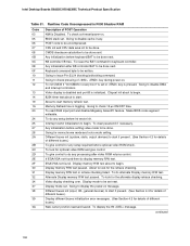
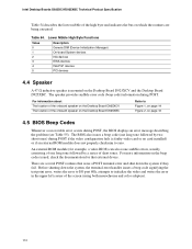
... video card or no card installed) or if an external ROM module does not properly checksum to initialize the video and writes the error in the upper left corner of the screen (using both monochrome and color adapters). 110 Table 54. There are being executed. The speaker provides audible error code (beep code) information during POST, the BIOS displays an error message describing the problem (see Table 55). Intel Desktop Boards D925XCV...
... video card or no card installed) or if an external ROM module does not properly checksum to initialize the video and writes the error in the upper left corner of the screen (using both monochrome and color adapters). 110 Table 54. There are being executed. The speaker provides audible error code (beep code) information during POST, the BIOS displays an error message describing the problem (see Table 55). Intel Desktop Boards D925XCV...


