
Product Specification
Page 5
... 11 1.2 Board Differences...11 1.3 Overview ...12 1.3.1 Feature Summary 12 1.3.2 Manufacturing Options 13 1.3.3 Board Layouts 14 1.3.4 Block Diagram 18 1.4 Online Support ...19 1.5 Processor ...19 1.6 System Memory ...20 1.6.1 Memory Configurations 21 1.7 Intel® 925X Chipset ...25 1.7.1 USB ...25 1.7.2 IDE Support 25 1.7.3 Real-Time Clock, CMOS SRAM, and Battery 28 1.8 PCI Express Connectors 28 1.9 Auxiliary...
... 11 1.2 Board Differences...11 1.3 Overview ...12 1.3.1 Feature Summary 12 1.3.2 Manufacturing Options 13 1.3.3 Board Layouts 14 1.3.4 Block Diagram 18 1.4 Online Support ...19 1.5 Processor ...19 1.6 System Memory ...20 1.6.1 Memory Configurations 21 1.7 Intel® 925X Chipset ...25 1.7.1 USB ...25 1.7.2 IDE Support 25 1.7.3 Real-Time Clock, CMOS SRAM, and Battery 28 1.8 PCI Express Connectors 28 1.9 Auxiliary...

Product Specification
Page 8
... 8-Channel (7.1) Audio Subsystem ....32 11. 8-channel (7.1) Audio Subsystem Block Diagram 33 12. Detailed System Memory Address Map 56 19. Intel Desktop Boards D925XCV/D925XBC Technical Product Specification Figures 1. Block Diagram ...18 4. Dual Channel (Interleaved) Mode Configuration with the 6-Channel (5.1) ...directional Airflow 87 32. D925XCV Component-side Connectors 68 22. D925XBC Component-side Connectors 70 23. Processor Heatsink for 8-Channel (7.1) Audio Subsystem 64 20. Manufacturing Options 13 4. LAN Connector LED States 35 8. Effects of Board ...
... 8-Channel (7.1) Audio Subsystem ....32 11. 8-channel (7.1) Audio Subsystem Block Diagram 33 12. Detailed System Memory Address Map 56 19. Intel Desktop Boards D925XCV/D925XBC Technical Product Specification Figures 1. Block Diagram ...18 4. Dual Channel (Interleaved) Mode Configuration with the 6-Channel (5.1) ...directional Airflow 87 32. D925XCV Component-side Connectors 68 22. D925XBC Component-side Connectors 70 23. Processor Heatsink for 8-Channel (7.1) Audio Subsystem 64 20. Manufacturing Options 13 4. LAN Connector LED States 35 8. Effects of Board ...

Product Specification
Page 9
... Error Messages 103 49. BIOS Setup Configuration Jumper Settings 80 37. Boot Block Recovery Code Checkpoints 105 51. Lower Nibble High Byte Functions 110 55. Processor Fan Connector and Auxiliary Rear Fan Connector 72 25. Auxiliary Power Output Connector 73 29. Bus Initialization Checkpoints 109 53. Beep Codes ...111 ix Interrupts...
... Error Messages 103 49. BIOS Setup Configuration Jumper Settings 80 37. Boot Block Recovery Code Checkpoints 105 51. Lower Nibble High Byte Functions 110 55. Processor Fan Connector and Auxiliary Rear Fan Connector 72 25. Auxiliary Power Output Connector 73 29. Bus Initialization Checkpoints 109 53. Beep Codes ...111 ix Interrupts...

Product Specification
Page 11
...output connector • Option for SCSI hard drive indicator LED • Option for add-in card connector 11 This generation of Intel Desktop Boards adds a new technology for Trusted Platform Module (TPM) • microATX Form Factor (9.60 inches by 9.60 ... Description What This Chapter Contains 1.1 PCI Bus Terminology Change 11 1.2 Board Differences...11 1.3 Overview ...12 1.4 Online Support ...19 1.5 Processor ...19 1.6 System Memory ...20 1.7 Intel® 925X Chipset 25 1.8 PCI Express Connectors 28 1.9 Auxiliary Power (AUX PWR) Output Connector 28 1.10 I/O Controller...29 1.11...
...output connector • Option for SCSI hard drive indicator LED • Option for add-in card connector 11 This generation of Intel Desktop Boards adds a new technology for Trusted Platform Module (TPM) • microATX Form Factor (9.60 inches by 9.60 ... Description What This Chapter Contains 1.1 PCI Bus Terminology Change 11 1.2 Board Differences...11 1.3 Overview ...12 1.4 Online Support ...19 1.5 Processor ...19 1.6 System Memory ...20 1.7 Intel® 925X Chipset 25 1.8 PCI Express Connectors 28 1.9 Auxiliary Power (AUX PWR) Output Connector 28 1.10 I/O Controller...29 1.11...

Product Specification
Page 12
....84 millimeters by 243.84 millimeters]) Support for an Intel® Pentium® 4 processor in an LGA775 socket with an 800 or 533 MHz system bus • Four 240-pin DDR2 SDRAM Dual Inline Memory Module (DIMM) sockets • Support for DDR2 400 MHz and DDR2 533 MHz DIMMs • Support for PCI Express Revision...
....84 millimeters by 243.84 millimeters]) Support for an Intel® Pentium® 4 processor in an LGA775 socket with an 800 or 533 MHz system bus • Four 240-pin DDR2 SDRAM Dual Inline Memory Module (DIMM) sockets • Support for DDR2 400 MHz and DDR2 533 MHz DIMMs • Support for PCI Express Revision...

Product Specification
Page 15
...in card connector I Rear chassis fan connector J Back panel connectors K Alternate power connector L +12V power connector (ATX12V) M LGA775 processor socket N Processor fan connector O Intel 82925X MCH P DIMM Channel A sockets Q DIMM Channel B sockets R I/O controller S Power connector T Diskette drive connector U Parallel ... connector (optional) FF Front panel USB connector GG TPM component (optional) HH Front panel USB connector II Intel 82801FR I/O Controller Hub (ICH6-R) JJ Front panel IEEE-1394a connectors (optional) KK IEEE-1394a controller (optional...
...in card connector I Rear chassis fan connector J Back panel connectors K Alternate power connector L +12V power connector (ATX12V) M LGA775 processor socket N Processor fan connector O Intel 82925X MCH P DIMM Channel A sockets Q DIMM Channel B sockets R I/O controller S Power connector T Diskette drive connector U Parallel ... connector (optional) FF Front panel USB connector GG TPM component (optional) HH Front panel USB connector II Intel 82801FR I/O Controller Hub (ICH6-R) JJ Front panel IEEE-1394a connectors (optional) KK IEEE-1394a controller (optional...

Product Specification
Page 17
... card connector F Rear chassis fan connector G Back panel connectors H Alternate power connector I +12V power connector (ATX12V) J LGA775 processor socket K Processor fan connector L Intel 82925X MCH M DIMM Channel A sockets N DIMM Channel B sockets O I/O controller P Power connector Q Diskette drive connector R Parallel... panel power LED connector Z Front panel connector AA Front panel USB connector BB Front panel USB connector CC Intel 82801FR I/O Controller Hub (ICH6-R) DD Front panel IEEE-1394a connectors (optional) EE IEEE-1394a controller (optional...
... card connector F Rear chassis fan connector G Back panel connectors H Alternate power connector I +12V power connector (ATX12V) J LGA775 processor socket K Processor fan connector L Intel 82925X MCH M DIMM Channel A sockets N DIMM Channel B sockets O I/O controller P Power connector Q Diskette drive connector R Parallel... panel power LED connector Z Front panel connector AA Front panel USB connector BB Front panel USB connector CC Intel 82801FR I/O Controller Hub (ICH6-R) DD Front panel IEEE-1394a connectors (optional) EE IEEE-1394a controller (optional...

Product Specification
Page 18
... PCI Express x1 Slot 2 D925XCV only Parallel ATA IDE Connector Parallel ATA IDE Interface LGA775 Processor Socket System Bus (800/533 MHz) PCI Express x16 Interface PCI Express x16 Connector Intel 82925X Memory Controller Hub (MCH) Channel A DIMMs (2) Channel B DIMMs (2) Dual-Channel ...Bus I/O Controller LPC Bus Serial Ports Parallel Port PS/2 Mouse PS/2 Keyboard Diskette Drive Connector Intel 82801FR I/O Controller Hub (ICH6-R) 8 Mbit Firmware Hub (FWH) LPC Bus Intel 925X Chipset TPM Component (Optional) Serial ATA IDE Interface Serial ATA IDE Connectors (4) High Definition...
... PCI Express x1 Slot 2 D925XCV only Parallel ATA IDE Connector Parallel ATA IDE Interface LGA775 Processor Socket System Bus (800/533 MHz) PCI Express x16 Interface PCI Express x16 Connector Intel 82925X Memory Controller Hub (MCH) Channel A DIMMs (2) Channel B DIMMs (2) Dual-Channel ...Bus I/O Controller LPC Bus Serial Ports Parallel Port PS/2 Mouse PS/2 Keyboard Diskette Drive Connector Intel 82801FR I/O Controller Hub (ICH6-R) 8 Mbit Firmware Hub (FWH) LPC Bus Intel 925X Chipset TPM Component (Optional) Serial ATA IDE Interface Serial ATA IDE Connectors (4) High Definition...
Product Specification
Page 19
.../motherbd/bc/bc_available.htm http://www.intel.com/design/litcentr http://developer.intel.com/design/chipsets/datashts http://intel.com/design/motherbd/gen_indx.htm http://www.intel.com/design/motherbd http://www.intel.com/design/motherbd 1.5 Processor The boards are designed to -date list of unsupported processors can damage the board, the processor, and the power supply. # INTEGRATOR...
.../motherbd/bc/bc_available.htm http://www.intel.com/design/litcentr http://developer.intel.com/design/chipsets/datashts http://intel.com/design/motherbd/gen_indx.htm http://www.intel.com/design/motherbd http://www.intel.com/design/motherbd 1.5 Processor The boards are designed to -date list of unsupported processors can damage the board, the processor, and the power supply. # INTEGRATOR...

Product Specification
Page 25
... and EHCI, and uses UHCI- The Parallel ATA IDE interface supports the following devices: • Intel 82925X Memory Controller Hub (MCH) with Direct Media Interface (DMI) interconnect • Intel 82801FR I/O Controller Hub (ICH6-R) with dual stacked back panel connectors adjacent to the audio connectors ...a centralized controller for all ports. The ICH6-R provides the USB controller for the board's I/O paths. Product Description 1.7 Intel® 925X Chipset The Intel 925X chipset consists of the following modes: • Programmed I/O (PIO): processor controls data transfer. 25
... and EHCI, and uses UHCI- The Parallel ATA IDE interface supports the following devices: • Intel 82925X Memory Controller Hub (MCH) with Direct Media Interface (DMI) interconnect • Intel 82801FR I/O Controller Hub (ICH6-R) with dual stacked back panel connectors adjacent to the audio connectors ...a centralized controller for all ports. The ICH6-R provides the USB controller for the board's I/O paths. Product Description 1.7 Intel® 925X Chipset The Intel 925X chipset consists of the following modes: • Programmed I/O (PIO): processor controls data transfer. 25
Product Specification
Page 26
... D925XCV board The location of four Serial ATA devices. For more information, see: http://www.serialata.org/ 26 Intel Desktop Boards D925XCV/D925XBC Technical Product Specification • 8237-style DMA: DMA offloads the processor, supporting transfer rates of up to 16 MB/sec. • Ultra DMA: DMA protocol on IDE bus supporting...
... D925XCV board The location of four Serial ATA devices. For more information, see: http://www.serialata.org/ 26 Intel Desktop Boards D925XCV/D925XBC Technical Product Specification • 8237-style DMA: DMA offloads the processor, supporting transfer rates of up to 16 MB/sec. • Ultra DMA: DMA protocol on IDE bus supporting...

Product Specification
Page 36
...power cycle, and power up options 1.12.4 LAN Subsystem Software LAN software and drivers are available from Intel's World Wide Web site. Intel Desktop Boards D925XCV/D925XBC Technical Product Specification 1.12.3 Alert Standard Format (ASF) Support The boards provide ... in PCI Conventional bus slot 2: • Monitoring of system firmware progress events, including: BIOS present Primary processor initialization Memory initialization Video initialization PCI resource configuration Hard-disk initialization User authentication ...
...power cycle, and power up options 1.12.4 LAN Subsystem Software LAN software and drivers are available from Intel's World Wide Web site. Intel Desktop Boards D925XCV/D925XBC Technical Product Specification 1.12.3 Alert Standard Format (ASF) Support The boards provide ... in PCI Conventional bus slot 2: • Monitoring of system firmware progress events, including: BIOS present Primary processor initialization Memory initialization Video initialization PCI resource configuration Hard-disk initialization User authentication ...

Product Specification
Page 37
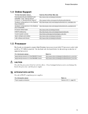
... features of the hardware monitoring and fan control ASIC include: • Internal ambient temperature sensor • Two remote thermal diode sensors for direct monitoring of processor temperature and ambient temperature sensing • Power supply monitoring of five voltages (+5 V, +12 V, +3.3 VSB, +1.5 V, and +VCCP) to Figure 15, page 38 Figure 16, page 39...
... features of the hardware monitoring and fan control ASIC include: • Internal ambient temperature sensor • Two remote thermal diode sensors for direct monitoring of processor temperature and ambient temperature sensing • Power supply monitoring of five voltages (+5 V, +12 V, +3.3 VSB, +1.5 V, and +VCCP) to Figure 15, page 38 Figure 16, page 39...

Product Specification
Page 38
Thermal Monitoring for D925XCV Board 38 G 4 1 A 3 1 B C 4 1 D 1 3 Item A B C D E F G F E OM16679 Description Remote ambient temperature sensor Thermal diode, located on the D925XCV board. Intel Desktop Boards D925XCV/D925XBC Technical Product Specification 1.13.2 Thermal Monitoring Figure 15 shows the location of the sensors and fan connectors on processor die Ambient temperature sensor, internal to hardware monitoring and fan control ASIC Processor fan connector Rear chassis fan connector Front chassis fan connector Auxiliary rear fan connector Figure 15.
Thermal Monitoring for D925XCV Board 38 G 4 1 A 3 1 B C 4 1 D 1 3 Item A B C D E F G F E OM16679 Description Remote ambient temperature sensor Thermal diode, located on the D925XCV board. Intel Desktop Boards D925XCV/D925XBC Technical Product Specification 1.13.2 Thermal Monitoring Figure 15 shows the location of the sensors and fan connectors on processor die Ambient temperature sensor, internal to hardware monitoring and fan control ASIC Processor fan connector Rear chassis fan connector Front chassis fan connector Auxiliary rear fan connector Figure 15.

Product Specification
Page 39
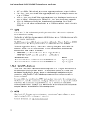
Thermal Monitoring for D925XBC Board 39 A 3 1 B C 4 1 D 1 3 F E Item A B C D E F OM16689 Description Remote ambient temperature sensor Thermal diode, located on the D925XBC board. Product Description Figure 16 shows the location of the sensors and fan connectors on processor die Ambient temperature sensor, internal to hardware monitoring and fan control ASIC Processor fan Rear chassis fan Front chassis fan Figure 16.
Thermal Monitoring for D925XBC Board 39 A 3 1 B C 4 1 D 1 3 F E Item A B C D E F OM16689 Description Remote ambient temperature sensor Thermal diode, located on the D925XBC board. Product Description Figure 16 shows the location of the sensors and fan connectors on processor die Ambient temperature sensor, internal to hardware monitoring and fan control ASIC Processor fan Rear chassis fan Front chassis fan Figure 16.

Product Specification
Page 42
...1. Power States and Targeted System Power Global States G0 - sleeping state G1 - Context saved to the system. Context saved to RAM. Processor States C0 - device specification specific. D3 - no power except for wake-up logic, except when provided by battery or external source. ... Table 9. no power for a complete description of wake-up logic. No power to disk. Processor stopped S3 - D3 - See the ACPI specification for wake-up logic. Intel Desktop Boards D925XCV/D925XBC Technical Product Specification Table 9 lists the power states supported by the system ...
...1. Power States and Targeted System Power Global States G0 - sleeping state G1 - Context saved to the system. Context saved to RAM. Processor States C0 - device specification specific. D3 - no power except for wake-up logic, except when provided by battery or external source. ... Table 9. no power for a complete description of wake-up logic. No power to disk. Processor stopped S3 - D3 - See the ACPI specification for wake-up logic. Intel Desktop Boards D925XCV/D925XBC Technical Product Specification Table 9 lists the power states supported by the system ...

Product Specification
Page 72
... input from CD-ROM 2 CD audio differential ground 3 CD audio differential ground 4 Right audio input from CD-ROM Table 22. Intel Desktop Boards D925XCV/D925XBC Technical Product Specification Table 21. Front Panel Audio Connector Pin Signal Name Pin 1 Port E [Port 1] Left... Presence# (dongle present) Port E [Port 1] Sense return (jack detection) Key Port F [Port 2] Sense return (jack detection) Table 24. Processor Fan Connector and Auxiliary Rear Fan Connector Pin Signal Name 1 Ground 2 +12 V 3 FAN_TACH 4 FAN_CONTROL ✏ NOTE The auxiliary rear fan connector...
... input from CD-ROM 2 CD audio differential ground 3 CD audio differential ground 4 Right audio input from CD-ROM Table 22. Intel Desktop Boards D925XCV/D925XBC Technical Product Specification Table 21. Front Panel Audio Connector Pin Signal Name Pin 1 Port E [Port 1] Left... Presence# (dongle present) Port E [Port 1] Sense return (jack detection) Key Port F [Port 2] Sense return (jack detection) Table 24. Processor Fan Connector and Auxiliary Rear Fan Connector Pin Signal Name 1 Ground 2 +12 V 3 FAN_TACH 4 FAN_CONTROL ✏ NOTE The auxiliary rear fan connector...

Product Specification
Page 74
... PCI Express x16 graphics cards. # INTEGRATOR'S NOTE When using a power supply with either 2 x 10 or 2 x 12 main power cables. Intel Desktop Boards D925XCV/D925XBC Technical Product Specification 2.8.2.1 Power Supply Connectors The board has three power supply connectors: • Main power - When using high ...cable can provide up to use of ATX12V power supplies with a 2 x 10 main power cable, attach that cable on Intel Desktop boards. Failure to the processor voltage regulator and must always be used on the rightmost pins of power delivery is compatible with a 2 x 12 main power...
... PCI Express x16 graphics cards. # INTEGRATOR'S NOTE When using a power supply with either 2 x 10 or 2 x 12 main power cables. Intel Desktop Boards D925XCV/D925XBC Technical Product Specification 2.8.2.1 Power Supply Connectors The board has three power supply connectors: • Main power - When using high ...cable can provide up to use of ATX12V power supplies with a 2 x 10 main power cable, attach that cable on Intel Desktop boards. Failure to the processor voltage regulator and must always be used on the rightmost pins of power delivery is compatible with a 2 x 12 main power...

Product Specification
Page 80
..., configure, and recovery. Configure 2-3 1 After the POST runs, Setup runs automatically. A 3 recovery diskette is poweredup, the BIOS compares the processor version and the microcode version in the BIOS and reports if the two match. 1 3 J6J3 Figure 26. Location of the jumper block. When...the board could be damaged. Always turn off the power and unplug the power cord from the computer before changing a jumper setting. Intel Desktop Boards D925XCV/D925XBC Technical Product Specification 2.9 Jumper Block CAUTION Do not move the jumper with the power on. Recovery None 1 ...
..., configure, and recovery. Configure 2-3 1 After the POST runs, Setup runs automatically. A 3 recovery diskette is poweredup, the BIOS compares the processor version and the microcode version in the BIOS and reports if the two match. 1 3 J6J3 Figure 26. Location of the jumper block. When...the board could be damaged. Always turn off the power and unplug the power cord from the computer before changing a jumper setting. Intel Desktop Boards D925XCV/D925XBC Technical Product Specification 2.9 Jumper Block CAUTION Do not move the jumper with the power on. Recovery None 1 ...

Product Specification
Page 85
...Board D925XCV (all six expansion slots and the PCI Express x16 slot filled) must not exceed 8 A. 85 These calculations are not based on specific processor values or memory configurations but are designed to provide 2 A (average) of +5 V current for add-in cards. The selection of a power supply...D925XBC (all active components within the board that is based on the system's usage model and not necessarily tied to a particular processor speed. This data is similar to a heavy gaming environment with no applications running and no USB current draw. DC Loading Characteristics...
...Board D925XCV (all six expansion slots and the PCI Express x16 slot filled) must not exceed 8 A. 85 These calculations are not based on specific processor values or memory configurations but are designed to provide 2 A (average) of +5 V current for add-in cards. The selection of a power supply...D925XBC (all active components within the board that is based on the system's usage model and not necessarily tied to a particular processor speed. This data is similar to a heavy gaming environment with no applications running and no USB current draw. DC Loading Characteristics...


