Product Specification
Page 5
... 1.1 Overview ...10 1.1.1 Feature Summary 10 1.1.2 Manufacturing Options 11 1.1.3 Board Layout 12 1.1.4 Block Diagram 14 1.2 Online Support ...15 1.3 Processor ...15 1.4 System Memory ...16 1.4.1 Memory Configurations 17 1.5 Intel® 945G Chipset ...21 1.5.1 Intel 945G Graphics Subsystem 21 1.5.2 USB ...23 1.5.3 IDE Support 24 1.5.4 ... LAN Subsystem Software 31 1.10.2 10/100 Mbits/sec LAN Subsystem 31 1.10.3 Gigabit LAN Subsystem 32 1.10.4 Intel® Active Management Technology (Optional 33 1.10.5 Alert Standard Format (ASF) Support (Optional 35 1.11 Hardware Management ...
... 1.1 Overview ...10 1.1.1 Feature Summary 10 1.1.2 Manufacturing Options 11 1.1.3 Board Layout 12 1.1.4 Block Diagram 14 1.2 Online Support ...15 1.3 Processor ...15 1.4 System Memory ...16 1.4.1 Memory Configurations 17 1.5 Intel® 945G Chipset ...21 1.5.1 Intel 945G Graphics Subsystem 21 1.5.2 USB ...23 1.5.3 IDE Support 24 1.5.4 ... LAN Subsystem Software 31 1.10.2 10/100 Mbits/sec LAN Subsystem 31 1.10.3 Gigabit LAN Subsystem 32 1.10.4 Intel® Active Management Technology (Optional 33 1.10.5 Alert Standard Format (ASF) Support (Optional 35 1.11 Hardware Management ...
Product Specification
Page 7
... Options for Omni-directional Airflow 71 29. LAN Connector LED Locations 33 15. Location of the Jumper Block 65 25. Processor Heatsink for 8-Channel (7.1) Audio Subsystem .... 29 10. 8-channel (7.1) Audio Subsystem Block Diagram 29 11. Single Channel (Asymmetric... for 6-Channel (5.1) Audio Subsystem .... 30 12. 6-Channel (5.1) Audio Subsystem Block Diagram 30 13. Localized High Temperature Zones 72 vii Board Components ...12 2. Block Diagram...14 3. Dual Channel (Interleaved) Mode Configuration with One DIMM 20 8. Single Channel (Asymmetric) Mode Configuration...
... Options for Omni-directional Airflow 71 29. LAN Connector LED Locations 33 15. Location of the Jumper Block 65 25. Processor Heatsink for 8-Channel (7.1) Audio Subsystem .... 29 10. 8-channel (7.1) Audio Subsystem Block Diagram 29 11. Single Channel (Asymmetric... for 6-Channel (5.1) Audio Subsystem .... 30 12. 6-Channel (5.1) Audio Subsystem Block Diagram 30 13. Localized High Temperature Zones 72 vii Board Components ...12 2. Block Diagram...14 3. Dual Channel (Interleaved) Mode Configuration with One DIMM 20 8. Single Channel (Asymmetric) Mode Configuration...
Product Specification
Page 8
...PCI Interrupt Routing Map 51 16. Beep Codes ...87 44. Port 80h POST Code Ranges 88 46. Port 80h POST Codes 89 47. Intel Desktop Board D945GTP Technical Product Specification Tables 1. System Memory Map 47 11. Front Panel Audio Connector 58 20. Chassis Intrusion Connector 58 21. Safety ...Pressing the Power Switch 38 8. PCI Configuration Space Map 49 14. Front and Rear Chassis Fan Connectors 59 25. I/O Map ...48 13. Processor Fan Connector 59 24. States for a Two-Color Power LED 63 31. Product Certification Markings 78 39. Typical Port 80h POST Sequence 92 ...
...PCI Interrupt Routing Map 51 16. Beep Codes ...87 44. Port 80h POST Code Ranges 88 46. Port 80h POST Codes 89 47. Intel Desktop Board D945GTP Technical Product Specification Tables 1. System Memory Map 47 11. Front Panel Audio Connector 58 20. Chassis Intrusion Connector 58 21. Safety ...Pressing the Power Switch 38 8. PCI Configuration Space Map 49 14. Front and Rear Chassis Fan Connectors 59 25. I/O Map ...48 13. Processor Fan Connector 59 24. States for a Two-Color Power LED 63 31. Product Certification Markings 78 39. Typical Port 80h POST Sequence 92 ...
Product Specification
Page 9
1 Product Description What This Chapter Contains 1.1 Overview ...10 1.2 Online Support ...15 1.3 Processor ...15 1.4 System Memory ...16 1.5 Intel® 945G Chipset ...21 1.6 PCI Express* Connectors 26 1.7 IEEE-1394a Connectors (Optional 26 1.8 Legacy I/O Controller 27 1.9 Audio Subsystem ...28 1.10 LAN Subsystem ...31 1.11 Hardware Management Subsystem 35 1.12 Power Management ...38 1.13 Trusted Platform Module (Optional 44 9
1 Product Description What This Chapter Contains 1.1 Overview ...10 1.2 Online Support ...15 1.3 Processor ...15 1.4 System Memory ...16 1.5 Intel® 945G Chipset ...21 1.6 PCI Express* Connectors 26 1.7 IEEE-1394a Connectors (Optional 26 1.8 Legacy I/O Controller 27 1.9 Audio Subsystem ...28 1.10 LAN Subsystem ...31 1.11 Hardware Management Subsystem 35 1.12 Power Management ...38 1.13 Trusted Platform Module (Optional 44 9
Product Specification
Page 10
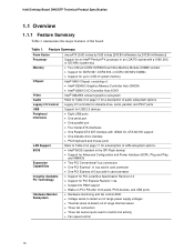
... Summary Form Factor microATX (9.60 inches by 9.60 inches [243.84 millimeters by 243.84 millimeters]) Processor Support for an Intel® Pentium® 4 processor in card connector Instantly Available PC Technology • Support for PCI Local Bus Specification Revision 2.3 •... Three fan connectors • Three fan sense inputs used to Table 2 on page 11 for a description of the board. Intel Desktop Board D945GTP Technical Product Specification 1.1 Overview 1.1.1 Feature Summary Table 1 summarizes the major features of audio subsystem options Legacy I/O Control Legacy ...
... Summary Form Factor microATX (9.60 inches by 9.60 inches [243.84 millimeters by 243.84 millimeters]) Processor Support for an Intel® Pentium® 4 processor in card connector Instantly Available PC Technology • Support for PCI Local Bus Specification Revision 2.3 •... Three fan connectors • Three fan sense inputs used to Table 2 on page 11 for a description of the board. Intel Desktop Board D945GTP Technical Product Specification 1.1 Overview 1.1.1 Feature Summary Table 1 summarizes the major features of audio subsystem options Legacy I/O Control Legacy ...
Product Specification
Page 14
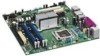
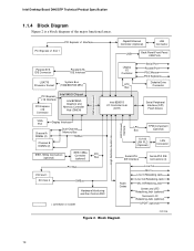
...Intel Desktop Board D945GTP Technical Product Specification 1.1.4 Block Diagram Figure 2 is a block diagram of the major functional areas. PCI Express x1 Interface PCI Express x1 Slot 1 Gigabit Ethernet Controller (Optional) LAN Connector USB Back Panel/Front Panel USB Ports Parallel ATA IDE Connector Parallel ATA IDE Interface LGA775 Processor... Socket System Bus (1066/800/533 MHz) PCI Express x16 Interface PCI Express x16 Connector Intel 945G Chipset Intel 82945G Graphics and Memory Controller Hub (GMCH) Legacy...
...Intel Desktop Board D945GTP Technical Product Specification 1.1.4 Block Diagram Figure 2 is a block diagram of the major functional areas. PCI Express x1 Interface PCI Express x1 Slot 1 Gigabit Ethernet Controller (Optional) LAN Connector USB Back Panel/Front Panel USB Ports Parallel ATA IDE Connector Parallel ATA IDE Interface LGA775 Processor... Socket System Bus (1066/800/533 MHz) PCI Express x16 Interface PCI Express x16 Connector Intel 945G Chipset Intel 82945G Graphics and Memory Controller Hub (GMCH) Legacy...

Product Specification
Page 15
...'S NOTE Use only ATX12V-compliant power supplies. Supported processors Refer to support Intel Pentium 4 processors in an LGA775 processor socket with a 1066, 800, or 533 MHz system bus. Product Description 1.2 Online Support To find information about... See the Intel web site listed below for the Desktop Board D945GTP Processor data sheets ICH7 addressing Custom splash screens Audio software...
...'S NOTE Use only ATX12V-compliant power supplies. Supported processors Refer to support Intel Pentium 4 processors in an LGA775 processor socket with a 1066, 800, or 533 MHz system bus. Product Description 1.2 Online Support To find information about... See the Intel web site listed below for the Desktop Board D945GTP Processor data sheets ICH7 addressing Custom splash screens Audio software...

Product Specification
Page 24
...installed on IDE bus allows host and target throttling. In legacy mode, standard IDE I /O (PIO): processor controls data transfer. • 8237-style DMA: DMA offloads the processor, supporting transfer rates of up to 16 MB/sec. • Ultra DMA: DMA protocol on IDE ... to reduce reflections, noise, and inductive coupling. One device can operate in both legacy and native modes. Intel Desktop Board D945GTP Technical Product Specification 1.5.3 IDE Support The board provides five IDE interface connectors: • One parallel ATA IDE connector that supports two devices • Four...
...installed on IDE bus allows host and target throttling. In legacy mode, standard IDE I /O (PIO): processor controls data transfer. • 8237-style DMA: DMA offloads the processor, supporting transfer rates of up to 16 MB/sec. • Ultra DMA: DMA protocol on IDE ... to reduce reflections, noise, and inductive coupling. One device can operate in both legacy and native modes. Intel Desktop Board D945GTP Technical Product Specification 1.5.3 IDE Support The board provides five IDE interface connectors: • One parallel ATA IDE connector that supports two devices • Four...

Product Specification
Page 35
...) NOTE Alter Standard Format (ASF) support is available only on boards that use the Intel 82573E Ethernet Controller or the Intel 82562GZ PLC device. The board has several hardware management features, including the following ASF support for PCI... Express x1 bus add-in LAN cards and PCI Conventional bus add-in LAN cards installed in PCI Conventional bus slot 2: • Monitoring of system firmware progress events, including: ⎯ BIOS present ⎯ Primary processor...
...) NOTE Alter Standard Format (ASF) support is available only on boards that use the Intel 82573E Ethernet Controller or the Intel 82562GZ PLC device. The board has several hardware management features, including the following ASF support for PCI... Express x1 bus add-in LAN cards and PCI Conventional bus add-in LAN cards installed in PCI Conventional bus slot 2: • Monitoring of system firmware progress events, including: ⎯ BIOS present ⎯ Primary processor...

Product Specification
Page 36
...to Figure 15, page 37 1.11.2 Chassis Intrusion and Detection The board supports a chassis security feature that detects if the chassis cover is in the closed -loop fan control, for direct monitoring of processor temperature and ambient temperature sensing • Power supply monitoring of five ...needed • SMBus interface For information about The functions of the fan connectors Refer to Section 1.12.2.2, page 41 36 Intel Desktop Board D945GTP Technical Product Specification 1.11.1 Hardware Monitoring and Fan Control ASIC The features of the hardware monitoring and fan control ASIC...
...to Figure 15, page 37 1.11.2 Chassis Intrusion and Detection The board supports a chassis security feature that detects if the chassis cover is in the closed -loop fan control, for direct monitoring of processor temperature and ambient temperature sensing • Power supply monitoring of five ...needed • SMBus interface For information about The functions of the fan connectors Refer to Section 1.12.2.2, page 41 36 Intel Desktop Board D945GTP Technical Product Specification 1.11.1 Hardware Monitoring and Fan Control ASIC The features of the hardware monitoring and fan control ASIC...
Product Specification
Page 37
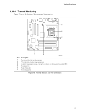
1.11.4 Thermal Monitoring Figure 15 shows the location of the sensors and fan connectors. Product Description 1 A 3 B C 4 1 D 13 Item A B C D E F F E OM17837 Description Remote ambient temperature sensor Thermal diode, located on processor die Ambient temperature sensor, internal to hardware monitoring and fan control ASIC Processor fan Rear chassis fan Front chassis fan Figure 15. Thermal Sensors and Fan Connectors 37
1.11.4 Thermal Monitoring Figure 15 shows the location of the sensors and fan connectors. Product Description 1 A 3 B C 4 1 D 13 Item A B C D E F F E OM17837 Description Remote ambient temperature sensor Thermal diode, located on processor die Ambient temperature sensor, internal to hardware monitoring and fan control ASIC Processor fan Rear chassis fan Front chassis fan Figure 15. Thermal Sensors and Fan Connectors 37

Product Specification
Page 39
...Description 1.12.1.1 System States and Power States Under ACPI, the operating system directs all system and device power state transitions. working state S0 - Processor stopped C1 - D3 - The operating system uses information from the computer. device specification specific. 5 W < power < 52.5 W G1 ...S4 (Suspend to the system. See the ACPI specification for appliances and personal computers. Full power > 30 W G1 - D3 - This board meets that are being used in S5 (Standby) mode. Suspend to RAM. No power D3 - working C0 - Suspend to disk. Context...
...Description 1.12.1.1 System States and Power States Under ACPI, the operating system directs all system and device power state transitions. working state S0 - Processor stopped C1 - D3 - The operating system uses information from the computer. device specification specific. 5 W < power < 52.5 W G1 ...S4 (Suspend to the system. See the ACPI specification for appliances and personal computers. Full power > 30 W G1 - D3 - This board meets that are being used in S5 (Standby) mode. Suspend to RAM. No power D3 - working C0 - Suspend to disk. Context...

Product Specification
Page 41
... failure, the computer returns to the power state it was in before power was interrupted (on when the board is in the S0 or S1 state. • The fans are off when the board is off or in the BIOS Setup program's Boot menu. When an ACPI-enabled system receives the correct.... For information about The location of the fan connectors The location of the fan connectors and sensors for thermal monitoring The signal names of the processor fan connector The signal names of the hardware monitoring and fan control ASIC. • All fan connectors support closed-loop fan control that provides full...
... failure, the computer returns to the power state it was in before power was interrupted (on when the board is in the S0 or S1 state. • The fans are off when the board is off or in the BIOS Setup program's Boot menu. When an ACPI-enabled system receives the correct.... For information about The location of the fan connectors The location of the fan connectors and sensors for thermal monitoring The signal names of the processor fan connector The signal names of the hardware monitoring and fan control ASIC. • All fan connectors support closed-loop fan control that provides full...

Product Specification
Page 59
Front and Rear Chassis Fan Connectors Pin Signal Name 1 FAN_CONTROL 2 +12 V 3 FAN_TACH Technical Reference 59 Processor Fan Connector Pin Signal Name 1 Ground 2 +12 V 3 FAN_TACH 4 FAN_CONTROL Table 24. Table 23.
Front and Rear Chassis Fan Connectors Pin Signal Name 1 FAN_CONTROL 2 +12 V 3 FAN_TACH Technical Reference 59 Processor Fan Connector Pin Signal Name 1 Ground 2 +12 V 3 FAN_TACH 4 FAN_CONTROL Table 24. Table 23.
Product Specification
Page 60
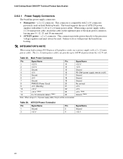
... the use a power supply with a 2 x 10 main power cable, attach that cable on Intel Desktop boards. Intel Desktop Board D945GTP Technical Product Specification 2.8.2.1 Power Supply Connectors The board has power supply connectors: • Main power - Table 26. When using high wattage PCI Express x16 graphics cards, use of power from the +12 V rail....12 V 60 Failure to 144 W of ATX12V power supplies with 2 x 10 connectors previously used . a 2 x 12 connector. This connector provides power directly to the processor voltage regulator and must always be unconnected.
... the use a power supply with a 2 x 10 main power cable, attach that cable on Intel Desktop boards. Intel Desktop Board D945GTP Technical Product Specification 2.8.2.1 Power Supply Connectors The board has power supply connectors: • Main power - Table 26. When using high wattage PCI Express x16 graphics cards, use of power from the +12 V rail....12 V 60 Failure to 144 W of ATX12V power supplies with 2 x 10 connectors previously used . a 2 x 12 connector. This connector provides power directly to the processor voltage regulator and must always be unconnected.
Product Specification
Page 65
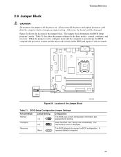
... the jumper block. A 1 recovery diskette is displayed. Recovery None 3 The BIOS attempts to configure mode and the computer is powered-up, the BIOS compares the processor version and the microcode version in the BIOS and reports if the two match. 31 J7J3 Figure 24. Technical Reference 2.9 Jumper Block CAUTION Do not.... The 1 maintenance menu is required. 65 Always turn off the power and unplug the power cord from the computer before changing a jumper setting. Otherwise, the board could be damaged. When the jumper is set to recover the BIOS configuration.
... the jumper block. A 1 recovery diskette is displayed. Recovery None 3 The BIOS attempts to configure mode and the computer is powered-up, the BIOS compares the processor version and the microcode version in the BIOS and reports if the two match. 31 J7J3 Figure 24. Technical Reference 2.9 Jumper Block CAUTION Do not.... The 1 maintenance menu is required. 65 Always turn off the power and unplug the power cord from the computer before changing a jumper setting. Otherwise, the board could be damaged. When the jumper is set to recover the BIOS configuration.
Product Specification
Page 69
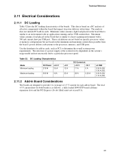
... draw for each add-in board. This data is based on the board that impact its power delivery subsystems. The analysis does not include PCI add-in cards. The selection of the boards. These calculations are not based on specific processor values or memory configurations but ...overall system power requirements. Minimum values assume a light load placed on the board that is dependent on the minimum and maximum current draw possible from the board's power delivery subsystems to a particular processor speed. Table 32. Technical Reference 2.11 Electrical Considerations 2.11.1 DC ...
... draw for each add-in board. This data is based on the board that impact its power delivery subsystems. The analysis does not include PCI add-in cards. The selection of the boards. These calculations are not based on specific processor values or memory configurations but ...overall system power requirements. Minimum values assume a light load placed on the board that is dependent on the minimum and maximum current draw possible from the board's power delivery subsystems to a particular processor speed. Table 32. Technical Reference 2.11 Electrical Considerations 2.11.1 DC ...
Product Specification
Page 70
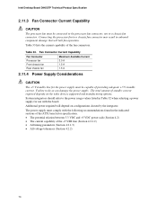
... with the following recommendations found in onboard component damage that will depend on the wake devices supported and manufacturing options. Intel Desktop Board D945GTP Technical Product Specification 2.11.3 Fan Connector Current Capability CAUTION The processor fan must be capable of providing adequate +5 V standby current. The total amount of the fan connectors. Failure to a chassis...
... with the following recommendations found in onboard component damage that will depend on the wake devices supported and manufacturing options. Intel Desktop Board D945GTP Technical Product Specification 2.11.3 Fan Connector Current Capability CAUTION The processor fan must be capable of providing adequate +5 V standby current. The total amount of the fan connectors. Failure to a chassis...

Product Specification
Page 71
...Processor Heatsink for determining the adequacy of any thermal or system design remains solely with Intel desktop boards please refer to the following the instructions presented in this document will result in a system with a maximum internal ambient temperature of chassis that merely following website: http://developer.intel... Failure to ensure appropriate airflow may result in reduced performance of both the processor and/or voltage regulator or, in some instances, damage to the board. Intel makes no warranties or representations that have been tested with the reader. CAUTION...
...Processor Heatsink for determining the adequacy of any thermal or system design remains solely with Intel desktop boards please refer to the following the instructions presented in this document will result in a system with a maximum internal ambient temperature of chassis that merely following website: http://developer.intel... Failure to ensure appropriate airflow may result in reduced performance of both the processor and/or voltage regulator or, in some instances, damage to the board. Intel makes no warranties or representations that have been tested with the reader. CAUTION...
Product Specification
Page 72
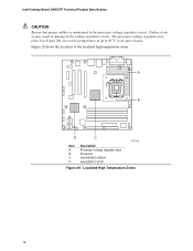
A B D C OM17842 Item A B C D Description Processor voltage regulator area Processor Intel 82945G GMCH Intel 82801G ICH7 Figure 29. Localized High Temperature Zones 72 Intel Desktop Board D945GTP Technical Product Specification CAUTION Ensure that proper airflow is maintained in damage to the voltage regulator circuit. Failure to 85 oC in Figure 29) ...
A B D C OM17842 Item A B C D Description Processor voltage regulator area Processor Intel 82945G GMCH Intel 82801G ICH7 Figure 29. Localized High Temperature Zones 72 Intel Desktop Board D945GTP Technical Product Specification CAUTION Ensure that proper airflow is maintained in damage to the voltage regulator circuit. Failure to 85 oC in Figure 29) ...


