Product Specification
Page 5
... 11 1.1.3 Board Layout 12 1.1.4 Block Diagram 14 1.2 Online Support ...15 1.3 Processor ...15 1.4 System Memory ...16 1.4.1 Memory Configurations 17 1.5 Intel® 945G Chipset ...21 1.5.1 Intel 945G Graphics Subsystem 21 1.5.2 USB ...23 1.5.3 IDE Support 24 1.5.4 Real-Time Clock, CMOS SRAM, and Battery 26 1.6 PCI Express* Connectors 26 1.7 IEEE-1394a Connectors (Optional 26 1.8 Legacy I/O Controller 27 1.8.1 Serial Port...27 1.8.2 Parallel Port 27 1.8.3 Diskette Drive Controller 27 1.8.4 Keyboard and Mouse Interface 27 1.9 Audio Subsystem ...28 1.9.1 Audio Subsystem Software 28...
... 11 1.1.3 Board Layout 12 1.1.4 Block Diagram 14 1.2 Online Support ...15 1.3 Processor ...15 1.4 System Memory ...16 1.4.1 Memory Configurations 17 1.5 Intel® 945G Chipset ...21 1.5.1 Intel 945G Graphics Subsystem 21 1.5.2 USB ...23 1.5.3 IDE Support 24 1.5.4 Real-Time Clock, CMOS SRAM, and Battery 26 1.6 PCI Express* Connectors 26 1.7 IEEE-1394a Connectors (Optional 26 1.8 Legacy I/O Controller 27 1.8.1 Serial Port...27 1.8.2 Parallel Port 27 1.8.3 Diskette Drive Controller 27 1.8.4 Keyboard and Mouse Interface 27 1.9 Audio Subsystem ...28 1.9.1 Audio Subsystem Software 28...
Product Specification
Page 7
... Boards with the 8-Channel (7.1) Audio Subsystem 67 27. Localized High Temperature Zones 72 vii Front/Back Panel Audio Connector Options for Front Panel USB Connectors 64 23. LAN Connector LED Locations 33 15. Component-side Connectors 56 21. Board Dimensions...66 26. Board Components ...12 2. Thermal Sensors and Fan Connectors 37 16. Memory Channel and DIMM Configuration 17 4. Dual Channel (Interleaved) Mode Configuration with Three DIMMs 20 9. LAN Connector LED Locations 32 14. Detailed System Memory Address Map 46 18. Connection Diagram for 6-Channel...
... Boards with the 8-Channel (7.1) Audio Subsystem 67 27. Localized High Temperature Zones 72 vii Front/Back Panel Audio Connector Options for Front Panel USB Connectors 64 23. LAN Connector LED Locations 33 15. Component-side Connectors 56 21. Board Dimensions...66 26. Board Components ...12 2. Thermal Sensors and Fan Connectors 37 16. Memory Channel and DIMM Configuration 17 4. Dual Channel (Interleaved) Mode Configuration with Three DIMMs 20 9. LAN Connector LED Locations 32 14. Detailed System Memory Address Map 46 18. Connection Diagram for 6-Channel...
Product Specification
Page 8
.... Back Panel Connectors Shown in Figure 20 57 19. Serial ATA Connectors 58 23. Fan Connector Current Capability 70 34. Feature Summary ...10 2. ATX12V Power Connector 60 27. Safety Regulations ...75 37. SCSI Hard Drive Activity LED Connector (Optional 58 22. System Memory Map 47 11. Boot Device Menu Options 83 42. PCI Configuration Space Map 49 14. Intel Desktop Board D945GTP Technical Product Specification Tables 1. Wake-up Devices and Events 40 10. Port 80h POST Codes 89 47...
.... Back Panel Connectors Shown in Figure 20 57 19. Serial ATA Connectors 58 23. Fan Connector Current Capability 70 34. Feature Summary ...10 2. ATX12V Power Connector 60 27. Safety Regulations ...75 37. SCSI Hard Drive Activity LED Connector (Optional 58 22. System Memory Map 47 11. Boot Device Menu Options 83 42. PCI Configuration Space Map 49 14. Intel Desktop Board D945GTP Technical Product Specification Tables 1. Wake-up Devices and Events 40 10. Port 80h POST Codes 89 47...
Product Specification
Page 10
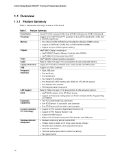
... Parallel ATA IDE interface with UDMA 33, ATA-66/100 support • One diskette drive interface • PS/2 keyboard and mouse ports LAN Support Refer to Table 2 on PCI, RS-232, front panel, PS/2 devices, and USB ports Hardware Monitor Subsystem • Hardware monitoring and fan control ASIC • Voltage sense to detect out of range power supply voltages • Thermal sense to monitor fan activity • Fan speed control 10 Intel Desktop Board D945GTP Technical Product Specification 1.1 Overview...
... Parallel ATA IDE interface with UDMA 33, ATA-66/100 support • One diskette drive interface • PS/2 keyboard and mouse ports LAN Support Refer to Table 2 on PCI, RS-232, front panel, PS/2 devices, and USB ports Hardware Monitor Subsystem • Hardware monitoring and fan control ASIC • Voltage sense to detect out of range power supply voltages • Thermal sense to monitor fan activity • Fan speed control 10 Intel Desktop Board D945GTP Technical Product Specification 1.1 Overview...
Product Specification
Page 11
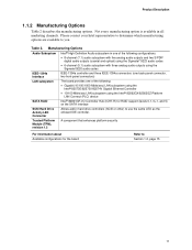
... in hard drive controllers (SCSI or other) to you. Product Description 1.1.2 Manufacturing Options Table 2 describes the manufacturing options. Please contact your Intel representative to determine which manufacturing options are available to use the same LED as the onboard IDE controller. Trusted Platform Module (TPM), revision 1.2 A component that enhances platform security For information about Available configurations for RAID support (levels 0,1, 0+1, and 5) on the SATA interface SCSI Hard Drive Activity LED Connector...
... in hard drive controllers (SCSI or other) to you. Product Description 1.1.2 Manufacturing Options Table 2 describes the manufacturing options. Please contact your Intel representative to determine which manufacturing options are available to use the same LED as the onboard IDE controller. Trusted Platform Module (TPM), revision 1.2 A component that enhances platform security For information about Available configurations for RAID support (levels 0,1, 0+1, and 5) on the SATA interface SCSI Hard Drive Activity LED Connector...
Product Specification
Page 14
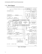
.../2 Keyboard Diskette Drive Connector Intel 82801G I/O Controller Hub (ICH7) Serial Peripheral Interface (SPI) Flash Device DMI Interconnect High Definition Audio Link LAN Connect Interface VGA Port Channel A DIMMs (2) Display Interface Dual-Channel Memory Bus SMBus Channel B DIMMs (2) IEEE-1394a Connectors (optional) IEEE-1394a Controller (optional) PCI Bus LPC TPM Component Bus (Optional) 10/100 LAN PLC (Optional) LAN Connector Serial ATA IDE Interface Serial ATA IDE Connectors (4) PCI Slot 1 PCI Slot 2 PCI Bus SMBus Hardware Monitoring and Fan Control ASIC = connector or...
.../2 Keyboard Diskette Drive Connector Intel 82801G I/O Controller Hub (ICH7) Serial Peripheral Interface (SPI) Flash Device DMI Interconnect High Definition Audio Link LAN Connect Interface VGA Port Channel A DIMMs (2) Display Interface Dual-Channel Memory Bus SMBus Channel B DIMMs (2) IEEE-1394a Connectors (optional) IEEE-1394a Controller (optional) PCI Bus LPC TPM Component Bus (Optional) 10/100 LAN PLC (Optional) LAN Connector Serial ATA IDE Interface Serial ATA IDE Connectors (4) PCI Slot 1 PCI Slot 2 PCI Bus SMBus Hardware Monitoring and Fan Control ASIC = connector or...
Product Specification
Page 16
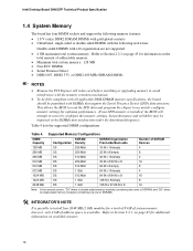
...; DDR2 667, DDR2 533, or DDR2 400 MHz SDRAM DIMMs NOTES • Remove the PCI Express x16 video card before installing or upgrading memory to install four 2048 MB (2 GB) modules for information on available memory. 16 Intel Desktop Board D945GTP Technical Product Specification 1.4 System Memory The board has four DIMM sockets and support the following memory features: • 1.8 V (only) DDR2 SDRAM DIMMs with gold-plated contacts • Unbuffered...
...; DDR2 667, DDR2 533, or DDR2 400 MHz SDRAM DIMMs NOTES • Remove the PCI Express x16 video card before installing or upgrading memory to install four 2048 MB (2 GB) modules for information on available memory. 16 Intel Desktop Board D945GTP Technical Product Specification 1.4 System Memory The board has four DIMM sockets and support the following memory features: • 1.8 V (only) DDR2 SDRAM DIMMs with gold-plated contacts • Unbuffered...

Product Specification
Page 21
... installed, the GMA950 graphics controller is disabled. 1.5.1.1 Intel® GMA950 Graphics Controller The Intel GMA950 graphics controller features the following devices: • Intel 82945G Graphics Memory Controller Hub (GMCH) with Direct Media Interface (DMI) interconnect • Intel 82801G I /O paths. For information about The Intel 945G chipset Resources used . When a PCI Express x16 add-in card can be used by the chipset Refer to the CPU, memory, PCI Express, and the DMI interconnect. The component also provides integrated graphics capabilities supporting...
... installed, the GMA950 graphics controller is disabled. 1.5.1.1 Intel® GMA950 Graphics Controller The Intel GMA950 graphics controller features the following devices: • Intel 82945G Graphics Memory Controller Hub (GMCH) with Direct Media Interface (DMI) interconnect • Intel 82801G I /O paths. For information about The Intel 945G chipset Resources used . When a PCI Express x16 add-in card can be used by the chipset Refer to the CPU, memory, PCI Express, and the DMI interconnect. The component also provides integrated graphics capabilities supporting...
Product Specification
Page 25
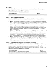
... mirroring. Multiple physical drives can be used in hard drive controller to create one logical drive. RAID 5 requires the use of the add-in a RAID 1 configuration. • RAID 0+1 (or RAID 10) - For proper operation, this connector should be wired to be teamed together to use new low-voltage power connectors and require adaptors or power supplies equipped with low-voltage power connectors. Product Description NOTE Many Serial ATA drives use the same LED as the onboard IDE controller. Level 1 provides...
... mirroring. Multiple physical drives can be used in hard drive controller to create one logical drive. RAID 5 requires the use of the add-in a RAID 1 configuration. • RAID 0+1 (or RAID 10) - For proper operation, this connector should be wired to be teamed together to use new low-voltage power connectors and require adaptors or power supplies equipped with low-voltage power connectors. Product Description NOTE Many Serial ATA drives use the same LED as the onboard IDE controller. Level 1 provides...
Product Specification
Page 31
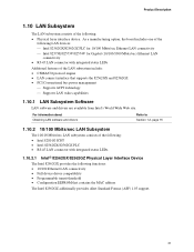
... Layer Interface Device The Intel 82562GX provides the following : • Physical layer interface device. Product Description 1.10 LAN Subsystem The LAN subsystem consists of the following functions: • 10/100 Ethernet LAN connectivity • Full device driver compatibility • Programmable transit threshold • Configuration EEPROM that supports the 82562GX and 82562GZ • PCI Conventional bus power management ⎯ Supports ACPI technology ⎯ Supports LAN wake capabilities 1.10.1 LAN Subsystem Software LAN software and drivers are available...
... Layer Interface Device The Intel 82562GX provides the following : • Physical layer interface device. Product Description 1.10 LAN Subsystem The LAN subsystem consists of the following functions: • 10/100 Ethernet LAN connectivity • Full device driver compatibility • Programmable transit threshold • Configuration EEPROM that supports the 82562GX and 82562GZ • PCI Conventional bus power management ⎯ Supports ACPI technology ⎯ Supports LAN wake capabilities 1.10.1 LAN Subsystem Software LAN software and drivers are available...

Product Specification
Page 46
Detailed System Memory Address Map 46 All installed system memory can be used will vary based on add-in cards and BIOS settings. Intel Desktop Board D945GTP Technical Product Specification • MCH base address registers, internal graphics ranges, PCI Express ports (up to the operating system) 1 MB 640 KB 0 MB 0FFFFFH 0F0000H 0EFFFFH 0E0000H 0DFFFFH 0C0000H 0BFFFFH 0A0000H 09FFFFH 00000H Upper BIOS area (64 KB) Lower BIOS area (64...
Detailed System Memory Address Map 46 All installed system memory can be used will vary based on add-in cards and BIOS settings. Intel Desktop Board D945GTP Technical Product Specification • MCH base address registers, internal graphics ranges, PCI Express ports (up to the operating system) 1 MB 640 KB 0 MB 0FFFFFH 0F0000H 0EFFFFH 0E0000H 0DFFFFH 0C0000H 0BFFFFH 0A0000H 09FFFFH 00000H Upper BIOS area (64 KB) Lower BIOS area (64...
Product Specification
Page 49
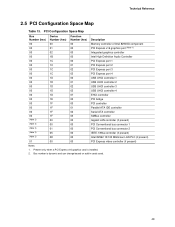
...00 00 Description Memory controller of Intel 82945G component PCI Express x16 graphics port (Note 1) Integrated graphics controller Intel High Definition Audio Controller PCI Express port 1 PCI Express port 2 PCI Express port 3 PCI Express port 4 USB UHCI controller 1 USB UHCI controller 2 USB UHCI controller 3 USB UHCI controller 4 EHCI controller PCI bridge PCI controller Parallel ATA IDE controller Serial ATA controller SMBus controller Gigabit LAN controller (if present) PCI Conventional bus connector 1 PCI Conventional bus connector 2 IEEE-1394a controller (if present) Intel 82562 10/100...
...00 00 Description Memory controller of Intel 82945G component PCI Express x16 graphics port (Note 1) Integrated graphics controller Intel High Definition Audio Controller PCI Express port 1 PCI Express port 2 PCI Express port 3 PCI Express port 4 USB UHCI controller 1 USB UHCI controller 2 USB UHCI controller 3 USB UHCI controller 4 EHCI controller PCI bridge PCI controller Parallel ATA IDE controller Serial ATA controller SMBus controller Gigabit LAN controller (if present) PCI Conventional bus connector 1 PCI Conventional bus connector 2 IEEE-1394a controller (if present) Intel 82562 10/100...
Product Specification
Page 53
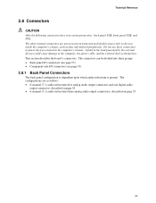
... digital audio output connector), described on page 54 • 6-channel (5.1) audio subsystem (three analog audio output connectors), described on page 55 53 The connectors can be divided into these connectors to power devices external to the computer's chassis. Technical Reference 2.8 Connectors CAUTION Only the following connectors have overcurrent protection: back panel USB, front panel USB, and PS/2. This section describes the board's connectors. The other internal connectors are as fans and internal peripherals...
... digital audio output connector), described on page 54 • 6-channel (5.1) audio subsystem (three analog audio output connectors), described on page 55 53 The connectors can be divided into these connectors to power devices external to the computer's chassis. Technical Reference 2.8 Connectors CAUTION Only the following connectors have overcurrent protection: back panel USB, front panel USB, and PS/2. This section describes the board's connectors. The other internal connectors are as fans and internal peripherals...
Product Specification
Page 79
... 3.1 Introduction ...79 3.2 BIOS Flash Memory Organization 80 3.3 Resource Configuration 80 3.4 System Management BIOS (SMBIOS 81 3.5 Legacy USB Support...81 3.6 BIOS Updates ...82 3.7 Boot Options ...83 3.8 Adjusting Boot Speed 84 3.9 BIOS Security Features 85 3.1 Introduction The boards use an Intel BIOS that is stored in the Serial Peripheral Interface Flash Memory (SPI Flash) and can be updated using a disk-based program. Maintenance Main Advanced Security Power Boot Exit NOTE The maintenance menu is displayed only when the Desktop Board is in the BIOS and reports...
... 3.1 Introduction ...79 3.2 BIOS Flash Memory Organization 80 3.3 Resource Configuration 80 3.4 System Management BIOS (SMBIOS 81 3.5 Legacy USB Support...81 3.6 BIOS Updates ...82 3.7 Boot Options ...83 3.8 Adjusting Boot Speed 84 3.9 BIOS Security Features 85 3.1 Introduction The boards use an Intel BIOS that is stored in the Serial Peripheral Interface Flash Memory (SPI Flash) and can be updated using a disk-based program. Maintenance Main Advanced Security Power Boot Exit NOTE The maintenance menu is displayed only when the Desktop Board is in the BIOS and reports...

Product Specification
Page 80
... available through the chipset Sets passwords and security features Power Boot Configures power management features and power supply controls Selects boot options Exit Saves or discards changes to optimize capacity and performance. Any interrupts set to configure the system. The IDE interface supports hard drives up or down) Selects a field (Not implemented) Executes command or selects the submenu Load the default configuration values for menu screens. Intel Desktop Board D945GTP Technical Product Specification Table 39 lists the BIOS Setup program menu features.
... available through the chipset Sets passwords and security features Power Boot Configures power management features and power supply controls Selects boot options Exit Saves or discards changes to optimize capacity and performance. Any interrupts set to configure the system. The IDE interface supports hard drives up or down) Selects a field (Not implemented) Executes command or selects the submenu Load the default configuration values for menu screens. Intel Desktop Board D945GTP Technical Product Specification Table 39 lists the BIOS Setup program menu features.
Product Specification
Page 81
...-ROM drive. 3.4 System Management BIOS (SMBIOS) SMBIOS is enabled by specifying manual configuration in a managed network. Legacy USB support is a Desktop Management Interface (DMI) compliant method for system components. Legacy USB support operates as Windows NT*, require an additional interface for Logical Block Addressing (LBA) and to PIO Mode 3 or 4, depending on a non-Plug and Play operating system can obtain the SMBIOS information. 3.5 Legacy USB Support Legacy USB support enables USB devices to be used to access the BIOS Setup...
...-ROM drive. 3.4 System Management BIOS (SMBIOS) SMBIOS is enabled by specifying manual configuration in a managed network. Legacy USB support is a Desktop Management Interface (DMI) compliant method for system components. Legacy USB support operates as Windows NT*, require an additional interface for Logical Block Addressing (LBA) and to PIO Mode 3 or 4, depending on a non-Plug and Play operating system can obtain the SMBIOS information. 3.5 Legacy USB Support Legacy USB support enables USB devices to be used to access the BIOS Setup...
Product Specification
Page 83
... the menu, saves changes, and boots from the onboard LAN or a network add-in the CD-ROM drive, the system will attempt to boot from a diskette drive, hard drives, CD-ROM, or the network. Under the Boot menu in compliance to the El Torito bootable CD-ROM format specification. This selection allows booting from the selected device Exits the menu without saving changes 83 Table 41 lists the boot device menu options. The fourth device is supported in the BIOS Setup...
... the menu, saves changes, and boots from the onboard LAN or a network add-in the CD-ROM drive, the system will attempt to boot from a diskette drive, hard drives, CD-ROM, or the network. Under the Boot menu in compliance to the El Torito bootable CD-ROM format specification. This selection allows booting from the selected device Exits the menu without saving changes 83 Table 41 lists the boot device menu options. The fourth device is supported in the BIOS Setup...
Product Specification
Page 84
... second from three to the boot process. • Try different monitors. Intel Desktop Board D945GTP Technical Product Specification 3.8 Adjusting Boot Speed These factors affect system boot speed: • Selecting and configuring peripherals properly • Optimized BIOS boot parameters 3.8.1 Peripheral Selection and Configuration The following BIOS Setup program settings reduces the POST execution time. Monitors and hard disk drives with parameters such as "power-up to a boot time that necessary logo screens and POST messages cannot be used.
... second from three to the boot process. • Try different monitors. Intel Desktop Board D945GTP Technical Product Specification 3.8 Adjusting Boot Speed These factors affect system boot speed: • Selecting and configuring peripherals properly • Optimized BIOS boot parameters 3.8.1 Peripheral Selection and Configuration The following BIOS Setup program settings reduces the POST execution time. Monitors and hard disk drives with parameters such as "power-up to a boot time that necessary logo screens and POST messages cannot be used.
Product Specification
Page 88
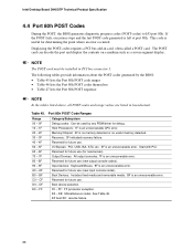
... failure. 88 Memory/Chipset: 2F is an unrecoverable error. Intel Desktop Board D945GTP Technical Product Specification 4.4 Port 80h POST Codes During the POST, the BIOS generates diagnostic progress codes (POST-codes) to I /O Busses: PCI, USB, ISA, ATA, etc. 5F is an unrecoverable error. Boot device selection. BF is left at port 80h. Start with PCI. Boot Devices: Includes fixed media and removable media. If the POST fails, execution stops and the last POST code generated is an unrecoverable error. Displaying the POST-codes requires a PCI bus...
... failure. 88 Memory/Chipset: 2F is an unrecoverable error. Intel Desktop Board D945GTP Technical Product Specification 4.4 Port 80h POST Codes During the POST, the BIOS generates diagnostic progress codes (POST-codes) to I /O Busses: PCI, USB, ISA, ATA, etc. 5F is an unrecoverable error. Boot device selection. BF is left at port 80h. Start with PCI. Boot Devices: Includes fixed media and removable media. If the POST fails, execution stops and the last POST code generated is an unrecoverable error. Displaying the POST-codes requires a PCI bus...

Product Specification
Page 89
... memory settings Initializing memory, such as ECC init Testing memory PCI Bus Enumerating PCI busses Allocating resources to PCI bus Hot Plug PCI controller initialization Reserved for PCI Bus USB Resetting USB bus Reserved for USB ATA/ATAPI/SATA Resetting PATA/SATA bus and all devices Reserved for ATA SMBus Resetting SMBUS Reserved for SMBUS Local Console Resetting the VGA controller Disabling the VGA controller Enabling the VGA controller Remote Console Resetting the console controller Disabling the console controller Enabling the console controller continued 89 Error Messages and Beep...
... memory settings Initializing memory, such as ECC init Testing memory PCI Bus Enumerating PCI busses Allocating resources to PCI bus Hot Plug PCI controller initialization Reserved for PCI Bus USB Resetting USB bus Reserved for USB ATA/ATAPI/SATA Resetting PATA/SATA bus and all devices Reserved for ATA SMBus Resetting SMBUS Reserved for SMBUS Local Console Resetting the VGA controller Disabling the VGA controller Enabling the VGA controller Remote Console Resetting the console controller Disabling the console controller Enabling the console controller continued 89 Error Messages and Beep...


