Product Specification
Page 5
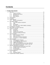
...Summary 10 1.1.2 Manufacturing Options 11 1.1.3 Board Layout 12 1.1.4 Block Diagram 14 1.2 Online Support ...15 1.3 Processor ...15 1.4 System Memory ...16 1.4.1 Memory Configurations 17 1.5 Intel® 945G Chipset ...21 1.5.1 Intel 945G Graphics Subsystem 21 1.5.2 USB ...23 1.5.3 IDE Support 24 1.5.4 Real-Time Clock, CMOS SRAM, and....1 LAN Subsystem Software 31 1.10.2 10/100 Mbits/sec LAN Subsystem 31 1.10.3 Gigabit LAN Subsystem 32 1.10.4 Intel® Active Management Technology (Optional 33 1.10.5 Alert Standard Format (ASF) Support (Optional 35 1.11 Hardware Management Subsystem...
...Summary 10 1.1.2 Manufacturing Options 11 1.1.3 Board Layout 12 1.1.4 Block Diagram 14 1.2 Online Support ...15 1.3 Processor ...15 1.4 System Memory ...16 1.4.1 Memory Configurations 17 1.5 Intel® 945G Chipset ...21 1.5.1 Intel 945G Graphics Subsystem 21 1.5.2 USB ...23 1.5.3 IDE Support 24 1.5.4 Real-Time Clock, CMOS SRAM, and....1 LAN Subsystem Software 31 1.10.2 10/100 Mbits/sec LAN Subsystem 31 1.10.3 Gigabit LAN Subsystem 32 1.10.4 Intel® Active Management Technology (Optional 33 1.10.5 Alert Standard Format (ASF) Support (Optional 35 1.11 Hardware Management Subsystem...
Product Specification
Page 7
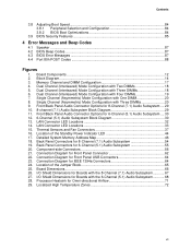
...-side Connectors 56 21. LAN Connector LED Locations 32 14. Connection Diagram for 8-Channel (7.1) Audio Subsystem .... 29 10. 8-channel (7.1) Audio Subsystem Block Diagram 29 11. Processor Heatsink for 6-Channel (5.1) Audio Subsystem .... 30 12. 6-Channel (5.1) Audio Subsystem Block Diagram 30 13. Location of the Jumper Block 65 25. Front/Back Panel Audio...
...-side Connectors 56 21. LAN Connector LED Locations 32 14. Connection Diagram for 8-Channel (7.1) Audio Subsystem .... 29 10. 8-channel (7.1) Audio Subsystem Block Diagram 29 11. Processor Heatsink for 6-Channel (5.1) Audio Subsystem .... 30 12. 6-Channel (5.1) Audio Subsystem Block Diagram 30 13. Location of the Jumper Block 65 25. Front/Back Panel Audio...
Product Specification
Page 8
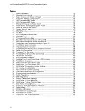
...Component-side Connectors Shown in Figure 19 55 18. SCSI Hard Drive Activity LED Connector (Optional 58 22. Serial ATA Connectors 58 23. Processor Fan Connector 59 24. Auxiliary Front Panel Power/Sleep LED Connector 61 28. Thermal Considerations for a Two-Color Power LED 63 31.... Summary ...10 2. ATX12V Power Connector 60 27. BIOS Setup Configuration Jumper Settings 65 32. BIOS Setup Program Function Keys 80 41. Intel Desktop Board D945GTP Technical Product Specification Tables 1. System Memory Map 47 11. Interrupts ...50 15. PCI Interrupt Routing Map 51 16. ...
...Component-side Connectors Shown in Figure 19 55 18. SCSI Hard Drive Activity LED Connector (Optional 58 22. Serial ATA Connectors 58 23. Processor Fan Connector 59 24. Auxiliary Front Panel Power/Sleep LED Connector 61 28. Thermal Considerations for a Two-Color Power LED 63 31.... Summary ...10 2. ATX12V Power Connector 60 27. BIOS Setup Configuration Jumper Settings 65 32. BIOS Setup Program Function Keys 80 41. Intel Desktop Board D945GTP Technical Product Specification Tables 1. System Memory Map 47 11. Interrupts ...50 15. PCI Interrupt Routing Map 51 16. ...
Product Specification
Page 9
1 Product Description What This Chapter Contains 1.1 Overview ...10 1.2 Online Support ...15 1.3 Processor ...15 1.4 System Memory ...16 1.5 Intel® 945G Chipset ...21 1.6 PCI Express* Connectors 26 1.7 IEEE-1394a Connectors (Optional 26 1.8 Legacy I/O Controller 27 1.9 Audio Subsystem ...28 1.10 LAN Subsystem ...31 1.11 Hardware Management Subsystem 35 1.12 Power Management ...38 1.13 Trusted Platform Module (Optional 44 9
1 Product Description What This Chapter Contains 1.1 Overview ...10 1.2 Online Support ...15 1.3 Processor ...15 1.4 System Memory ...16 1.5 Intel® 945G Chipset ...21 1.6 PCI Express* Connectors 26 1.7 IEEE-1394a Connectors (Optional 26 1.8 Legacy I/O Controller 27 1.9 Audio Subsystem ...28 1.10 LAN Subsystem ...31 1.11 Hardware Management Subsystem 35 1.12 Power Management ...38 1.13 Trusted Platform Module (Optional 44 9
Product Specification
Page 10
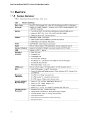
... • Fan speed control 10 Feature Summary Form Factor microATX (9.60 inches by 9.60 inches [243.84 millimeters by 243.84 millimeters]) Processor Support for an Intel® Pentium® 4 processor in card connector Instantly Available PC Technology • Support for PCI Local Bus Specification Revision 2.3 • Support for a description of LAN subsystem...
... • Fan speed control 10 Feature Summary Form Factor microATX (9.60 inches by 9.60 inches [243.84 millimeters by 243.84 millimeters]) Processor Support for an Intel® Pentium® 4 processor in card connector Instantly Available PC Technology • Support for PCI Local Bus Specification Revision 2.3 • Support for a description of LAN subsystem...
Product Specification
Page 14
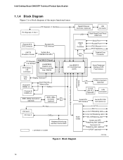
.../Front Panel USB Ports Parallel ATA IDE Connector Parallel ATA IDE Interface LGA775 Processor Socket System Bus (1066/800/533 MHz) PCI Express x16 Interface PCI Express x16 Connector Intel 945G Chipset Intel 82945G Graphics and Memory Controller Hub (GMCH) Legacy I/O Controller LPC Bus ...Serial Port Parallel Port PS/2 Mouse PS/2 Keyboard Diskette Drive Connector Intel 82801G I/O Controller Hub (ICH7) Serial Peripheral Interface (SPI) Flash Device DMI Interconnect High Definition Audio Link LAN Connect Interface VGA ...
.../Front Panel USB Ports Parallel ATA IDE Connector Parallel ATA IDE Interface LGA775 Processor Socket System Bus (1066/800/533 MHz) PCI Express x16 Interface PCI Express x16 Connector Intel 945G Chipset Intel 82945G Graphics and Memory Controller Hub (GMCH) Legacy I/O Controller LPC Bus ...Serial Port Parallel Port PS/2 Mouse PS/2 Keyboard Diskette Drive Connector Intel 82801G I/O Controller Hub (ICH7) Serial Peripheral Interface (SPI) Flash Device DMI Interconnect High Definition Audio Link LAN Connect Interface VGA ...

Product Specification
Page 15
.../technology/manage/iamt/index.htm 1.3 Processor The board is designed to support Intel Pentium 4 processors in an LGA775 processor socket with a 1066, 800, or 533 MHz system bus. Product Description 1.2 Online Support To find information about Power supply connectors Refer to Section 2.8.2.1, page 60 15 Use of supported processors. Intel Desktop Board D945GTP under "Desktop Board...
.../technology/manage/iamt/index.htm 1.3 Processor The board is designed to support Intel Pentium 4 processors in an LGA775 processor socket with a 1066, 800, or 533 MHz system bus. Product Description 1.2 Online Support To find information about Power supply connectors Refer to Section 2.8.2.1, page 60 15 Use of supported processors. Intel Desktop Board D945GTP under "Desktop Board...

Product Specification
Page 24
...-66 and ATA-100 are assigned (IRQ 14 and 15). In legacy mode, standard IDE I /O (PIO): processor controls data transfer. • 8237-style DMA: DMA offloads the processor, supporting transfer rates of up to 16 MB/sec. • Ultra DMA: DMA protocol on IDE bus supporting ... and write transfer rates up to device connections, unlike Parallel ATA IDE which supports a master/slave configuration and two devices per channel. Intel Desktop Board D945GTP Technical Product Specification 1.5.3 IDE Support The board provides five IDE interface connectors: • One parallel ATA IDE connector that...
...-66 and ATA-100 are assigned (IRQ 14 and 15). In legacy mode, standard IDE I /O (PIO): processor controls data transfer. • 8237-style DMA: DMA offloads the processor, supporting transfer rates of up to 16 MB/sec. • Ultra DMA: DMA protocol on IDE bus supporting ... and write transfer rates up to device connections, unlike Parallel ATA IDE which supports a master/slave configuration and two devices per channel. Intel Desktop Board D945GTP Technical Product Specification 1.5.3 IDE Support The board provides five IDE interface connectors: • One parallel ATA IDE connector that...

Product Specification
Page 35
...Conventional bus add-in LAN cards installed in PCI Conventional bus slot 2: • Monitoring of system firmware progress events, including: ⎯ BIOS present ⎯ Primary processor initialization ⎯ Memory initialization ⎯ Video initialization ⎯ PCI resource configuration ⎯ Hard-disk initialization ⎯ User authentication ⎯ Starting operating system boot process...Product Description 1.10.5 Alert Standard Format (ASF) Support (Optional) NOTE Alter Standard Format (ASF) support is available only on boards that use the Intel 82573E Ethernet Controller or the...
...Conventional bus add-in LAN cards installed in PCI Conventional bus slot 2: • Monitoring of system firmware progress events, including: ⎯ BIOS present ⎯ Primary processor initialization ⎯ Memory initialization ⎯ Video initialization ⎯ PCI resource configuration ⎯ Hard-disk initialization ⎯ User authentication ⎯ Starting operating system boot process...Product Description 1.10.5 Alert Standard Format (ASF) Support (Optional) NOTE Alter Standard Format (ASF) support is available only on boards that use the Intel 82573E Ethernet Controller or the...

Product Specification
Page 36
... For information about The functions of monitoring and control is dependent on the hardware monitoring ASIC used with the board. Intel Desktop Board D945GTP Technical Product Specification 1.11.1 Hardware Monitoring and Fan Control ASIC The features of the hardware monitoring and... fan control ASIC include: • Internal ambient temperature sensor • Two remote thermal diode sensors for direct monitoring of processor temperature and ambient temperature sensing • Power supply monitoring of five voltages (+5 V, +12 V, +3.3 VSB, +1.5 V, and +VCCP) ...
... For information about The functions of monitoring and control is dependent on the hardware monitoring ASIC used with the board. Intel Desktop Board D945GTP Technical Product Specification 1.11.1 Hardware Monitoring and Fan Control ASIC The features of the hardware monitoring and... fan control ASIC include: • Internal ambient temperature sensor • Two remote thermal diode sensors for direct monitoring of processor temperature and ambient temperature sensing • Power supply monitoring of five voltages (+5 V, +12 V, +3.3 VSB, +1.5 V, and +VCCP) ...
Product Specification
Page 37
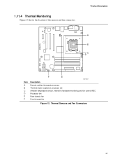
Thermal Sensors and Fan Connectors 37 Product Description 1 A 3 B C 4 1 D 13 Item A B C D E F F E OM17837 Description Remote ambient temperature sensor Thermal diode, located on processor die Ambient temperature sensor, internal to hardware monitoring and fan control ASIC Processor fan Rear chassis fan Front chassis fan Figure 15. 1.11.4 Thermal Monitoring Figure 15 shows the location of the sensors and fan connectors.
Thermal Sensors and Fan Connectors 37 Product Description 1 A 3 B C 4 1 D 13 Item A B C D E F F E OM17837 Description Remote ambient temperature sensor Thermal diode, located on processor die Ambient temperature sensor, internal to hardware monitoring and fan control ASIC Processor fan Rear chassis fan Front chassis fan Figure 15. 1.11.4 Thermal Monitoring Figure 15 shows the location of the sensors and fan connectors.

Product Specification
Page 39
Devices that requirement by battery or external source. Table 8. Power States and Targeted System Power Global States Sleeping States Processor States Device States Targeted System Power (Note 1) G0 - Full power > 30 W G1 - device specification specific. 5 W < power < 52.5 W G1 - ...power except for wake-up logic. Total system power is dependent on the standby power consumption of wake-up logic. sleeping state S1 - Processor stopped C1 - sleeping state G1 - S5 - no power except for wake-up devices used in boards and peripherals powered by the ...
Devices that requirement by battery or external source. Table 8. Power States and Targeted System Power Global States Sleeping States Processor States Device States Targeted System Power (Note 1) G0 - Full power > 30 W G1 - device specification specific. 5 W < power < 52.5 W G1 - ...power except for wake-up logic. Total system power is dependent on the standby power consumption of wake-up logic. sleeping state S1 - Processor stopped C1 - sleeping state G1 - S5 - no power except for wake-up devices used in boards and peripherals powered by the ...

Product Specification
Page 41
For information about The location of the fan connectors The location of the fan connectors and sensors for thermal monitoring The signal names of the processor fan connector The signal names of the chassis fan connectors Refer to Figure 20, page 56 Figure 15, page 37 Table 23, page 59 Table ...
For information about The location of the fan connectors The location of the fan connectors and sensors for thermal monitoring The signal names of the processor fan connector The signal names of the chassis fan connectors Refer to Figure 20, page 56 Figure 15, page 37 Table 23, page 59 Table ...

Product Specification
Page 59
Processor Fan Connector Pin Signal Name 1 Ground 2 +12 V 3 FAN_TACH 4 FAN_CONTROL Table 24. Front and Rear Chassis Fan Connectors Pin Signal Name 1 FAN_CONTROL 2 +12 V 3 FAN_TACH Technical Reference 59 Table 23.
Processor Fan Connector Pin Signal Name 1 Ground 2 +12 V 3 FAN_TACH 4 FAN_CONTROL Table 24. Front and Rear Chassis Fan Connectors Pin Signal Name 1 FAN_CONTROL 2 +12 V 3 FAN_TACH Technical Reference 59 Table 23.
Product Specification
Page 60
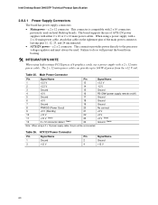
... supply with 2 x 10 connectors previously used . Table 25. The 2 x 12 main power cable can provide up to the processor voltage regulator and must always be unconnected. This connector provides power directly to 144 W of ATX12V power supplies with a 2 x 12... Signal Name 2 Ground 4 +12 V 60 This connector is compatible with a 2 x 10 main power cable, attach that cable on Intel Desktop boards. Intel Desktop Board D945GTP Technical Product Specification 2.8.2.1 Power Supply Connectors The board has power supply connectors: • Main power - a 2 x 12 connector. a...
... supply with 2 x 10 connectors previously used . Table 25. The 2 x 12 main power cable can provide up to the processor voltage regulator and must always be unconnected. This connector provides power directly to 144 W of ATX12V power supplies with a 2 x 12... Signal Name 2 Ground 4 +12 V 60 This connector is compatible with a 2 x 10 main power cable, attach that cable on Intel Desktop boards. Intel Desktop Board D945GTP Technical Product Specification 2.8.2.1 Power Supply Connectors The board has power supply connectors: • Main power - a 2 x 12 connector. a...
Product Specification
Page 65
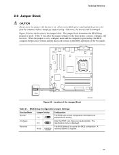
... determines the BIOS Setup program's mode. Location of the jumper block. A 1 recovery diskette is displayed. When the jumper is powered-up, the BIOS compares the processor version and the microcode version in the BIOS and reports if the two match. 31 J7J3 Figure 24. Configure 2-3 3 After the POST runs, Setup runs...
... determines the BIOS Setup program's mode. Location of the jumper block. A 1 recovery diskette is displayed. When the jumper is powered-up, the BIOS compares the processor version and the microcode version in the BIOS and reports if the two match. 31 J7J3 Figure 24. Configure 2-3 3 After the POST runs, Setup runs...
Product Specification
Page 69
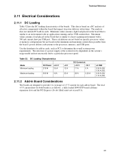
... Add-in board. The total +5 V current draw for each add-in Board Considerations The boards are based on the board that is similar to a particular processor speed. DC Loading Characteristics Mode Minimum loading Maximum loading DC Power +3.3 V 275 W 3.5 A 500 W 16 A +5 V 12 A 23 A DC Current... are designed to determine the overall system power requirements. These calculations are not based on the board that is similar to the processor, memory, and USB ports. Maximum values assume a load placed on the minimum and maximum current draw possible from the board's...
... Add-in board. The total +5 V current draw for each add-in Board Considerations The boards are based on the board that is similar to a particular processor speed. DC Loading Characteristics Mode Minimum loading Maximum loading DC Power +3.3 V 275 W 3.5 A 500 W 16 A +5 V 12 A 23 A DC Current... are designed to determine the overall system power requirements. These calculations are not based on the board that is similar to the processor, memory, and USB ports. Maximum values assume a load placed on the minimum and maximum current draw possible from the board's...
Product Specification
Page 70
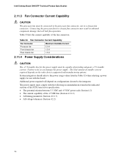
.... Additional power required will halt fan operation. Table 33 lists the current capability of the fan connectors. Fan Connector Current Capability Fan Connector Processor fan Front chassis fan Rear chassis fan Maximum Available Current 3.0 A 1.5 A 1.5 A 2.11.4 Power Supply Considerations CAUTION The +5 V...a power supply for the power supply must be connected to the processor fan connector, not to a chassis fan connector. Connecting the processor fan to do so can damage the power supply. Intel Desktop Board D945GTP Technical Product Specification 2.11.3 Fan Connector Current Capability...
.... Additional power required will halt fan operation. Table 33 lists the current capability of the fan connectors. Fan Connector Current Capability Fan Connector Processor fan Front chassis fan Rear chassis fan Maximum Available Current 3.0 A 1.5 A 1.5 A 2.11.4 Power Supply Considerations CAUTION The +5 V...a power supply for the power supply must be connected to the processor fan connector, not to a chassis fan connector. Connecting the processor fan to do so can damage the power supply. Intel Desktop Board D945GTP Technical Product Specification 2.11.3 Fan Connector Current Capability...

Product Specification
Page 71
... for Omni-directional Airflow CAUTION Failure to ensure appropriate airflow may result in a system with the reader. Intel makes no warranties or representations that have been tested with a maximum internal ambient temperature of both the processor and/or voltage regulator or, in Section 2.14. 71 For information about the maximum operating temperature...
... for Omni-directional Airflow CAUTION Failure to ensure appropriate airflow may result in a system with the reader. Intel makes no warranties or representations that have been tested with a maximum internal ambient temperature of both the processor and/or voltage regulator or, in Section 2.14. 71 For information about the maximum operating temperature...
Product Specification
Page 72
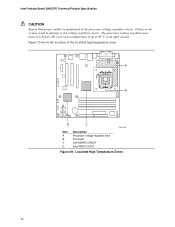
... A in Figure 29) can reach a temperature of the localized high temperature zones. A B D C OM17842 Item A B C D Description Processor voltage regulator area Processor Intel 82945G GMCH Intel 82801G ICH7 Figure 29. Localized High Temperature Zones 72 Failure to the voltage regulator circuit. Intel Desktop Board D945GTP Technical Product Specification CAUTION Ensure that proper airflow is maintained in the...
... A in Figure 29) can reach a temperature of the localized high temperature zones. A B D C OM17842 Item A B C D Description Processor voltage regulator area Processor Intel 82945G GMCH Intel 82801G ICH7 Figure 29. Localized High Temperature Zones 72 Failure to the voltage regulator circuit. Intel Desktop Board D945GTP Technical Product Specification CAUTION Ensure that proper airflow is maintained in the...


