
Product Guide
Page 3
... hardware components 3 Updating the BIOS: instructions on how to update the BIOS 4 Configuring for RAID (Intel® Matrix Storage Technology (Intel® MST)): information about configuring your system for RAID 5 Configuring for Intel® Rapid Recover Technology (Intel® RRT): information about configuring your system for Intel Rapid Recover Technology A Error Messages and Indicators: information about board layout, component installation, BIOS update, and regulatory requirements for installation in this Product Guide are arranged as follows: 1 Desktop Board Features: a summary...
... hardware components 3 Updating the BIOS: instructions on how to update the BIOS 4 Configuring for RAID (Intel® Matrix Storage Technology (Intel® MST)): information about configuring your system for RAID 5 Configuring for Intel® Rapid Recover Technology (Intel® RRT): information about configuring your system for Intel Rapid Recover Technology A Error Messages and Indicators: information about board layout, component installation, BIOS update, and regulatory requirements for installation in this Product Guide are arranged as follows: 1 Desktop Board Features: a summary...

Product Guide
Page 5
...DVI-I Support 15 HDMI* Technology Support 15 PCI Express x16 Graphics 16 Intel® Viiv™ Technology 16 Audio Subsystem 16 Legacy Input/Output (I/O) Controller 17 LAN Subsystem 17 LAN Subsystem Software 17 LAN Status Indicators 18 Hi-Speed USB 2.0 Support 18 Serial ATA...19 Serial ATA RAID 19 Intel® Rapid Recover Technology (Intel® RRT 19 Expandability...19 BIOS ...20 Serial ATA Auto Configuration 20 PCI and PCI Express* Auto Configuration 20 Security Passwords 20 Hardware Management Features 21 Fan Speed, Thermal, and Voltage Monitoring and Control 21 Chassis...
...DVI-I Support 15 HDMI* Technology Support 15 PCI Express x16 Graphics 16 Intel® Viiv™ Technology 16 Audio Subsystem 16 Legacy Input/Output (I/O) Controller 17 LAN Subsystem 17 LAN Subsystem Software 17 LAN Status Indicators 18 Hi-Speed USB 2.0 Support 18 Serial ATA...19 Serial ATA RAID 19 Intel® Rapid Recover Technology (Intel® RRT 19 Expandability...19 BIOS ...20 Serial ATA Auto Configuration 20 PCI and PCI Express* Auto Configuration 20 Security Passwords 20 Hardware Management Features 21 Fan Speed, Thermal, and Voltage Monitoring and Control 21 Chassis...

Product Guide
Page 6
...PCI Express x16 Card 42 Connecting Serial ATA (SATA) Cables 43 Connecting to Internal Headers and Connectors 44 HD Audio Link Header 45 S/PDIF Connector 45 Front Panel HD Audio Header 45 Consumer IR (CIR) Headers 46 Serial Port Header 47 Chassis Intrusion Header 47 Alternate Front Panel Power LED Header 47 Front Panel Header 48 USB 2.0 Headers 48 IEEE 1394a Header 49 Connecting to the Audio System 49 Connecting Chassis Fan and Power Supply Cables 50 Chassis Fan Cables 50 Power Supply Cables 51 Setting the BIOS Configuration Jumper 52 Clearing Passwords 53 3 Updating the BIOS...
...PCI Express x16 Card 42 Connecting Serial ATA (SATA) Cables 43 Connecting to Internal Headers and Connectors 44 HD Audio Link Header 45 S/PDIF Connector 45 Front Panel HD Audio Header 45 Consumer IR (CIR) Headers 46 Serial Port Header 47 Chassis Intrusion Header 47 Alternate Front Panel Power LED Header 47 Front Panel Header 48 USB 2.0 Headers 48 IEEE 1394a Header 49 Connecting to the Audio System 49 Connecting Chassis Fan and Power Supply Cables 50 Chassis Fan Cables 50 Power Supply Cables 51 Setting the BIOS Configuration Jumper 52 Clearing Passwords 53 3 Updating the BIOS...

Product Guide
Page 7
... Your RAID Set 65 Loading the Intel Matrix Storage Technology RAID Drivers and Software 66 Setting Up a "RAID Ready" System 66 5 Configuring for Intel® Rapid Recover Technology 67 Enabling Intel Rapid Recover Technology 67 Creating a Recovery Volume 68 Creating a Recovery Volume Using the RAID Option ROM 68 Creating a Recovery Volume Using the Intel Matrix Storage Console 68 Disk Synchronization Mode 69 Mounting the Recovery Disk 69 A Error Messages and Indicators 71 BIOS Beep Codes 71 BIOS Error Messages 71 B Regulatory Compliance 73 Safety Standards 73 Place Battery...
... Your RAID Set 65 Loading the Intel Matrix Storage Technology RAID Drivers and Software 66 Setting Up a "RAID Ready" System 66 5 Configuring for Intel® Rapid Recover Technology 67 Enabling Intel Rapid Recover Technology 67 Creating a Recovery Volume 68 Creating a Recovery Volume Using the RAID Option ROM 68 Creating a Recovery Volume Using the Intel Matrix Storage Console 68 Disk Synchronization Mode 69 Mounting the Recovery Disk 69 A Error Messages and Indicators 71 BIOS Beep Codes 71 BIOS Error Messages 71 B Regulatory Compliance 73 Safety Standards 73 Place Battery...

Product Guide
Page 8
... Connecting Power Supply Cables 51 25. Chassis Intrusion Header Signal Names 47 12. BIOS Error Messages 71 19. Audio Jack Retasking Support 17 4. Jumper Settings for the BIOS Setup Program Modes 53 17. Front Panel CIR Receiver (Input) Header Signal Names 46 9. Lead-Free Second Level Interconnect Marks 79 21. Intel Desktop Board DG45ID Product Guide 16. Installing a PCI Express x16 Card 41 19. Back Panel Audio Connectors 49 23. Feature Summary 9 2. EMC Regulations 82 23. Connecting a Serial ATA Cable 43 21. Desktop Board...
... Connecting Power Supply Cables 51 25. Chassis Intrusion Header Signal Names 47 12. BIOS Error Messages 71 19. Audio Jack Retasking Support 17 4. Jumper Settings for the BIOS Setup Program Modes 53 17. Front Panel CIR Receiver (Input) Header Signal Names 46 9. Lead-Free Second Level Interconnect Marks 79 21. Intel Desktop Board DG45ID Product Guide 16. Installing a PCI Express x16 Card 41 19. Back Panel Audio Connectors 49 23. Feature Summary 9 2. EMC Regulations 82 23. Connecting a Serial ATA Cable 43 21. Desktop Board...
Product Guide
Page 9
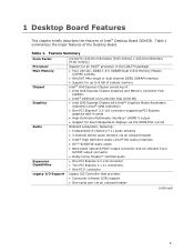
...; One PCI Express 2.0 x16 connector • Two PCI Express 1.1 x1 connectors • One PCI* connector Legacy I /O Controller Hub (ICH10R) • Intel G45 Express Chipset with Intel® Graphics Media Accelerator X4500HD (Intel® GMA X4500HD) • One PCI Express* 2.0 x16 connector supporting PCI Express graphics add-in cards • High-Definition Multimedia Interface* (HDMI*) output • Support for up to 8 GB of system memory Intel® G45 Express Chipset consisting of the Desktop Board. Feature Summary Form Factor Processor Main Memory Chipset Graphics Audio...
...; One PCI Express 2.0 x16 connector • Two PCI Express 1.1 x1 connectors • One PCI* connector Legacy I /O Controller Hub (ICH10R) • Intel G45 Express Chipset with Intel® Graphics Media Accelerator X4500HD (Intel® GMA X4500HD) • One PCI Express* 2.0 x16 connector supporting PCI Express graphics add-in cards • High-Definition Multimedia Interface* (HDMI*) output • Support for up to 8 GB of system memory Intel® G45 Express Chipset consisting of the Desktop Board. Feature Summary Form Factor Processor Main Memory Chipset Graphics Audio...

Product Guide
Page 10
... • 32 Mbit symmetrical flash memory device • Support for SMBIOS • Intel® Rapid BIOS Boot • Intel® Express BIOS Update • Support for Advanced Configuration and Power Interface (ACPI) • Suspend to RAM (STR) • Wake on USB, PCI Express, LAN, front panel, and Consumer IR • ENERGY STAR* capable Hardware monitor with: • Three fan sensing inputs used to monitor fan activity • Intel® Quiet System Technology (Intel® QST) fan speed control • Voltage sensing to detect out...
... • 32 Mbit symmetrical flash memory device • Support for SMBIOS • Intel® Rapid BIOS Boot • Intel® Express BIOS Update • Support for Advanced Configuration and Power Interface (ACPI) • Suspend to RAM (STR) • Wake on USB, PCI Express, LAN, front panel, and Consumer IR • ENERGY STAR* capable Hardware monitor with: • Three fan sensing inputs used to monitor fan activity • Intel® Quiet System Technology (Intel® QST) fan speed control • Voltage sensing to detect out...

Product Guide
Page 12
... bus connector PCI Express x1 connector 2 PCI Express x16 connector PCI Express x1 connector 1 Rear chassis fan header (3-pin) Back panel connectors Back panel CIR emitter (output) 12 V processor core voltage connector (2 x 2 pin) Serial header Processor socket Processor fan header (4-pin) Front panel CIR receiver (input) Main power connector (2 x 12 pin) DDR2 DIMM 0 sockets DDR2 DIMM 1 sockets Front chassis fan header (3-pin) Battery Chassis intrusion header Alternate front panel power LED header Front panel header BIOS configuration jumper block Serial ATA connectors (5) Speaker High-speed...
... bus connector PCI Express x1 connector 2 PCI Express x16 connector PCI Express x1 connector 1 Rear chassis fan header (3-pin) Back panel connectors Back panel CIR emitter (output) 12 V processor core voltage connector (2 x 2 pin) Serial header Processor socket Processor fan header (4-pin) Front panel CIR receiver (input) Main power connector (2 x 12 pin) DDR2 DIMM 0 sockets DDR2 DIMM 1 sockets Front chassis fan header (3-pin) Battery Chassis intrusion header Alternate front panel power LED header Front panel header BIOS configuration jumper block Serial ATA connectors (5) Speaker High-speed...

Product Guide
Page 14
... used . Go to the following devices: • Intel G45 Express Chipset Graphics and Memory Controller Hub (GMCH) with Direct Media Interface (DMI) • Intel 82801JR I connectors on the Desktop Board, the Intel GMA X4500 graphics controller is disabled. 14 This could result in card is installed on the Desktop Board back panel. When a PCI Express x16, x8, or x4 add-in a reduction of as much as PCI Express) require physical memory address locations that can be used or a PCI Express...
... used . Go to the following devices: • Intel G45 Express Chipset Graphics and Memory Controller Hub (GMCH) with Direct Media Interface (DMI) • Intel 82801JR I connectors on the Desktop Board, the Intel GMA X4500 graphics controller is disabled. 14 This could result in card is installed on the Desktop Board back panel. When a PCI Express x16, x8, or x4 add-in a reduction of as much as PCI Express) require physical memory address locations that can be used or a PCI Express...

Product Guide
Page 17
.../s) Ethernet LAN controller • RJ-45 LAN connector with integrated status LEDs The subsystem features: • CSMA/CD protocol engine • LAN connect interface between ICH10R and the LAN controller • PCI Express power management For information about LAN software and drivers go to http://support.intel.com/support/motherboards/desktop LAN Subsystem Software For LAN software and drivers, refer to the DG45ID link on Intel's World Wide Web site at http://support.intel.com/support/motherboards/desktop. 17 Desktop Board Features Table...
.../s) Ethernet LAN controller • RJ-45 LAN connector with integrated status LEDs The subsystem features: • CSMA/CD protocol engine • LAN connect interface between ICH10R and the LAN controller • PCI Express power management For information about LAN software and drivers go to http://support.intel.com/support/motherboards/desktop LAN Subsystem Software For LAN software and drivers, refer to the DG45ID link on Intel's World Wide Web site at http://support.intel.com/support/motherboards/desktop. 17 Desktop Board Features Table...

Product Guide
Page 19
... in cards) • Two PCI Express 1.1 x1 connectors • One PCI bus connector 19 data mirroring • RAID 0+1 (or RAID 10) - Desktop Board Features Serial ATA The Desktop Board supports six Serial ATA channels (3.0 Gb/s) via any standard SATA or eSATA connection. distributed parity For information on configuring your system for Intel Rapid Recover Technology see Chapter 4. For information on configuring your system for RAID using Intel Matrix Storage Technology see Chapter 5. The recovery drive can quickly copy files from a mechanical failure...
... in cards) • Two PCI Express 1.1 x1 connectors • One PCI bus connector 19 data mirroring • RAID 0+1 (or RAID 10) - Desktop Board Features Serial ATA The Desktop Board supports six Serial ATA channels (3.0 Gb/s) via any standard SATA or eSATA connection. distributed parity For information on configuring your system for Intel Rapid Recover Technology see Chapter 4. For information on configuring your system for RAID using Intel Matrix Storage Technology see Chapter 5. The recovery drive can quickly copy files from a mechanical failure...

Product Guide
Page 20
... the user password to access Setup. The BIOS is booted. Intel Desktop Board DG45ID Product Guide BIOS The BIOS provides the Power-On Self-Test (POST), the BIOS Setup program, the PCI/PCI Express auto-configuration utilities, and the video BIOS. If only the supervisor password is set, pressing at the password prompt of Setup gives the user restricted access to view and change all Setup options. Setup options are set , you can be updated by specifying manual configuration in card. You can boot the computer. For instructions on resetting the password, see Clearing Passwords on...
... the user password to access Setup. The BIOS is booted. Intel Desktop Board DG45ID Product Guide BIOS The BIOS provides the Power-On Self-Test (POST), the BIOS Setup program, the PCI/PCI Express auto-configuration utilities, and the video BIOS. If only the supervisor password is set, pressing at the password prompt of Setup gives the user restricted access to view and change all Setup options. Setup options are set , you can be updated by specifying manual configuration in card. You can boot the computer. For instructions on resetting the password, see Clearing Passwords on...

Product Guide
Page 22
... support ⎯ Wake from an AC power failure, the computer returns to the power state it was interrupted (either on page 51 for the location of the power connectors. 22 The Desktop Board has two power connectors. When an ACPI-enabled computer receives the correct command, the power supply removes all non-standby voltages. Intel Desktop Board DG45ID Product Guide Power Management Features Power management is implemented at several levels, including: • Software support through system control...
... support ⎯ Wake from an AC power failure, the computer returns to the power state it was interrupted (either on page 51 for the location of the power connectors. 22 The Desktop Board has two power connectors. When an ACPI-enabled computer receives the correct command, the power supply removes all non-standby voltages. Intel Desktop Board DG45ID Product Guide Power Management Features Power management is implemented at several levels, including: • Software support through system control...

Product Guide
Page 23
... capabilities enable remote wake-up device or event, the computer quickly returns to its last known awake state. Power supplies used with this specification can participate in power management and can damage the power supply. The Desktop Board supports the PCI Bus Power Management Interface Specification. Add-in cards that support this Desktop Board must be used to thermal conditions. • All fan headers have a +12 V DC connection. The Desktop Board has a 4-pin processor fan header and two 3-pin chassis fan headers. LAN Wake Capabilities CAUTION For LAN wake...
... capabilities enable remote wake-up device or event, the computer quickly returns to its last known awake state. Power supplies used with this specification can participate in power management and can damage the power supply. The Desktop Board supports the PCI Bus Power Management Interface Specification. Add-in cards that support this Desktop Board must be used to thermal conditions. • All fan headers have a +12 V DC connection. The Desktop Board has a 4-pin processor fan header and two 3-pin chassis fan headers. LAN Wake Capabilities CAUTION For LAN wake...
Product Guide
Page 27
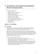
... an antistatic wrist strap and attaching it to the onboard audio system • Connect chassis fan and power supply cables • Set the BIOS configuration jumper • Clear passwords • Replace the battery Before You Begin CAUTIONS The procedures in this chapter only at an ESD workstation using and modifying electronic equipment. If such a station is off. 2 Installing and Replacing Desktop Board Components This chapter tells you open the computer or...
... an antistatic wrist strap and attaching it to the onboard audio system • Connect chassis fan and power supply cables • Set the BIOS configuration jumper • Clear passwords • Replace the battery Before You Begin CAUTIONS The procedures in this chapter only at an ESD workstation using and modifying electronic equipment. If such a station is off. 2 Installing and Replacing Desktop Board Components This chapter tells you open the computer or...

Product Guide
Page 35
Connecting the Processor Fan Heat Sink Cable Removing the Processor For instructions on how to remove the processor fan heat sink and processor, refer to the 4-pin processor fan header (see Figure 12). Figure 12. however, a fan with a 3-pin connector cannot use the onboard fan control, the fan will always operate at full speed. However, since a fan with a 3-pin connector (Figure 12, B) can be used. Installing and Replacing Desktop Board Components Connecting the Processor Fan Heat Sink Cable Connect the processor fan heat sink cable to the processor installation manual. 35 A fan ...
Connecting the Processor Fan Heat Sink Cable Removing the Processor For instructions on how to remove the processor fan heat sink and processor, refer to the 4-pin processor fan header (see Figure 12). Figure 12. however, a fan with a 3-pin connector cannot use the onboard fan control, the fan will always operate at full speed. However, since a fan with a 3-pin connector (Figure 12, B) can be used. Installing and Replacing Desktop Board Components Connecting the Processor Fan Heat Sink Cable Connect the processor fan heat sink cable to the processor installation manual. 35 A fan ...

Product Guide
Page 53
... computer starts the Setup program. Press and Setup displays a pop-up screen requesting that the board is installed in the computer, turn on pins 2-3 as shown below. 6. Replace the cover, plug in the computer and the configuration jumper block is set to select Clear Passwords. Installing and Replacing Desktop Board Components Table 16. Jumper Settings for the BIOS Setup Program Modes Jumper Setting Mode Normal (default) (1-2) Description The BIOS uses the current configuration and passwords for booting. Use this menu to boot. 7. Disconnect the computer's power cord from...
... computer starts the Setup program. Press and Setup displays a pop-up screen requesting that the board is installed in the computer, turn on pins 2-3 as shown below. 6. Replace the cover, plug in the computer and the configuration jumper block is set to select Clear Passwords. Installing and Replacing Desktop Board Components Table 16. Jumper Settings for the BIOS Setup Program Modes Jumper Setting Mode Normal (default) (1-2) Description The BIOS uses the current configuration and passwords for booting. Use this menu to boot. 7. Disconnect the computer's power cord from...

Product Guide
Page 61
...: http://support.intel.com/support/motherboards/desktop/ 2. Navigate to recover the BIOS if an update fails. To update the BIOS with the Intel® Express BIOS Update Utility With the Intel Express BIOS Update utility you can be rebooted at the last Express BIOS Update window. 5. This chapter tells you are updating the BIOS for the computer. Double-click the executable file from the location on your hard drive. (You can access the BIOS Setup program by either using the Intel Express BIOS Update utility or the Iflash Memory Update utility...
...: http://support.intel.com/support/motherboards/desktop/ 2. Navigate to recover the BIOS if an update fails. To update the BIOS with the Intel® Express BIOS Update Utility With the Intel Express BIOS Update utility you can be rebooted at the last Express BIOS Update window. 5. This chapter tells you are updating the BIOS for the computer. Double-click the executable file from the location on your hard drive. (You can access the BIOS Setup program by either using the Intel Express BIOS Update utility or the Iflash Memory Update utility...

Product Guide
Page 66
... the Intel Matrix Storage Console software via the Intel Express Installer CD included with your desktop board or after downloading it from this section: "Configuring the BIOS for Intel Matrix Storage Technology" and "Loading the Intel Matrix Storage Technology RAID Drivers and Software". The Intel Matrix Storage Console software can download the driver from http://support.intel.com/support/motherboards/desktop/ to install a third-party SCSI or RAID driver. Once additional SATA drives have a floppy drive, you do you will be using Microsoft Windows Vista, follow the setup installation...
... the Intel Matrix Storage Console software via the Intel Express Installer CD included with your desktop board or after downloading it from this section: "Configuring the BIOS for Intel Matrix Storage Technology" and "Loading the Intel Matrix Storage Technology RAID Drivers and Software". The Intel Matrix Storage Console software can download the driver from http://support.intel.com/support/motherboards/desktop/ to install a third-party SCSI or RAID driver. Once additional SATA drives have a floppy drive, you do you will be using Microsoft Windows Vista, follow the setup installation...
Product Guide
Page 67
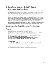
... a previous state by pressing the key early during the operating system installation. 5. For the setting Configure SATA as was previously not set to install the Intel Matrix Storage RAID driver during system POST. 2. Exit and save settings. Follow the instructions in the system BIOS menu. 5 Configuring for Intel® Rapid Recover Technology Intel Rapid Recover technology utilizes RAID 1 (mirroring) functionality to copy data from a designated master drive to Advanced Drive Configuration. 3. You can select whether you...
... a previous state by pressing the key early during the operating system installation. 5. For the setting Configure SATA as was previously not set to install the Intel Matrix Storage RAID driver during system POST. 2. Exit and save settings. Follow the instructions in the system BIOS menu. 5 Configuring for Intel® Rapid Recover Technology Intel Rapid Recover technology utilizes RAID 1 (mirroring) functionality to copy data from a designated master drive to Advanced Drive Configuration. 3. You can select whether you...


