Product Guide
Page 5
Contents 1 Desktop Board Features Supported Operating Systems 11 Desktop Board Components 12 Processor ...14 Intel® H55 Express Chipset 14 Main Memory...15 Graphics Subsystem 15 Integrated Graphics 15 Analog Display (VGA 15 Digital Visual Interface (DVI-D 16 PCI Express* x16 Graphics 16 Audio Subsystem 16 LAN ...
Contents 1 Desktop Board Features Supported Operating Systems 11 Desktop Board Components 12 Processor ...14 Intel® H55 Express Chipset 14 Main Memory...15 Graphics Subsystem 15 Integrated Graphics 15 Analog Display (VGA 15 Digital Visual Interface (DVI-D 16 PCI Express* x16 Graphics 16 Audio Subsystem 16 LAN ...

Product Guide
Page 6
... Clearing Passwords 51 Replacing the Battery 52 3 Updating the BIOS Updating the BIOS with the Intel® Express BIOS Update Utility 59 Updating the BIOS with the ISO Image BIOS Update File or the Iflash Memory Update Utility 60 Obtaining the BIOS Update File 60 Updating the BIOS with the ISO Image...
... Clearing Passwords 51 Replacing the Battery 52 3 Updating the BIOS Updating the BIOS with the Intel® Express BIOS Update Utility 59 Updating the BIOS with the ISO Image BIOS Update File or the Iflash Memory Update Utility 60 Obtaining the BIOS Update File 60 Updating the BIOS with the ISO Image...

Product Guide
Page 7
...the Protective Cover 32 10. Use DDR3 DIMMs 36 16. Removing a PCI Express x16 Graphics Card 40 19. Internal Headers 42 21. Intel Desktop Board DH55PJ China RoHS Material Self Declaration Table 70 vii LAN Connector LEDs 17 3. Lift the Load Plate 30 8. Secure the ... 48 23. Back Panel Audio Connectors 47 22. Install the Processor 32 11. Installing a PCI Express x16 Graphics Card 39 18. Dual Channel Memory Configuration Example 35 15. Installing the I/O Shield 27 5. Connecting a Serial ATA Cable 41 20. Unlatch the Socket Lever 29 7. and Component...
...the Protective Cover 32 10. Use DDR3 DIMMs 36 16. Removing a PCI Express x16 Graphics Card 40 19. Internal Headers 42 21. Intel Desktop Board DH55PJ China RoHS Material Self Declaration Table 70 vii LAN Connector LEDs 17 3. Lift the Load Plate 30 8. Secure the ... 48 23. Back Panel Audio Connectors 47 22. Install the Processor 32 11. Installing a PCI Express x16 Graphics Card 39 18. Dual Channel Memory Configuration Example 35 15. Installing the I/O Shield 27 5. Connecting a Serial ATA Cable 41 20. Unlatch the Socket Lever 29 7. and Component...

Product Guide
Page 9
... MHz and DDR3 1066 MHz DIMMs • Support for 1 Gb and 2 Gb memory technology • Support for up to 8 GB of system memory with two DIMMs using 2 Gb memory technology • Support for non-ECC memory • Integrated graphics support for processors with Intel Graphics Technology: ― VGA ― DVI-D • Discrete graphics support for...
... MHz and DDR3 1066 MHz DIMMs • Support for 1 Gb and 2 Gb memory technology • Support for up to 8 GB of system memory with two DIMMs using 2 Gb memory technology • Support for non-ECC memory • Integrated graphics support for processors with Intel Graphics Technology: ― VGA ― DVI-D • Discrete graphics support for...

Product Guide
Page 15
The BIOS will attempt to a maximum of 4 GB of memory. Graphics Subsystem The board supports either integrated graphics (Intel Graphics Technology) or PCI Express 2.0 x16 graphics. The VGA port is enabled for the POST whenever a monitor is ...port supports analog displays. Desktop Board Features Main Memory NOTE To be fully compliant with all applicable Intel ® SDRAM memory specifications, the board should be populated with Intel Graphics Technology. Integrated Graphics The board supports integrated graphics through the Intel Flexible Display Interface (FDI) for normal operation...
The BIOS will attempt to a maximum of 4 GB of memory. Graphics Subsystem The board supports either integrated graphics (Intel Graphics Technology) or PCI Express 2.0 x16 graphics. The VGA port is enabled for the POST whenever a monitor is ...port supports analog displays. Desktop Board Features Main Memory NOTE To be fully compliant with all applicable Intel ® SDRAM memory specifications, the board should be populated with Intel Graphics Technology. Integrated Graphics The board supports integrated graphics through the Intel Flexible Display Interface (FDI) for normal operation...

Product Guide
Page 20
... enable the board to be observed via the BIOS Setup program, Intel® Desktop Utilities, or third-party software. 20 The board... and Fan Speed Control The features of the hardware monitoring and fan speed control include: • Intel Quiet System Technology, delivering acoustically-optimized thermal management • Thermal sensors in the processor and PCH,.... A supervisor password and a user password can be accessed and who can boot the computer. Intel Desktop Board DH55PJ Product Guide Security Passwords The BIOS includes security features that can adjust fan speed...
... enable the board to be observed via the BIOS Setup program, Intel® Desktop Utilities, or third-party software. 20 The board... and Fan Speed Control The features of the hardware monitoring and fan speed control include: • Intel Quiet System Technology, delivering acoustically-optimized thermal management • Thermal sensors in the processor and PCH,.... A supervisor password and a user password can be accessed and who can boot the computer. Intel Desktop Board DH55PJ Product Guide Security Passwords The BIOS includes security features that can adjust fan speed...
Product Guide
Page 23
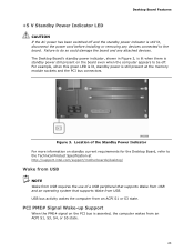
... that supports Wake from USB. Figure 3. Failure to do so could damage the board and any devices connected to the Technical Product Specification at the memory module sockets and the PCI bus connectors. For example, when this green LED is lit, standby power is asserted, the computer wakes from an ACPI..., S4, or S5 state. 23 PCI PME# Signal Wake-up Support When the PME# signal on the PCI bus is still present at http://support.intel.com/support/motherboards/desktop/ Wake from USB NOTE Wake from USB requires the use of the Standby Power Indicator For more information on the board...
... that supports Wake from USB. Figure 3. Failure to do so could damage the board and any devices connected to the Technical Product Specification at the memory module sockets and the PCI bus connectors. For example, when this green LED is lit, standby power is asserted, the computer wakes from an ACPI..., S4, or S5 state. 23 PCI PME# Signal Wake-up Support When the PME# signal on the PCI bus is still present at http://support.intel.com/support/motherboards/desktop/ Wake from USB NOTE Wake from USB requires the use of the Standby Power Indicator For more information on the board...
Product Guide
Page 24
... the S5 state, the only PS/2 activity that is not plugged into a wall socket, the battery has an estimated life of the board's beep codes. Intel Desktop Board DH55PJ Product Guide PCI Express WAKE# Signal Wake-up Support When the WAKE# signal on the Desktop Board. The BIOS can wake the... state. Refer to page 52 for a description of three years. Real-Time Clock Subsystem A coin-cell battery (CR2032) powers the real-time clock and CMOS memory. Replace the battery with standby power applied by the power supply. Go to Appendix A for instructions on some keyboards.
... the S5 state, the only PS/2 activity that is not plugged into a wall socket, the battery has an estimated life of the board's beep codes. Intel Desktop Board DH55PJ Product Guide PCI Express WAKE# Signal Wake-up Support When the WAKE# signal on the Desktop Board. The BIOS can wake the... state. Refer to page 52 for a description of three years. Real-Time Clock Subsystem A coin-cell battery (CR2032) powers the real-time clock and CMOS memory. Replace the battery with standby power applied by the power supply. Go to Appendix A for instructions on some keyboards.
Product Guide
Page 25
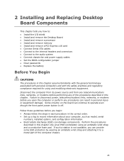
... guidelines before you how to: • Install the I/O shield • Install and remove the Desktop Board • Install and remove a processor • Install and remove memory • Install and remove a PCI Express x16 card • Connect Serial ATA cables • Connect to the internal headers and connectors • Connect to the...
... guidelines before you how to: • Install the I/O shield • Install and remove the Desktop Board • Install and remove a processor • Install and remove memory • Install and remove a PCI Express x16 card • Connect Serial ATA cables • Connect to the internal headers and connectors • Connect to the...

Product Guide
Page 35
... will result in speed and size (see Figure 14). Installing and Replacing Desktop Board Components Installing and Removing System Memory NOTE To be fully compliant with all applicable Intel SDRAM memory specifications, the board requires DIMMs that support the Serial Presence Detect (SPD) data structure. The Desktop Board has two 240-pin DDR3...
... will result in speed and size (see Figure 14). Installing and Replacing Desktop Board Components Installing and Removing System Memory NOTE To be fully compliant with all applicable Intel SDRAM memory specifications, the board requires DIMMs that support the Serial Presence Detect (SPD) data structure. The Desktop Board has two 240-pin DDR3...

Product Guide
Page 52
...power supply extends the life of the battery. Replacing the Battery A coin-cell battery (CR2032) powers the real-time clock and CMOS memory. When the computer is accurate to ± 13 minutes/year at 25 ºC with local environmental regulations. Disposal of used batteries.... Batterier bør om muligt genbruges. Bortskaffelse af brugte batterier bør foregå i overensstemmelse med gældende miljølovgivning. 52 Intel Desktop Board DH55PJ Product Guide 8. Turn off the computer. Replace the cover, plug in , the standby current from the AC power source. ...
...power supply extends the life of the battery. Replacing the Battery A coin-cell battery (CR2032) powers the real-time clock and CMOS memory. When the computer is accurate to ± 13 minutes/year at 25 ºC with local environmental regulations. Disposal of used batteries.... Batterier bør om muligt genbruges. Bortskaffelse af brugte batterier bør foregå i overensstemmelse med gældende miljølovgivning. 52 Intel Desktop Board DH55PJ Product Guide 8. Turn off the computer. Replace the cover, plug in , the standby current from the AC power source. ...

Product Guide
Page 59
... utility you are updating the BIOS for the computer. You can access the BIOS Setup program by either using the Intel Express BIOS Update utility or the Iflash Memory Update utility, and how to a removable USB device. Go to complete the BIOS update. 59 Double-click the ... the instructions provided in an automated update utility that combines the functionality of the Intel® Flash Memory Update Utility and the ease of use of Windows-based installation wizards. Updating the BIOS with the Intel Express BIOS Update utility: 1. Navigate to view and change the BIOS settings for...
... utility you are updating the BIOS for the computer. You can access the BIOS Setup program by either using the Intel Express BIOS Update utility or the Iflash Memory Update utility, and how to a removable USB device. Go to complete the BIOS update. 59 Double-click the ... the instructions provided in an automated update utility that combines the functionality of the Intel® Flash Memory Update Utility and the ease of use of Windows-based installation wizards. Updating the BIOS with the Intel Express BIOS Update utility: 1. Navigate to view and change the BIOS settings for...
Product Guide
Page 60
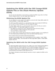
...file. The Iflash BIOS update file contains: • New BIOS file (including the Intel® Management Engine Firmware Image) • Intel® Integrator Toolkit Configuration File (optional) • Intel Flash Memory Update Utility You can update to a new version of the BIOS by using either of... these files through your computer supplier or by navigating to the Intel Desktop Board DH55PJ page on...
...file. The Iflash BIOS update file contains: • New BIOS file (including the Intel® Management Engine Firmware Image) • Intel® Integrator Toolkit Configuration File (optional) • Intel Flash Memory Update Utility You can update to a new version of the BIOS by using either of... these files through your computer supplier or by navigating to the Intel Desktop Board DH55PJ page on...
Product Guide
Page 61
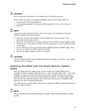
... minutes. Wait for creating a bootable CD-ROM that was created in flash memory NOTE Review the instructions distributed with the Iflash Memory Update Utility With the Iflash Memory update utility you to update the BIOS and Intel Management Engine in the CD-ROM drive of writing an ISO image file to... CD, burn the data to complete. The utility available on the Intel World Wide Web site ...
... minutes. Wait for creating a bootable CD-ROM that was created in flash memory NOTE Review the instructions distributed with the Iflash Memory Update Utility With the Iflash Memory update utility you to update the BIOS and Intel Management Engine in the CD-ROM drive of writing an ISO image file to... CD, burn the data to complete. The utility available on the Intel World Wide Web site ...
Product Guide
Page 63
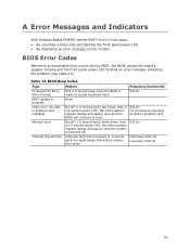
... 1500 Hz 63 BIOS Beep Codes Type F2 Setup/F10 Boot Menu Prompt BIOS update in progress Video error (no addin graphics card installed) Memory error Thermal trip warning Pattern One 0.5 second beep when the BIOS is powered off. 932 Hz Alternate high and low beeps (1.0 second each... None Frequency/Comments 932 Hz On-off (1.0 second each ) for eight beeps followed by system shut down. Table 14. A Error Messages and Indicators Intel Desktop Board DH55PJ reports POST errors in graphics card On-off (1.0 second each) three times, then a 2.5-second pause (off), the entire pattern repeats...
... 1500 Hz 63 BIOS Beep Codes Type F2 Setup/F10 Boot Menu Prompt BIOS update in progress Video error (no addin graphics card installed) Memory error Thermal trip warning Pattern One 0.5 second beep when the BIOS is powered off. 932 Hz Alternate high and low beeps (1.0 second each... None Frequency/Comments 932 Hz On-off (1.0 second each ) for eight beeps followed by system shut down. Table 14. A Error Messages and Indicators Intel Desktop Board DH55PJ reports POST errors in graphics card On-off (1.0 second each) three times, then a 2.5-second pause (off), the entire pattern repeats...
Product Guide
Page 64
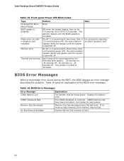
..., .25 seconds off, .25 seconds on for 0.5 seconds, then off . Table 16. System did not find a device to reset values. Intel Desktop Board DH55PJ Product Guide Table 15. Table 16 gives an explanation of 16 blinks. Run Setup to boot. 64 The CMOS checksum is powered... off . For processors requiring an add-in progress Video error (no memory was removed, then memory may be bad. BIOS Error Messages When a recoverable error occurs during the POST, the BIOS displays an error message describing the...
..., .25 seconds off, .25 seconds on for 0.5 seconds, then off . Table 16. System did not find a device to reset values. Intel Desktop Board DH55PJ Product Guide Table 15. Table 16 gives an explanation of 16 blinks. Run Setup to boot. 64 The CMOS checksum is powered... off . For processors requiring an add-in progress Video error (no memory was removed, then memory may be bad. BIOS Error Messages When a recoverable error occurs during the POST, the BIOS displays an error message describing the...


