Product Guide
Page 5
...Components 12 Processor ...14 Main Memory...14 Intel® Q35 Express Chipset 15 Intel Q35 Graphics Subsystem 16 Intel® GMA 3100 Graphics Controller 16 Audio Subsystem 17 Legacy Input/Output (I/O) Controller 18 LAN Subsystem 18 RJ-45 LAN Connector LEDs 19 Intel® Active Management Technology (Intel® AMT 19 Intel AMT ...Status Indicator 20 Hi-Speed USB 2.0 Support 21 Enhanced IDE Interface 21 Serial ATA...21 Serial ATA RAID 21 Intel® Rapid Recover Technology 22 Expandability...22 BIOS ...22 Serial ATA and IDE Auto Configuration 22 PCI* and PCI Express* Auto ...
...Components 12 Processor ...14 Main Memory...14 Intel® Q35 Express Chipset 15 Intel Q35 Graphics Subsystem 16 Intel® GMA 3100 Graphics Controller 16 Audio Subsystem 17 Legacy Input/Output (I/O) Controller 18 LAN Subsystem 18 RJ-45 LAN Connector LEDs 19 Intel® Active Management Technology (Intel® AMT 19 Intel AMT ...Status Indicator 20 Hi-Speed USB 2.0 Support 21 Enhanced IDE Interface 21 Serial ATA...21 Serial ATA RAID 21 Intel® Rapid Recover Technology 22 Expandability...22 BIOS ...22 Serial ATA and IDE Auto Configuration 22 PCI* and PCI Express* Auto ...
Product Guide
Page 6
Intel Desktop Board DQ35MP Product Guide 2 Installing and Replacing Desktop Board Components Before You Begin 31 Installation Precautions 32 Prevent Power Supply Overload 32 Observe Safety and Regulatory Requirements 32 Installing the I/O Shield 33 Installing and Removing the Desktop Board 34 Installing and Removing a Processor 35 Installing a Processor 35 Installing the Processor... Fan Heat Sink 38 Connecting the Processor Fan Heat Sink Cable 39 Removing the Processor 40 Installing and Removing...
Intel Desktop Board DQ35MP Product Guide 2 Installing and Replacing Desktop Board Components Before You Begin 31 Installation Precautions 32 Prevent Power Supply Overload 32 Observe Safety and Regulatory Requirements 32 Installing the I/O Shield 33 Installing and Removing the Desktop Board 34 Installing and Removing a Processor 35 Installing a Processor 35 Installing the Processor... Fan Heat Sink 38 Connecting the Processor Fan Heat Sink Cable 39 Removing the Processor 40 Installing and Removing...

Product Guide
Page 7
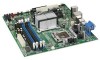
... 37 11. Dual Channel Memory Configuration with Three DIMMs 42 17. Intel AMT Status Indicator 20 4. Desktop Board DQ35MP Mounting Screw Hole Locations 34 7. Connecting the Processor Fan Heat Sink Cable to the Processor Fan Header ..........39 14. Dual Channel Memory Configuration with Four DIMMs ...Plate 38 13. Remove the Protective Socket Cover 36 10. Desktop Board DQ35MP Components 12 2. Installing a DIMM 44 vii Install the Processor 37 12. Lift the Socket Lever 35 8. Dual Channel Memory Configuration with Two DIMMs 41 15. Installing the I/O Shield 33 6. Contents...
... 37 11. Dual Channel Memory Configuration with Three DIMMs 42 17. Intel AMT Status Indicator 20 4. Desktop Board DQ35MP Mounting Screw Hole Locations 34 7. Connecting the Processor Fan Heat Sink Cable to the Processor Fan Header ..........39 14. Dual Channel Memory Configuration with Four DIMMs ...Plate 38 13. Remove the Protective Socket Cover 36 10. Desktop Board DQ35MP Components 12 2. Installing a DIMM 44 vii Install the Processor 37 12. Lift the Socket Lever 35 8. Dual Channel Memory Configuration with Two DIMMs 41 15. Installing the I/O Shield 33 6. Contents...

Product Guide
Page 9
...; One IDE interface with ATA-66/100 support for two devices continued 9 Feature Summary Form Factor Processor Main Memory Chipset Graphics microATX (243.84 millimeters [9.60 inches] x 243.84 millimeters [9.60 inches]) Support for an Intel® processor in the LGA775 package • Four 240-pin, DDR2 1.8 V (only) SDRAM Dual Inline Memory Module...
...; One IDE interface with ATA-66/100 support for two devices continued 9 Feature Summary Form Factor Processor Main Memory Chipset Graphics microATX (243.84 millimeters [9.60 inches] x 243.84 millimeters [9.60 inches]) Support for an Intel® processor in the LGA775 package • Four 240-pin, DDR2 1.8 V (only) SDRAM Dual Inline Memory Module...

Product Guide
Page 14
... a notification to this effect on installing or upgrading the processor, page 35 in Chapter 2 • Supported processors for Desktop Board DQ35MP, http://www.intel.com/go/findCPU Main Memory NOTE To be fully compliant with all applicable Intel ® SDRAM memory specifications, the board should be populated... with the Desktop Board and must be purchased separately. Intel Desktop Board DQ35MP Product Guide Processor CAUTION Failure to use an appropriate power supply and/or not connecting the 12 V (2 x 2 pin) power connector to ...
... a notification to this effect on installing or upgrading the processor, page 35 in Chapter 2 • Supported processors for Desktop Board DQ35MP, http://www.intel.com/go/findCPU Main Memory NOTE To be fully compliant with all applicable Intel ® SDRAM memory specifications, the board should be populated... with the Desktop Board and must be purchased separately. Intel Desktop Board DQ35MP Product Guide Processor CAUTION Failure to use an appropriate power supply and/or not connecting the 12 V (2 x 2 pin) power connector to ...

Product Guide
Page 15
The component also provides integrated graphics capabilities supporting 3D, 2D, and display capabilities. ICH9DO is a centralized controller for more information about the Intel Q35 Express Chipset: http://developer.intel.com/products/chipsets/index.htm 15 Related Links: Go to the following link for the board's I /O Controller Hub (ICH9DO) with gold-plated contacts, 1.8 V only...256 Mb technology • Up to 4.0 GB utilizing 512 Mb or 1 Gb technology • Up to 8.0 GB utilizing 1 Gb technology Related Links: Go to the processor, memory, PCI Express bus, and the DMI interconnect.
The component also provides integrated graphics capabilities supporting 3D, 2D, and display capabilities. ICH9DO is a centralized controller for more information about the Intel Q35 Express Chipset: http://developer.intel.com/products/chipsets/index.htm 15 Related Links: Go to the following link for the board's I /O Controller Hub (ICH9DO) with gold-plated contacts, 1.8 V only...256 Mb technology • Up to 4.0 GB utilizing 512 Mb or 1 Gb technology • Up to 8.0 GB utilizing 1 Gb technology Related Links: Go to the processor, memory, PCI Express bus, and the DMI interconnect.

Product Guide
Page 21
...• Up to three internal headers) via ICH9DO, connecting one device per channel. distributed parity For information on configuring your system for RAID using Intel® Matrix Storage Technology see Chapter 4. 21 This may be required to USB 1.1 operation. USB 2.0 support requires both an operating system and...fully support USB 2.0 transfer rates. Serial ATA RAID The ICH9DO supports the following RAID (Redundant Array of information between the processor and peripheral devices such as an eSATA channel. data striping • RAID 1 - data striping and mirroring • RAID 5 -
...• Up to three internal headers) via ICH9DO, connecting one device per channel. distributed parity For information on configuring your system for RAID using Intel® Matrix Storage Technology see Chapter 4. 21 This may be required to USB 1.1 operation. USB 2.0 support requires both an operating system and...fully support USB 2.0 transfer rates. Serial ATA RAID The ICH9DO supports the following RAID (Redundant Array of information between the processor and peripheral devices such as an eSATA channel. data striping • RAID 1 - data striping and mirroring • RAID 5 -
Product Guide
Page 25
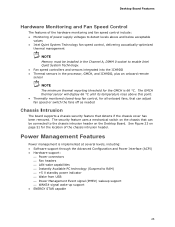
...feature that can be installed in the Channel A, DIMM 0 socket to enable Intel Quiet System Technology. • Fan speed controllers and sensors integrated into the ICH9DO • Thermal sensors in the processor, GMCH, and ICH9DO, plus an onboard remote sensor NOTE The minimum thermal ... intrusion header. The GMCH thermal sensor will display 66 °C until its temperature rises above and below acceptable values • Intel Quiet System Technology fan speed control, delivering acoustically-optimized thermal management NOTE Memory must be connected to the chassis intrusion header on...
...feature that can be installed in the Channel A, DIMM 0 socket to enable Intel Quiet System Technology. • Fan speed controllers and sensors integrated into the ICH9DO • Thermal sensors in the processor, GMCH, and ICH9DO, plus an onboard remote sensor NOTE The minimum thermal ... intrusion header. The GMCH thermal sensor will display 66 °C until its temperature rises above and below acceptable values • Intel Quiet System Technology fan speed control, delivering acoustically-optimized thermal management NOTE Memory must be connected to the chassis intrusion header on...

Product Guide
Page 26
When an ACPI-enabled computer receives the correct command, the power supply removes all non-standby voltages. The Desktop Board has a 4-pin processor fan header and two 3-pin chassis fan headers. 26 Hardware Support Power Connectors ATX12V-compliant power supplies can be set by using the ... is as needed. • All fan headers have a +12 V DC connection. See Figure 26 on or off the computer power through system control. Intel Desktop Board DQ35MP Product Guide ACPI ACPI gives the operating system direct control over the power management and Plug and Play functions of the power...
When an ACPI-enabled computer receives the correct command, the power supply removes all non-standby voltages. The Desktop Board has a 4-pin processor fan header and two 3-pin chassis fan headers. 26 Hardware Support Power Connectors ATX12V-compliant power supplies can be set by using the ... is as needed. • All fan headers have a +12 V DC connection. See Figure 26 on or off the computer power through system control. Intel Desktop Board DQ35MP Product Guide ACPI ACPI gives the operating system direct control over the power management and Plug and Play functions of the power...

Product Guide
Page 31
... Replacing Desktop Board Components This chapter tells you how to: • Install the I/O shield • Install and remove the Desktop Board • Install and remove a processor • Install and remove memory • Install and remove a PCI Express x16 card • Connect the IDE and Serial ATA cables • Connect to the...
... Replacing Desktop Board Components This chapter tells you how to: • Install the I/O shield • Install and remove the Desktop Board • Install and remove a processor • Install and remove memory • Install and remove a PCI Express x16 card • Connect the IDE and Serial ATA cables • Connect to the...

Product Guide
Page 32
... requirements. Related Links For information about regulatory compliance, go to qualified technical personnel. Intel Desktop Board DQ35MP Product Guide Installation Precautions When you install and test the Intel Desktop Board, observe all warnings and cautions in this section and the instructions supplied ...8226; Sharp pins on printed circuit assemblies • Rough edges and sharp corners on the chassis • Hot components (such as processors, voltage regulators, and heat sinks) • Damage to wires that instruct you increase safety risk and the possibility of the power ...
... requirements. Related Links For information about regulatory compliance, go to qualified technical personnel. Intel Desktop Board DQ35MP Product Guide Installation Precautions When you install and test the Intel Desktop Board, observe all warnings and cautions in this section and the instructions supplied ...8226; Sharp pins on printed circuit assemblies • Rough edges and sharp corners on the chassis • Hot components (such as processors, voltage regulators, and heat sinks) • Damage to wires that instruct you increase safety risk and the possibility of the power ...

Product Guide
Page 35
Figure 7. Observe the precautions in "Before You Begin" on page 28). Installing a Processor CAUTION Before installing or removing the processor, make sure the AC power has been removed by pushing the lever down and away from the computer; Open the socket lever by unplugging the ... indicator should not be lit (see Figure 4 on page 31. 2. Failure to the Desktop Board are given below. Lift the Socket Lever 35 To install a processor, follow these instructions: 1. Installing and Replacing Desktop Board Components Installing and Removing...
Figure 7. Observe the precautions in "Before You Begin" on page 28). Installing a Processor CAUTION Before installing or removing the processor, make sure the AC power has been removed by pushing the lever down and away from the computer; Open the socket lever by unplugging the ... indicator should not be lit (see Figure 4 on page 31. 2. Failure to the Desktop Board are given below. Lift the Socket Lever 35 To install a processor, follow these instructions: 1. Installing and Replacing Desktop Board Components Installing and Removing...
Product Guide
Page 36
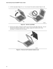
Figure 8. Lift the load plate (Figure 8, A). Lift the Load Plate 4. Do not discard the protective socket cover. Always replace the socket cover if the processor is removed from the load plate (Figure 9). Do not touch the socket contacts (Figure 8, B). Remove the Protective Socket Cover 36 Remove the plastic protective socket cover from the socket. Figure 9. Intel Desktop Board DQ35MP Product Guide 3.
Figure 8. Lift the load plate (Figure 8, A). Lift the Load Plate 4. Do not discard the protective socket cover. Always replace the socket cover if the processor is removed from the load plate (Figure 9). Do not touch the socket contacts (Figure 8, B). Remove the Protective Socket Cover 36 Remove the plastic protective socket cover from the socket. Figure 9. Intel Desktop Board DQ35MP Product Guide 3.

Product Guide
Page 37
... in Figure 11. Figure 11. Always replace the processor cover if the processor is removed from the Protective Processor Cover 6. Hold the processor with the socket (Figure 11, C). Install the Processor 37 Installing and Replacing Desktop Board Components 5. Remove the processor from the protective processor cover. Hold the processor only at the edges, being careful not to the...
... in Figure 11. Figure 11. Always replace the processor cover if the processor is removed from the Protective Processor Cover 6. Hold the processor with the socket (Figure 11, C). Install the Processor 37 Installing and Replacing Desktop Board Components 5. Remove the processor from the protective processor cover. Hold the processor only at the edges, being careful not to the...

Product Guide
Page 38
Figure 12. Intel Desktop Board DQ35MP Product Guide 7. Close the Load Plate Installing the Processor Fan Heat Sink Desktop Board DQ35MP has mounting holes for a processor fan heat sink. Pressing down on how to attach the processor fan heat sink to the Desktop Board, refer to the boxed processor manual. 38 For instructions on the load plate (Figure 12, A), close and engage the socket lever (Figure 12, B).
Figure 12. Intel Desktop Board DQ35MP Product Guide 7. Close the Load Plate Installing the Processor Fan Heat Sink Desktop Board DQ35MP has mounting holes for a processor fan heat sink. Pressing down on how to attach the processor fan heat sink to the Desktop Board, refer to the boxed processor manual. 38 For instructions on the load plate (Figure 12, A), close and engage the socket lever (Figure 12, B).

Product Guide
Page 39
However, since the fan with a 3-pin connector (Figure 13, B) can be used. Figure 13. Connecting the Processor Fan Heat Sink Cable to the 4-pin processor fan header (see Figure 13). however, a fan with a 3-pin connector cannot use the onboard fan control, the fan will always operate at full speed. Installing and Replacing Desktop Board Components Connecting the Processor Fan Heat Sink Cable Connect the processor fan heat sink cable to the Processor Fan Header 39 A fan with a 4-pin connector as shown in Figure 13, A is recommended;
However, since the fan with a 3-pin connector (Figure 13, B) can be used. Figure 13. Connecting the Processor Fan Heat Sink Cable to the 4-pin processor fan header (see Figure 13). however, a fan with a 3-pin connector cannot use the onboard fan control, the fan will always operate at full speed. Installing and Replacing Desktop Board Components Connecting the Processor Fan Heat Sink Cable Connect the processor fan heat sink cable to the Processor Fan Header 39 A fan with a 4-pin connector as shown in Figure 13, A is recommended;
Product Guide
Page 40
... requires DIMMs that support the Serial Presence Detect (SPD) data structure. NOTE Regardless of the Intel Management Engine feature. 40 Installing and Removing Memory NOTE To be populated. Intel Desktop Board DQ35MP Product Guide Removing the Processor For instructions on how to remove the processor fan heat sink and processor, refer to the processor installation manual.
... requires DIMMs that support the Serial Presence Detect (SPD) data structure. NOTE Regardless of the Intel Management Engine feature. 40 Installing and Removing Memory NOTE To be populated. Intel Desktop Board DQ35MP Product Guide Removing the Processor For instructions on how to remove the processor fan heat sink and processor, refer to the processor installation manual.

Product Guide
Page 57
Figure 26 shows the location of the Desktop Board power connectors. Figure 26. Connect the 12 V processor core voltage power supply cable to the 2 x 12 pin connector. 3. Observe the precautions in damage to the board or the system may result in "Before ...
Figure 26 shows the location of the Desktop Board power connectors. Figure 26. Connect the 12 V processor core voltage power supply cable to the 2 x 12 pin connector. 3. Observe the precautions in damage to the board or the system may result in "Before ...

Product Guide
Page 77
... Channel B. BIOS Error Messages Error Message PROCESSOR_THERMAL_TRIP_ERROR MULTI_BIT_ECC_ERROR SINGLE_BIT_ECC_ERROR CMOS_BATTERY_ERROR CMOS_CHECKSUM_ERROR CMOS_TIMER_ERROR MEMORY_SIZE_DECREASE_ERROR INTRUDER_DETECTION_ERROR SPD_TOLER_ERROR MEM_OPTIMAL_ERROR Explanation Processor was opened. Maximum memory performance is required for reliable operation. Beep Codes Beep 3 Siren Description No memory Processor overheat (on the monitor BIOS Beep Codes The BIOS also issues a beep code (one long tone...
... Channel B. BIOS Error Messages Error Message PROCESSOR_THERMAL_TRIP_ERROR MULTI_BIT_ECC_ERROR SINGLE_BIT_ECC_ERROR CMOS_BATTERY_ERROR CMOS_CHECKSUM_ERROR CMOS_TIMER_ERROR MEMORY_SIZE_DECREASE_ERROR INTRUDER_DETECTION_ERROR SPD_TOLER_ERROR MEM_OPTIMAL_ERROR Explanation Processor was opened. Maximum memory performance is required for reliable operation. Beep Codes Beep 3 Siren Description No memory Processor overheat (on the monitor BIOS Beep Codes The BIOS also issues a beep code (one long tone...


