

Product Specification
Page 2
... before being incorporated into a revision of the Intel® Desktop Board D425KT and Intel® Desktop Board D425KTW Technical Product Specification. Copyright © 2010, Intel Corporation. Intel may cause the product to deviate from future... changes to this specification will be published in the United States and other intellectual property rights. Date July 2010 This product specification applies to only the standard Intel® Desktop Board D425KT and Intel® Desktop Board D425KTW with BIOS...
... before being incorporated into a revision of the Intel® Desktop Board D425KT and Intel® Desktop Board D425KTW Technical Product Specification. Copyright © 2010, Intel Corporation. Intel may cause the product to deviate from future... changes to this specification will be published in the United States and other intellectual property rights. Date July 2010 This product specification applies to only the standard Intel® Desktop Board D425KT and Intel® Desktop Board D425KTW with BIOS...

Product Specification
Page 3
... features supported by the BIOS Setup program A description of the BIOS error messages, beep codes, and POST codes Regulatory compliance and battery disposal information Typographical Conventions This section contains information about the Intel Desktop Board D425KT and Intel Desktop Board D425KTW and its... specifications of the hardware used in this type. Intended Audience The TPS is specifically not intended for the Intel® Desktop Board D425KT and Intel® Desktop Board D425KTW. iii Preface This Technical Product Specification (TPS) specifies the board layout, components,...
... features supported by the BIOS Setup program A description of the BIOS error messages, beep codes, and POST codes Regulatory compliance and battery disposal information Typographical Conventions This section contains information about the Intel Desktop Board D425KT and Intel Desktop Board D425KTW and its... specifications of the hardware used in this type. Intended Audience The TPS is specifically not intended for the Intel® Desktop Board D425KT and Intel® Desktop Board D425KTW. iii Preface This Technical Product Specification (TPS) specifies the board layout, components,...

Product Specification
Page 5
... 1.1.1 Feature Summary 9 1.1.2 Board Layout 11 1.1.3 Block Diagram 13 1.2 Online Support 14 1.3 Processor 14 1.3.1 Intel D425 Graphics Subsystem 15 1.4 System Memory 16 1.5 Intel® NM10 Express Chipset 17 1.5.2 USB 19 1.5.3 SATA Support 19 1.6 Real-Time Clock Subsystem 20 1.7 Legacy ...33 2.1.1 Addressable Memory 33 2.2 Connectors and Headers 36 2.2.1 Back Panel 37 2.2.2 Component-side Connectors and Headers 39 2.3 BIOS Configuration Jumper Block 49 2.4 Mechanical Considerations 51 2.4.1 Form Factor 51 2.5 Electrical Considerations 52 2.5.1 Fan Header Current Capability 52...
... 1.1.1 Feature Summary 9 1.1.2 Board Layout 11 1.1.3 Block Diagram 13 1.2 Online Support 14 1.3 Processor 14 1.3.1 Intel D425 Graphics Subsystem 15 1.4 System Memory 16 1.5 Intel® NM10 Express Chipset 17 1.5.2 USB 19 1.5.3 SATA Support 19 1.6 Real-Time Clock Subsystem 20 1.7 Legacy ...33 2.1.1 Addressable Memory 33 2.2 Connectors and Headers 36 2.2.1 Back Panel 37 2.2.2 Component-side Connectors and Headers 39 2.3 BIOS Configuration Jumper Block 49 2.4 Mechanical Considerations 51 2.4.1 Form Factor 51 2.5 Electrical Considerations 52 2.5.1 Fan Header Current Capability 52...

Product Specification
Page 6
Intel Desktop Board D425KT and Intel Desktop Board D425KTW Technical Product Specification 2.7 Power Consumption 57 2.7.1 Minimum Load Configuration 57 2.7.2 Maximum Load Configuration 57 2.8 Reliability 58 2.9 Environmental 59 3 Overview of BIOS Features 61 3.1 Introduction 61 3.2 BIOS Flash Memory Organization 62 3.3 Resource Configuration 62 3.3.1 PCI* Autoconfiguration 62 3.4 System Management BIOS (SMBIOS 63 3.5 Legacy USB Support 64 3.6 BIOS Updates 65 3.6.1 BIOS Recovery...
Intel Desktop Board D425KT and Intel Desktop Board D425KTW Technical Product Specification 2.7 Power Consumption 57 2.7.1 Minimum Load Configuration 57 2.7.2 Maximum Load Configuration 57 2.8 Reliability 58 2.9 Environmental 59 3 Overview of BIOS Features 61 3.1 Introduction 61 3.2 BIOS Flash Memory Organization 62 3.3 Resource Configuration 62 3.3.1 PCI* Autoconfiguration 62 3.4 System Management BIOS (SMBIOS 63 3.5 Legacy USB Support 64 3.6 BIOS Updates 65 3.6.1 BIOS Recovery...

Product Specification
Page 7
...43 18. Back Panel Audio Connectors 24 5. Connection Diagram for Chassis Selection (Chassis Orientation is Not Restricted 56 Tables 1. Connection Diagram for Intel HD Audio 43 20. LAN Connector LED States 22 5. Effects of the Standby Power Indicator LED 32 7. Supported Memory Configurations 16 4....Components 11 2. Front Panel Wireless Activity LED Header (D425KTW only 43 19. Component-side Connectors and Headers 39 11. Location of the BIOS Configuration Jumper Block 49 15. Component-side Connectors and Headers Shown in Figure 1 12 3. LVDS Data Connector - 30-Pin (D425KTW only...
...43 18. Back Panel Audio Connectors 24 5. Connection Diagram for Chassis Selection (Chassis Orientation is Not Restricted 56 Tables 1. Connection Diagram for Intel HD Audio 43 20. LAN Connector LED States 22 5. Effects of the Standby Power Indicator LED 32 7. Supported Memory Configurations 16 4....Components 11 2. Front Panel Wireless Activity LED Header (D425KTW only 43 19. Component-side Connectors and Headers 39 11. Location of the BIOS Configuration Jumper Block 49 15. Component-side Connectors and Headers Shown in Figure 1 12 3. LVDS Data Connector - 30-Pin (D425KTW only...

Product Specification
Page 8
...75 43. Thermal Considerations for a One-Color Power LED 47 26. BIOS Setup Program Menu Bar 62 33. Safety Standards 77 44. Regulatory Compliance Marks 85 viii Intel Desktop Board D425KT and Intel Desktop Board D425KTW Environmental Specifications 59 32. Front-panel Power LED Blink ...Port 80h POST Codes 72 42. States for Components 54 29. Acceptable Drives/Media Types for BIOS Recovery 65 35. EMC Regulations 81 45. Intel Desktop Board D425KT and Intel Desktop Board D425KTW Technical Product Specification 23. Power Connector 45 24. Front Panel Header 46 ...
...75 43. Thermal Considerations for a One-Color Power LED 47 26. BIOS Setup Program Menu Bar 62 33. Safety Standards 77 44. Regulatory Compliance Marks 85 viii Intel Desktop Board D425KT and Intel Desktop Board D425KTW Environmental Specifications 59 32. Front-panel Power LED Blink ...Port 80h POST Codes 72 42. States for Components 54 29. Acceptable Drives/Media Types for BIOS Recovery 65 35. EMC Regulations 81 45. Intel Desktop Board D425KT and Intel Desktop Board D425KTW Technical Product Specification 23. Power Connector 45 24. Front Panel Header 46 ...

Product Specification
Page 10
Intel Desktop Board D425KT and Intel Desktop Board D425KTW Technical Product Specification Table 1. Feature Summary (continued) BIOS • Intel® BIOS (resident in the SPI Flash device) • Support for Advanced Configuration and Power Interface (ACPI), Plug and Play, and SMBIOS Instantly Available • Support for ...
Intel Desktop Board D425KT and Intel Desktop Board D425KTW Technical Product Specification Table 1. Feature Summary (continued) BIOS • Intel® BIOS (resident in the SPI Flash device) • Support for Advanced Configuration and Power Interface (ACPI), Plug and Play, and SMBIOS Instantly Available • Support for ...

Product Specification
Page 12
...compatible device (brown) W PCI conventional bus connector X Chassis fan header Y Front panel audio header 12 Intel Desktop Board D425KT and Intel Desktop Board D425KTW Technical Product Specification Table 2. Board Components Shown in Figure 1 Item/callout from Figure ...SATA connector 0 O Front panel USB header (black) P Front panel header Q Standby power LED R BIOS setup configuration jumper block S PCI Express x1 Mini Card connector (D425KTW only) T Intel NM10 Express Chipset U Front Panel Wireless Activity LED Header (D425KTW only) V Front panel USB header (black...
...compatible device (brown) W PCI conventional bus connector X Chassis fan header Y Front panel audio header 12 Intel Desktop Board D425KT and Intel Desktop Board D425KTW Technical Product Specification Table 2. Board Components Shown in Figure 1 Item/callout from Figure ...SATA connector 0 O Front panel USB header (black) P Front panel header Q Standby power LED R BIOS setup configuration jumper block S PCI Express x1 Mini Card connector (D425KTW only) T Intel NM10 Express Chipset U Front Panel Wireless Activity LED Header (D425KTW only) V Front panel USB header (black...

Product Specification
Page 14
... for the Intel Desktop Board D425KT and Intel Desktop Board D425KTW Supported processors Chipset information BIOS and driver updates Tested memory Integration information Visit this World Wide Web site: http://www.intel.com/products/motherboard/index.htm http://www.intel.com/p/en_US/support?iid=hdr+support http://ark.intel.com http://processormatch.intel.com http://www.intel.com/products...
... for the Intel Desktop Board D425KT and Intel Desktop Board D425KTW Supported processors Chipset information BIOS and driver updates Tested memory Integration information Visit this World Wide Web site: http://www.intel.com/products/motherboard/index.htm http://www.intel.com/p/en_US/support?iid=hdr+support http://ark.intel.com http://processormatch.intel.com http://www.intel.com/products...

Product Specification
Page 16
...If nonSPD memory is designed to accurately configure memory settings for maximum heat dissipation effectiveness. Intel Desktop Board D425KT and Intel Desktop Board D425KTW Technical Product Specification 1.4 System Memory The board has two 204-pin ...DDR3 SO-DIMM sockets and supports the following memory features: • DDR3 SDRAM SO-DIMMs with SO-DIMMs that support the Serial Presence Detect (SPD) data structure. Table 3 lists the supported DIMM configurations. This allows the BIOS...
...If nonSPD memory is designed to accurately configure memory settings for maximum heat dissipation effectiveness. Intel Desktop Board D425KT and Intel Desktop Board D425KTW Technical Product Specification 1.4 System Memory The board has two 204-pin ...DDR3 SO-DIMM sockets and supports the following memory features: • DDR3 SDRAM SO-DIMMs with SO-DIMMs that support the Serial Presence Detect (SPD) data structure. Table 3 lists the supported DIMM configurations. This allows the BIOS...

Product Specification
Page 18
... to the VGA port, video modes supported by this board are not exposed through the BIOS setup page. Intel Desktop Board D425KT and Intel Desktop Board D425KTW Technical Product Specification 1.5.1.4 Configuration Modes For monitors attached to be preserved across BIOS updates. 18 Video mode configuration for LVDS panels supporting EDID protocol. • Manual LVDS panel...
... to the VGA port, video modes supported by this board are not exposed through the BIOS setup page. Intel Desktop Board D425KT and Intel Desktop Board D425KTW Technical Product Specification 1.5.1.4 Configuration Modes For monitors attached to be preserved across BIOS updates. 18 Video mode configuration for LVDS panels supporting EDID protocol. • Manual LVDS panel...

Product Specification
Page 20
... and mouse ports • Intelligent power management, including a programmable wake-up event interface • PCI Conventional bus power management support The BIOS Setup program provides configuration options for example, the date and time) might not be loaded into a wall socket, the battery has an... location of three years. When the computer is not plugged into CMOS RAM at 25 ºC with an equivalent one. Intel Desktop Board D425KT and Intel Desktop Board D425KTW Technical Product Specification 1.6 Real-Time Clock Subsystem A coin-cell battery (CR2032) powers the real-time clock ...
... and mouse ports • Intelligent power management, including a programmable wake-up event interface • PCI Conventional bus power management support The BIOS Setup program provides configuration options for example, the date and time) might not be loaded into a wall socket, the battery has an... location of three years. When the computer is not plugged into CMOS RAM at 25 ºC with an equivalent one. Intel Desktop Board D425KT and Intel Desktop Board D425KTW Technical Product Specification 1.6 Real-Time Clock Subsystem A coin-cell battery (CR2032) powers the real-time clock ...

Product Specification
Page 29
... Serial port USB PS/2 devices ...from a combination key (Alt + Print Screen) or the keyboard power button. PS/2 wake from S5 should have a selection in the BIOS to enable wake from this state S1, S3, S4, S5 (Note 1) S1, S3, S4, S5 (Note 1) S1, S3, S4, S5 (Notes 1 and ... loss of power. 2. Wake# signal must fully support ACPI wake events. 29 In addition, software, drivers, and peripherals must be controllable by the BIOS (enable/disable option). 4. Wake from specific states. USB ports are turned off during S4/S5 states. 3. Product Description 1.11.1.2 Wake-up Devices ...
... Serial port USB PS/2 devices ...from a combination key (Alt + Print Screen) or the keyboard power button. PS/2 wake from S5 should have a selection in the BIOS to enable wake from this state S1, S3, S4, S5 (Note 1) S1, S3, S4, S5 (Note 1) S1, S3, S4, S5 (Notes 1 and ... loss of power. 2. Wake# signal must fully support ACPI wake events. 29 In addition, software, drivers, and peripherals must be controllable by the BIOS (enable/disable option). 4. Wake from specific states. USB ports are turned off during S4/S5 states. 3. Product Description 1.11.1.2 Wake-up Devices ...

Product Specification
Page 31
... wakes the computer from the S3 state. Table 8 on page 29 lists the devices and events that supports Wake from USB and support in the BIOS). 1.11.2.6 Wake from PS/2 Devices PS/2 keyboard activity wakes the computer from an ACPI S1 or S3 state. The use of Instantly Available PC technology...
... wakes the computer from the S3 state. Table 8 on page 29 lists the devices and events that supports Wake from USB and support in the BIOS). 1.11.2.6 Wake from PS/2 Devices PS/2 keyboard activity wakes the computer from an ACPI S1 or S3 state. The use of Instantly Available PC technology...

Product Specification
Page 33
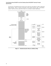
These functions include the following: • BIOS/ SPI Flash (4 MB) • Local APIC (19 MB) • Direct Media Interface (40 MB) • Front side bus interrupts (17 MB) • Internal graphics address ... 33 Typically the address space that is not possible to system address space being allocated for PCI Conventional add-in cards, PCI Express configuration space, BIOS (SPI Flash), and chipset overhead resides above the top of the installed memory due to use all of DRAM (total system memory). On a system that...
These functions include the following: • BIOS/ SPI Flash (4 MB) • Local APIC (19 MB) • Direct Media Interface (40 MB) • Front side bus interrupts (17 MB) • Internal graphics address ... 33 Typically the address space that is not possible to system address space being allocated for PCI Conventional add-in cards, PCI Express configuration space, BIOS (SPI Flash), and chipset overhead resides above the top of the installed memory due to use all of DRAM (total system memory). On a system that...
Product Specification
Page 34
Figure 7. All installed system memory can be used will vary based on add-in cards and BIOS settings. Detailed System Memory Address Map 34 Intel Desktop Board D425KT and Intel Desktop Board D425KTW Technical Product Specification The amount of installed memory that can be used when there is no overlap of the system memory map. Figure 7 shows a schematic of system addresses.
Figure 7. All installed system memory can be used will vary based on add-in cards and BIOS settings. Detailed System Memory Address Map 34 Intel Desktop Board D425KT and Intel Desktop Board D425KTW Technical Product Specification The amount of installed memory that can be used when there is no overlap of the system memory map. Figure 7 shows a schematic of system addresses.

Product Specification
Page 35
EFFFF C8000 - Video memory and BIOS Extended BIOS data (movable by memory manager software) Extended conventional memory Conventional memory 35 Dependent on video adapter used. FFFFF 896 K - 960 K 800 K - 896 K E0000 - C7FFF 9FC00 - ...9FFFF 80000 - 9FBFF 00000 - 7FFFF Size 4095 MB 64 KB 64 KB 96 KB 160 KB 1 KB 127 KB 512 KB Description Extended memory Runtime BIOS Reserved Potential available high DOS memory (open to the PCI bus). Technical Reference Table 9 lists the system memory map. DFFFF 640 K - 800 K 639 K - 640 K 512...
EFFFF C8000 - Video memory and BIOS Extended BIOS data (movable by memory manager software) Extended conventional memory Conventional memory 35 Dependent on video adapter used. FFFFF 896 K - 960 K 800 K - 896 K E0000 - C7FFF 9FC00 - ...9FFFF 80000 - 9FBFF 00000 - 7FFFF Size 4095 MB 64 KB 64 KB 96 KB 160 KB 1 KB 127 KB 512 KB Description Extended memory Runtime BIOS Reserved Potential available high DOS memory (open to the PCI bus). Technical Reference Table 9 lists the system memory map. DFFFF 640 K - 800 K 639 K - 640 K 512...

Product Specification
Page 47
... color state options. 2.2.2.4.4 Power Switch Header Pins 6 and 8 can be connected to a momentary single pole, single throw (SPST) type switch that can be modified through BIOS setup. When the switch is closed, the board resets and runs the POST. 2.2.2.4.3 Power/Sleep LED Header Pins 2 and 4 can be connected to internal debounce...
... color state options. 2.2.2.4.4 Power Switch Header Pins 6 and 8 can be connected to a momentary single pole, single throw (SPST) type switch that can be modified through BIOS setup. When the switch is closed, the board resets and runs the POST. 2.2.2.4.3 Power/Sleep LED Header Pins 2 and 4 can be connected to internal debounce...

Product Specification
Page 49
Otherwise, the board could be damaged. Figure 14 shows the location of the BIOS Configuration Jumper Block 49 Location of the jumper block. Table 26 lists the jumper settings for the three modes: normal, configure, and recovery. Figure 14. The jumper determines the BIOS Setup program's mode. Always turn off the power and unplug the power cord from the computer before changing a jumper setting. Technical Reference 2.3 BIOS Configuration Jumper Block CAUTION Do not move the jumper with the power on.
Otherwise, the board could be damaged. Figure 14 shows the location of the BIOS Configuration Jumper Block 49 Location of the jumper block. Table 26 lists the jumper settings for the three modes: normal, configure, and recovery. Figure 14. The jumper determines the BIOS Setup program's mode. Always turn off the power and unplug the power cord from the computer before changing a jumper setting. Technical Reference 2.3 BIOS Configuration Jumper Block CAUTION Do not move the jumper with the power on.

Product Specification
Page 50
BIOS Configuration Jumper Settings Function/Mode Jumper Setting Configuration Normal 1-2 The BIOS uses current configuration information and passwords for more information on BIOS recovery. 50 The BIOS attempts to recover the BIOS configuration. Intel Desktop Board D425KT and Intel Desktop Board D425KTW Technical Product Specification Table 26. The maintenance menu is displayed. Configure 2-3 Recovery None After the POST runs, Setup runs automatically. See Section 3.6.1 for booting.
BIOS Configuration Jumper Settings Function/Mode Jumper Setting Configuration Normal 1-2 The BIOS uses current configuration information and passwords for more information on BIOS recovery. 50 The BIOS attempts to recover the BIOS configuration. Intel Desktop Board D425KT and Intel Desktop Board D425KTW Technical Product Specification Table 26. The maintenance menu is displayed. Configure 2-3 Recovery None After the POST runs, Setup runs automatically. See Section 3.6.1 for booting.


