Product Guide
Page 4
... Processor ...38 Installing a 1 GHz Processor Fan Heatsink ...39 Removing the 1 GHz Processor Fan Heatsink ...42 Replacing the Battery ...43 Replacing the Battery on the D815EEA2 and D815EPEA2 Boards ...45 Replacing the Battery on the D815EFV and D815EPFV Boards ...46 Connecting the IDE Cable ...47 Setting the BIOS Configuration Jumper...48 Clearing the Passwords...49 3 Updating the BIOS Updating the BIOS with the Intel® Express BIOS Update Utility ...51 Updating the BIOS with the Intel® Flash Memory Update Utility ...51 Preparing for the Update ...51 Obtaining the BIOS Update File...
... Processor ...38 Installing a 1 GHz Processor Fan Heatsink ...39 Removing the 1 GHz Processor Fan Heatsink ...42 Replacing the Battery ...43 Replacing the Battery on the D815EEA2 and D815EPEA2 Boards ...45 Replacing the Battery on the D815EFV and D815EPFV Boards ...46 Connecting the IDE Cable ...47 Setting the BIOS Configuration Jumper...48 Clearing the Passwords...49 3 Updating the BIOS Updating the BIOS with the Intel® Express BIOS Update Utility ...51 Updating the BIOS with the Intel® Flash Memory Update Utility ...51 Preparing for the Update ...51 Obtaining the BIOS Update File...
Product Guide
Page 6
... the D815EFV and D815EPFV Boards...84 33. Board Differences ...9 Feature Summary ...9 Manufacturing Options...11 Supported Processors ...14 Processor and Memory Module Combinations...16 RJ-45 LAN Connector LEDs ...22 Jumper Settings for the D815EEA2 and D815EPEA2 Boards ...83 32. Add-in Board and Peripheral Interface Connectors for the BIOS Setup Program Modes...48 BIOS Setup Program Menu Bar...57 BIOS Setup Program Function Keys...58 Maintenance Menu ...58 Extended Configuration Submenu ...59 Main Menu...60 Advanced Menu...61 PCI Configuration Submenu ...62 Boot Configuration...
... the D815EFV and D815EPFV Boards...84 33. Board Differences ...9 Feature Summary ...9 Manufacturing Options...11 Supported Processors ...14 Processor and Memory Module Combinations...16 RJ-45 LAN Connector LEDs ...22 Jumper Settings for the D815EEA2 and D815EPEA2 Boards ...83 32. Add-in Board and Peripheral Interface Connectors for the BIOS Setup Program Modes...48 BIOS Setup Program Menu Bar...57 BIOS Setup Program Function Keys...58 Maintenance Menu ...58 Extended Configuration Submenu ...59 Main Menu...60 Advanced Menu...61 PCI Configuration Submenu ...62 Boot Configuration...

Product Guide
Page 12
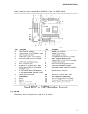
... (optional SMSC LPC47M142 I J K L M N O P CNR connector (optional) Analog Devices Inc. A B C DE F G H I J EE K DD CC BB AA L M Y Z X W V U T S R Q P O N OM11629 Item Description Item Description A B C D E F G H I /O controller) Serial port B connector SCSI hard drive activity LED connector Front panel switch/LED connector Chassis intrusion connector Alternate front panel power LED connector Chassis fan connector (fan 2, tach) BIOS configuration jumper block Battery WOL technology connector (optional) Front panel USB connector (optional) PCI bus add-in card connectors Figure...
... (optional SMSC LPC47M142 I J K L M N O P CNR connector (optional) Analog Devices Inc. A B C DE F G H I J EE K DD CC BB AA L M Y Z X W V U T S R Q P O N OM11629 Item Description Item Description A B C D E F G H I /O controller) Serial port B connector SCSI hard drive activity LED connector Front panel switch/LED connector Chassis intrusion connector Alternate front panel power LED connector Chassis fan connector (fan 2, tach) BIOS configuration jumper block Battery WOL technology connector (optional) Front panel USB connector (optional) PCI bus add-in card connectors Figure...
Product Guide
Page 13
...the D815EFV and D815EPFV boards. AD1885 audio codec AGP universal connector ATAPI-style auxiliary line in card connectors Figure 2. A B C DE F G H I J EE K DD CC BB AA Z X Y W V U T S R Q P O N L M OM11630 Item Description Item Description A B C D E F G H I /O controller) Serial port B connector SCSI hard drive activity LED connector Front panel switch/LED connector Alternate front panel power LED connector Chassis intrusion connector Chassis fan connector (fan 2, tach) BIOS configuration jumper block WOL technology connector (optional) Front panel USB connector (optional) PCI bus...
...the D815EFV and D815EPFV boards. AD1885 audio codec AGP universal connector ATAPI-style auxiliary line in card connectors Figure 2. A B C DE F G H I J EE K DD CC BB AA Z X Y W V U T S R Q P O N L M OM11630 Item Description Item Description A B C D E F G H I /O controller) Serial port B connector SCSI hard drive activity LED connector Front panel switch/LED connector Alternate front panel power LED connector Chassis intrusion connector Chassis fan connector (fan 2, tach) BIOS configuration jumper block WOL technology connector (optional) Front panel USB connector (optional) PCI bus...
Product Guide
Page 14
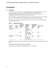
... or D815EFV/D815EPFV Specification Update for the latest list of unsupported processors can damage the board, the processor, and the power supply. The boards support a single Intel Pentium III processor or Intel Celeron processor above 533 MHz. The boards support the processors listed in Table 4. The processor connects to the Intel desktop board Web site at: http://support.intel.com/support/motherboards/desktop/ For instructions on processor support for theD815EEA2, D815EPEA2, D815EFV, and D815EPFV boards. Processor Type Intel Pentium III processors Supported Processors Socket Type FC...
... or D815EFV/D815EPFV Specification Update for the latest list of unsupported processors can damage the board, the processor, and the power supply. The boards support a single Intel Pentium III processor or Intel Celeron processor above 533 MHz. The boards support the processors listed in Table 4. The processor connects to the Intel desktop board Web site at: http://support.intel.com/support/motherboards/desktop/ For instructions on processor support for theD815EEA2, D815EPEA2, D815EFV, and D815EPFV boards. Processor Type Intel Pentium III processors Supported Processors Socket Type FC...

Product Guide
Page 17
... connector (D815EFV) Support for the Low Pin Count (LPC) interface Integrated IDE controller (supports Ultra DMA mode and ATA-66/100 mode) Integrated LAN media access controller Support for CNR Support for USB Power management logic (ACPI Rev 2.0 compliant) Support for the System Management Bus routed to: PCI bus connector 2 S5 wake from PCI bus connector 2 Real-Time Clock (with 256-byte battery backed CMOS RAM) AC '97 digital link for: AC '97 2.1 compliant Logic for audio in, audio...
... connector (D815EFV) Support for the Low Pin Count (LPC) interface Integrated IDE controller (supports Ultra DMA mode and ATA-66/100 mode) Integrated LAN media access controller Support for CNR Support for USB Power management logic (ACPI Rev 2.0 compliant) Support for the System Management Bus routed to: PCI bus connector 2 S5 wake from PCI bus connector 2 Real-Time Clock (with 256-byte battery backed CMOS RAM) AC '97 digital link for: AC '97 2.1 compliant Logic for audio in, audio...

Product Guide
Page 18
...) support Serial IRQ interface compatible with serialized IRQ support for PCI systems PS/2-style mouse and keyboard interfaces Interface for one 1.2 MB, 1.44 MB, or 2.88 MB diskette drive Intelligent power management, including a programmable wake up to be compatible with UHCI. 18 The desktop board supports the Universal Host Controller Interface (UHCI) and takes advantage of -day clock and 100-year calendar. You can connect two USB peripheral devices...
...) support Serial IRQ interface compatible with serialized IRQ support for PCI systems PS/2-style mouse and keyboard interfaces Interface for one 1.2 MB, 1.44 MB, or 2.88 MB diskette drive Intelligent power management, including a programmable wake up to be compatible with UHCI. 18 The desktop board supports the Universal Host Controller Interface (UHCI) and takes advantage of -day clock and 100-year calendar. You can connect two USB peripheral devices...

Product Guide
Page 20
... ACPI 2.0 (driver dependent) 3-D stereo enhancement Intel 82801BA I/O Controller Hub (ICH2) Analog Devices Inc. Poor audio quality may occur if passive (non-amplified) speakers are connected to power headphones or amplified speakers only. PCI Auto Configuration If you install a PCI add-in Chapter 3. You do not need to run the BIOS Setup program after you install a PCI add-in board in your computer, the IDE auto-configuration utility in board. Intel Desktop Boards D815EEA2, D815EPEA2, D815EFV, and D815EPFV Product Guide Audio Subsystem...
... ACPI 2.0 (driver dependent) 3-D stereo enhancement Intel 82801BA I/O Controller Hub (ICH2) Analog Devices Inc. Poor audio quality may occur if passive (non-amplified) speakers are connected to power headphones or amplified speakers only. PCI Auto Configuration If you install a PCI add-in Chapter 3. You do not need to run the BIOS Setup program after you install a PCI add-in board in your computer, the IDE auto-configuration utility in board. Intel Desktop Boards D815EEA2, D815EPEA2, D815EFV, and D815EPFV Product Guide Audio Subsystem...
Product Guide
Page 23
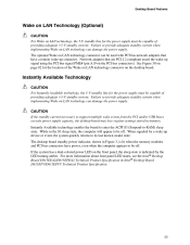
... the LED turning amber. The desktop board standby power indicator, shown in Figure 3, is indicated by a wake-up signal using the PCI bus signal PME# (pin A19 on the PCI bus connectors). Desktop Board Features Wake on LAN Technology (Optional) CAUTION For Wake on LAN technology, the 5-V standby line for the location of the Wake on LAN technology connector on the desktop board. Instantly Available Technology CAUTION For Instantly Available technology, the 5-V standby line for the power supply must be off . Failure to -RAM) sleep state...
... the LED turning amber. The desktop board standby power indicator, shown in Figure 3, is indicated by a wake-up signal using the PCI bus signal PME# (pin A19 on the PCI bus connectors). Desktop Board Features Wake on LAN Technology (Optional) CAUTION For Wake on LAN technology, the 5-V standby line for the location of the Wake on LAN technology connector on the desktop board. Instantly Available Technology CAUTION For Instantly Available technology, the 5-V standby line for the power supply must be off . Failure to -RAM) sleep state...

Product Guide
Page 25
... as model, serial number, installed options, and configuration information. If such a station is not available, you can continue to operate even though the front panel power button is off. 25 2 Installing and Replacing Desktop Board Components This chapter tells you how to Install and remove memory Install and remove the AGP card retention mechanism (included) Install and remove AGP and GPA cards Install the I/O shield Install the desktop board Install and remove the processor Replace the battery Connect the IDE cable Set the BIOS configuration jumper Before...
... as model, serial number, installed options, and configuration information. If such a station is not available, you can continue to operate even though the front panel power button is off. 25 2 Installing and Replacing Desktop Board Components This chapter tells you how to Install and remove memory Install and remove the AGP card retention mechanism (included) Install and remove AGP and GPA cards Install the I/O shield Install the desktop board Install and remove the processor Replace the battery Connect the IDE cable Set the BIOS configuration jumper Before...

Product Guide
Page 48
...Block Location (the D815EEA2 Board Is Shown) This three-pin jumper block, shown in Figure 26, enables all desktop board configurations to recover the BIOS configuration. Table 7. The BIOS attempts to be done in unreliable computer operation. 3 1 J9G2 OM11628 Figure 26. A recovery diskette is displayed. Normal Configure Recovery Jumper Settings for the BIOS Setup Program Modes Jumper Setting 1-2 2-3 None 3 1 Function/Mode Configuration The BIOS uses current configuration information and passwords for the Setup program modes. Intel Desktop Boards D815EEA2, D815EPEA2, D815EFV...
...Block Location (the D815EEA2 Board Is Shown) This three-pin jumper block, shown in Figure 26, enables all desktop board configurations to recover the BIOS configuration. Table 7. The BIOS attempts to be done in unreliable computer operation. 3 1 J9G2 OM11628 Figure 26. A recovery diskette is displayed. Normal Configure Recovery Jumper Settings for the BIOS Setup Program Modes Jumper Setting 1-2 2-3 None 3 1 Function/Mode Configuration The BIOS uses current configuration information and passwords for the Setup program modes. Intel Desktop Boards D815EEA2, D815EPEA2, D815EFV...

Product Guide
Page 49
... outlet or power adapter). 3. Replace the cover, plug in the computer, and turn on pins 2-3 as shown below . 3 1 6. Remove the computer cover. 4. Setup displays the maintenance menu. 8. Press to boot. 7. To restore normal operation, place the jumper on the computer. 49 The computer starts the Setup program. Turn off all peripheral devices connected to normal mode. 1. Installing and Replacing Desktop Board Components Clearing the Passwords This procedure assumes that you confirm clearing the password. Turn off...
... outlet or power adapter). 3. Replace the cover, plug in the computer, and turn on pins 2-3 as shown below . 3 1 6. Remove the computer cover. 4. Setup displays the maintenance menu. 8. Press to boot. 7. To restore normal operation, place the jumper on the computer. 49 The computer starts the Setup program. Turn off all peripheral devices connected to normal mode. 1. Installing and Replacing Desktop Board Components Clearing the Passwords This procedure assumes that you confirm clearing the password. Turn off...

Product Guide
Page 58
... the BIOS Setup program Exits the menu BIOS Setup Program Function Key or or Maintenance Menu This menu is used to clear passwords, to access the extended configuration submenu, and to access processor information. See page 48 for menu screens. To access this menu in the configure mode. Invokes the Extended Configuration submenu. Maintenance Main Advanced Security Power Boot Exit Extended Configuration Table 10. Feature Maintenance Menu Options • Yes (default) • No Description Clears the user and administrative passwords. Displays CPU's Stepping...
... the BIOS Setup program Exits the menu BIOS Setup Program Function Key or or Maintenance Menu This menu is used to clear passwords, to access the extended configuration submenu, and to access processor information. See page 48 for menu screens. To access this menu in the configure mode. Invokes the Extended Configuration submenu. Maintenance Main Advanced Security Power Boot Exit Extended Configuration Table 10. Feature Maintenance Menu Options • Yes (default) • No Description Clears the user and administrative passwords. Displays CPU's Stepping...

Product Guide
Page 59
Maintenance Main Advanced Security Power Boot Exit Extended Configuration The submenu represented by the processor. This submenu becomes available when User Defined is for applications not supporting Write Combining. Selects Uncacheable Speculative Write-Combining (USWC) video memory cache mode. Full 32 byte contents of clock cycles required to memory as : "Extended Menu: Used." This setting identifies the video memory range as uncacheable by Table 11 is selected under...
Maintenance Main Advanced Security Power Boot Exit Extended Configuration The submenu represented by the processor. This submenu becomes available when User Defined is for applications not supporting Write Combining. Selects Uncacheable Speculative Write-Combining (USWC) video memory cache mode. Full 32 byte contents of clock cycles required to memory as : "Extended Menu: Used." This setting identifies the video memory range as uncacheable by Table 11 is selected under...
Product Guide
Page 60
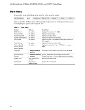
...RAM Total Memory Memory Bank 0 Memory Bank 1 Memory Bank 2 Language Processor Serial Number System Time System Date Main Menu Options No options No options No options No options No options No options No options Description Displays the version of RAM. Displays processor speed. Displays the total amount of the BIOS. Maintenance Main Advanced Security Power Boot Exit Table 12 describes the Main Menu. Displays the system bus frequency. Displays the amount and type of the screen. Intel Desktop Boards D815EEA2, D815EPEA2, D815EFV, and D815EPFV Product Guide Main Menu To access...
...RAM Total Memory Memory Bank 0 Memory Bank 1 Memory Bank 2 Language Processor Serial Number System Time System Date Main Menu Options No options No options No options No options No options No options No options Description Displays the version of RAM. Displays processor speed. Displays the total amount of the BIOS. Maintenance Main Advanced Security Power Boot Exit Table 12 describes the Main Menu. Displays the system bus frequency. Displays the amount and type of the screen. Intel Desktop Boards D815EEA2, D815EPEA2, D815EFV, and D815EPFV Product Guide Main Menu To access...

Product Guide
Page 66
...connected IDE device. Intel Desktop Boards D815EEA2, D815EPEA2, D815EFV, and D815EPFV Product Guide IDE Configuration Submenu To access this submenu, select Advanced on the menu bar, then IDE Configuration. Both enables both IDE controllers. Secondary IDE Slave No options 66 Feature IDE Controller IDE Configuration Submenu Options • Disabled • Primary • Secondary • Both (default) Description Specifies the integrated IDE controller. When selected, displays the Secondary IDE Slave submenu. Maintenance Main Advanced Security Power Boot Exit PCI Configuration Boot...
...connected IDE device. Intel Desktop Boards D815EEA2, D815EPEA2, D815EFV, and D815EPFV Product Guide IDE Configuration Submenu To access this submenu, select Advanced on the menu bar, then IDE Configuration. Both enables both IDE controllers. Secondary IDE Slave No options 66 Feature IDE Controller IDE Configuration Submenu Options • Disabled • Primary • Secondary • Both (default) Description Specifies the integrated IDE controller. When selected, displays the Secondary IDE Slave submenu. Maintenance Main Advanced Security Power Boot Exit PCI Configuration Boot...

Product Guide
Page 67
... 16 Sectors (default) Auto (default) 0 1 2 3 4 Description Displays the type of the drive. Auto fills-in capabilities from the hard disk drive to memory. Enables or disables LBA mode control. Table 18. Maximum Capacity LBA Mode Control Multi-Sector Transfers Displays the capacity of drive installed. Specifies the PIO mode. continued 67 Specifies the IDE configuration mode for optimum setting. Maintenance Main Advanced Security Power Boot Exit PCI Configuration Boot Configuration Peripheral Configuration IDE Configuration Primary IDE Master Primary IDE Slave Secondary...
... 16 Sectors (default) Auto (default) 0 1 2 3 4 Description Displays the type of the drive. Auto fills-in capabilities from the hard disk drive to memory. Enables or disables LBA mode control. Table 18. Maximum Capacity LBA Mode Control Multi-Sector Transfers Displays the capacity of drive installed. Specifies the PIO mode. continued 67 Specifies the IDE configuration mode for optimum setting. Maintenance Main Advanced Security Power Boot Exit PCI Configuration Boot Configuration Peripheral Configuration IDE Configuration Primary IDE Master Primary IDE Slave Secondary...

Product Guide
Page 74
... the menu bar at boot time. • Enabled No options No options No options No options Specifies the boot sequence from the available ATAPI CD-ROM drives. 74 Intel Desktop Boards D815EEA2, D815EPEA2, D815EFV, and D815EPFV Product Guide Boot Menu To access this menu, select Boot from the available removable devices. Enables the computer to set the boot features and the boot sequence. Feature Quiet Boot Boot Menu Options • Disabled • Enabled (default) Description Disabled displays normal POST messages. Table 26. Enabled displays OEM graphic instead of the screen.
... the menu bar at boot time. • Enabled No options No options No options No options Specifies the boot sequence from the available ATAPI CD-ROM drives. 74 Intel Desktop Boards D815EEA2, D815EPEA2, D815EFV, and D815EPFV Product Guide Boot Menu To access this menu, select Boot from the available removable devices. Enables the computer to set the boot features and the boot sequence. Feature Quiet Boot Boot Menu Options • Disabled • Enabled (default) Description Disabled displays normal POST messages. Table 26. Enabled displays OEM graphic instead of the screen.

Product Guide
Page 77
... factory defaults. Using the Setup Program ATAPI CDROM Drives To access this memory is corrupted, the BIOS reads the custom defaults. Table 31. Exits without exiting Setup. Maintenance Main Advanced Security Power Boot Exit The menu represented in the BIOS Setup program. Loads the factory default values for setting ATAPI CD-ROM drives. Maintenance Main Advanced Security Power Boot Exit Boot Device Priority Hard Disk Drives Removeable Devices ATAPI CDROM Drives The submenu represented in CMOS SRAM. If this menu, select Boot from flash memory. Discard Changes...
... factory defaults. Using the Setup Program ATAPI CDROM Drives To access this memory is corrupted, the BIOS reads the custom defaults. Table 31. Exits without exiting Setup. Maintenance Main Advanced Security Power Boot Exit The menu represented in the BIOS Setup program. Loads the factory default values for setting ATAPI CD-ROM drives. Maintenance Main Advanced Security Power Boot Exit Boot Device Priority Hard Disk Drives Removeable Devices ATAPI CDROM Drives The submenu represented in CMOS SRAM. If this menu, select Boot from flash memory. Discard Changes...

Product Guide
Page 80
.../2 keyboard, purple USB port 0 USB port 1 Parallel port, burgundy VGA port, blue (D815EEA2 and D815EFV only) Serial port A, teal H I J K L M RJ-45 LAN connector with LED display (optional) USB port 2 USB port 3 Mic in, pink Audio line out, lime green Audio line in compliance with PC 99 recommendations. Poor audio quality may occur if passive (non-amplified) speakers are color-coded in , light blue Figure 28. Intel Desktop Boards D815EEA2, D815EPEA2, D815EFV, and D815EPFV Product Guide Back Panel Connectors Figure 28 shows the back panel connectors...
.../2 keyboard, purple USB port 0 USB port 1 Parallel port, burgundy VGA port, blue (D815EEA2 and D815EFV only) Serial port A, teal H I J K L M RJ-45 LAN connector with LED display (optional) USB port 2 USB port 3 Mic in, pink Audio line out, lime green Audio line in compliance with PC 99 recommendations. Poor audio quality may occur if passive (non-amplified) speakers are color-coded in , light blue Figure 28. Intel Desktop Boards D815EEA2, D815EPEA2, D815EFV, and D815EPFV Product Guide Back Panel Connectors Figure 28 shows the back panel connectors...


