
Product Specification
Page 5
...13 1.2.3 Board Layouts 14 1.2.4 Block Diagram 16 1.3 Online Support ...17 1.4 Operating System Support 17 1.5 Design Specifications 18 1.6 Processor ...21 1.7 System Memory ...22 1.7.1 Memory Configurations 24 1.8 Intel® 865PE Chipset 29 1.8.1 Universal 0.8 V / 1.5 V AGP 3.0 Connector 30 1.8.2 USB...30 1.8.3 IDE Support 31 1.8.4... Diskette Drive Controller 33 1.9.4 Keyboard and Mouse Interface 34 1.10 Audio Subsystem...34 1.10.1 Audio Subsystem Software 34 1.10.2 Intel® Flex 6 Audio Subsystem 34 1.10.3 Audio Connectors 36 1.11 LAN Subsystem...37 1.11.1 10/100 Mbits/sec LAN...
...13 1.2.3 Board Layouts 14 1.2.4 Block Diagram 16 1.3 Online Support ...17 1.4 Operating System Support 17 1.5 Design Specifications 18 1.6 Processor ...21 1.7 System Memory ...22 1.7.1 Memory Configurations 24 1.8 Intel® 865PE Chipset 29 1.8.1 Universal 0.8 V / 1.5 V AGP 3.0 Connector 30 1.8.2 USB...30 1.8.3 IDE Support 31 1.8.4... Diskette Drive Controller 33 1.9.4 Keyboard and Mouse Interface 34 1.10 Audio Subsystem...34 1.10.1 Audio Subsystem Software 34 1.10.2 Intel® Flex 6 Audio Subsystem 34 1.10.3 Audio Connectors 36 1.11 LAN Subsystem...37 1.11.1 10/100 Mbits/sec LAN...
Product Specification
Page 9
... ...94 50. Peripheral Configuration Submenu 100 55. SATA/PATA Submenus 105 57. USB Configuration Submenu 109 61. Fan Control Configuration Submenu 112 ix Contents 15. Processor Fan Connector 63 26. Front Chassis Fan Connector 64 28. Front Panel Connector 69 33. Product Certification Markings 84 45. Auxiliary Line In Connector 61...
... ...94 50. Peripheral Configuration Submenu 100 55. SATA/PATA Submenus 105 57. USB Configuration Submenu 109 61. Fan Control Configuration Submenu 112 ix Contents 15. Processor Fan Connector 63 26. Front Chassis Fan Connector 64 28. Front Panel Connector 69 33. Product Certification Markings 84 45. Auxiliary Line In Connector 61...
Product Specification
Page 11
... Board D865PERC. 1 Product Description What This Chapter Contains 1.1 Board Differences...11 1.2 Overview ...12 1.3 Online Support ...17 1.4 Operating System Support 17 1.5 Design Specifications 18 1.6 Processor ...21 1.7 System Memory ...22 1.8 Intel® 865PE Chipset 29 1.9 I/O Controller ...32 1.10 Audio Subsystem...34 1.11 LAN Subsystem...37 1.12 Hardware Management Subsystem 39 1.13 Power Management 42...
... Board D865PERC. 1 Product Description What This Chapter Contains 1.1 Board Differences...11 1.2 Overview ...12 1.3 Online Support ...17 1.4 Operating System Support 17 1.5 Design Specifications 18 1.6 Processor ...21 1.7 System Memory ...22 1.8 Intel® 865PE Chipset 29 1.9 I/O Controller ...32 1.10 Audio Subsystem...34 1.11 LAN Subsystem...37 1.12 Hardware Management Subsystem 39 1.13 Power Management 42...
Product Specification
Page 12
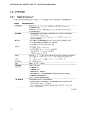
...by 9.60 inches [243.84 millimeters by 243.84 millimeters]) • Support for an Intel® Pentium® 4 processor in an mPGA478 socket with a 400/533/800 MHz system bus • Support for an Intel® Celeron® processor in an mPGA478 socket with a 400 MHz system bus • Four 184-pin DDR... SDRAM Dual Inline Memory Module (DIMM) sockets • Support for DDR 400, DDR 333, and DDR 266 • Support for up to 4 GB of system memory Intel® 865PE Chipset...
...by 9.60 inches [243.84 millimeters by 243.84 millimeters]) • Support for an Intel® Pentium® 4 processor in an mPGA478 socket with a 400/533/800 MHz system bus • Support for an Intel® Celeron® processor in an mPGA478 socket with a 400 MHz system bus • Four 184-pin DDR... SDRAM Dual Inline Memory Module (DIMM) sockets • Support for DDR 400, DDR 333, and DDR 266 • Support for up to 4 GB of system memory Intel® 865PE Chipset...

Product Specification
Page 16
... the boards. = connector or socket Parallel ATA IDE Connectors (2) Parallel ATA IDE Interface mPGA478 System Bus Processor Socket (400/533/800 MHz) LAN Connector Gigabit LAN PLC (Optional) CSA Interface AGP Interface Universal 0.8/ 1.5 V AGP 3.0 Connector Intel 82865PE Memory Controller Hub (MCH) AHA Bus Channel A DIMMs (2) Channel B DIMMs (2) Dual-Channel Memory Bus SMBus...
... the boards. = connector or socket Parallel ATA IDE Connectors (2) Parallel ATA IDE Interface mPGA478 System Bus Processor Socket (400/533/800 MHz) LAN Connector Gigabit LAN PLC (Optional) CSA Interface AGP Interface Universal 0.8/ 1.5 V AGP 3.0 Connector Intel 82865PE Memory Controller Hub (MCH) AHA Bus Channel A DIMMs (2) Channel B DIMMs (2) Dual-Channel Memory Bus SMBus...
Product Specification
Page 17
...systems: • Microsoft Windows* XP • Windows ME • Windows 2000 • Windows 98 SE For information about ... Intel Desktop Boards D865PERC and D865PESO under "Desktop Board Products" or "Desktop Board Support" Available configurations for the Desktop Board D865PERC Available ...Desktop Board D865PESO Processor data sheets ICH5 addressing Custom splash screens Audio software and utilities LAN software and drivers Visit this World Wide Web site: http://www.intel.com/design/motherbd http://support.intel.com/support/motherboards/desktop http://developer.intel.com/design/motherbd...
...systems: • Microsoft Windows* XP • Windows ME • Windows 2000 • Windows 98 SE For information about ... Intel Desktop Boards D865PERC and D865PESO under "Desktop Board Products" or "Desktop Board Support" Available configurations for the Desktop Board D865PERC Available ...Desktop Board D865PESO Processor data sheets ICH5 addressing Custom splash screens Audio software and utilities LAN software and drivers Visit this World Wide Web site: http://www.intel.com/design/motherbd http://support.intel.com/support/motherboards/desktop http://developer.intel.com/design/motherbd...
Product Specification
Page 21
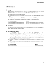
... memory speed combinations. The board is designed to support the following: • Intel Pentium 4 processors in an mPGA478 processor socket with a 400/533/800 MHz system bus • Intel Celeron processors in an mPGA478 processor socket with a standard ATX power supply. • Refer to Table 5 on...78) for the most up-to-date list of supported processors. The board will not boot with a 400 MHz system bus See the Intel web site listed below for important information when using an Intel Pentium 4 processor operating above . For information about Power supply connectors Refer ...
... memory speed combinations. The board is designed to support the following: • Intel Pentium 4 processors in an mPGA478 processor socket with a 400/533/800 MHz system bus • Intel Celeron processors in an mPGA478 processor socket with a standard ATX power supply. • Refer to Table 5 on...78) for the most up-to-date list of supported processors. The board will not boot with a 400 MHz system bus See the Intel web site listed below for important information when using an Intel Pentium 4 processor operating above . For information about Power supply connectors Refer ...
Product Specification
Page 22
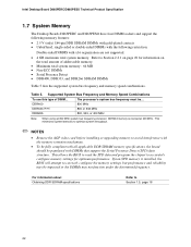
... should be populated with x16 organization are not supported. • 4 GB maximum total system memory. DDR400 DDR333 (Note) DDR266 The processor's system bus frequency must be impacted or the DIMMs may not function under the determined frequency. This minimizes system latencies to optimize system ...800 or 533 MHz 800, 533, or 400 MHz Note: When using an 800 MHz system bus frequency processor, DDR333 memory is clocked at 320 MHz. Intel Desktop Board D865PERC/D865PESO Technical Product Specification 1.7 System Memory The Desktop Boards D865PERC and D865PESO have four DIMM sockets...
... should be populated with x16 organization are not supported. • 4 GB maximum total system memory. DDR400 DDR333 (Note) DDR266 The processor's system bus frequency must be impacted or the DIMMs may not function under the determined frequency. This minimizes system latencies to optimize system ...800 or 533 MHz 800, 533, or 400 MHz Note: When using an 800 MHz system bus frequency processor, DDR333 memory is clocked at 320 MHz. Intel Desktop Board D865PERC/D865PESO Technical Product Specification 1.7 System Memory The Desktop Boards D865PERC and D865PESO have four DIMM sockets...

Product Specification
Page 31
... location of the Parallel ATA IDE connectors on the D865PESO board The location of the following modes: • Programmed I/O (PIO): processor controls data transfer. • 8237-style DMA: DMA offloads the processor, supporting transfer rates of up to 16 MB/sec. • Ultra DMA: DMA protocol on IDE bus supporting host and...
... location of the Parallel ATA IDE connectors on the D865PESO board The location of the following modes: • Programmed I/O (PIO): processor controls data transfer. • 8237-style DMA: DMA offloads the processor, supporting transfer rates of up to 16 MB/sec. • Ultra DMA: DMA protocol on IDE bus supporting host and...

Product Specification
Page 39
... established. LAN link is not established. The computer is selected. 1.11.3 LAN Subsystem Software LAN software and drivers are available from Intel's World Wide Web site. The Desktop Board has several hardware management features, including the following: • Fan monitoring and control ...and fan control ASIC include: • Internal ambient temperature sensor • Two remote thermal diode sensors for direct monitoring of processor temperature and ambient temperature sensing • Power supply monitoring of the fan connectors and sensors for thermal monitoring Refer to detect ...
... established. LAN link is not established. The computer is selected. 1.11.3 LAN Subsystem Software LAN software and drivers are available from Intel's World Wide Web site. The Desktop Board has several hardware management features, including the following: • Fan monitoring and control ...and fan control ASIC include: • Internal ambient temperature sensor • Two remote thermal diode sensors for direct monitoring of processor temperature and ambient temperature sensing • Power supply monitoring of the fan connectors and sensors for thermal monitoring Refer to detect ...
Product Specification
Page 40
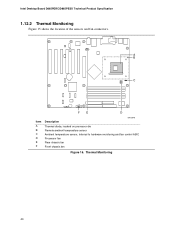
Intel Desktop Board D865PERC/D865PESO Technical Product Specification 1.12.2 Thermal Monitoring Figure 15 shows the location of the sensors and fan connectors. 31 A B 1 C 3 13 FE D Item A B C D E F OM15940 Description Thermal diode, located on processor die Remote ambient temperature sensor Ambient temperature sensor, internal to hardware monitoring and fan control ASIC Processor fan Rear chassis fan Front chassis fan Figure 15. Thermal Monitoring 40
Intel Desktop Board D865PERC/D865PESO Technical Product Specification 1.12.2 Thermal Monitoring Figure 15 shows the location of the sensors and fan connectors. 31 A B 1 C 3 13 FE D Item A B C D E F OM15940 Description Thermal diode, located on processor die Remote ambient temperature sensor Ambient temperature sensor, internal to hardware monitoring and fan control ASIC Processor fan Rear chassis fan Front chassis fan Figure 15. Thermal Monitoring 40

Product Specification
Page 43
Devices that are being used in the system. 43 Power States and Targeted System Power Global States Sleeping States Processor States Device States Targeted System Power (Note 1) G0 - Suspend to disk. Context saved to RAM. C0 - working S1 - device specification specific. Notes... states. no power except for wake-up logic, except when provided by the Desktop Boards D865PERC and D865PESO along with the associated system power targets. Processor stopped S3 - Context not saved. stop grant No power No power No power D0 - D3 - D3 - D3 - S4 - Total system ...
Devices that are being used in the system. 43 Power States and Targeted System Power Global States Sleeping States Processor States Device States Targeted System Power (Note 1) G0 - Suspend to disk. Context saved to RAM. C0 - working S1 - device specification specific. Notes... states. no power except for wake-up logic, except when provided by the Desktop Boards D865PERC and D865PESO along with the associated system power targets. Processor stopped S3 - Context not saved. stop grant No power No power No power D0 - D3 - D3 - D3 - S4 - Total system ...

Product Specification
Page 46
...PCI bus PME# signal for a system or chassis fan. • Fan is on or off as needed. Fan Connector Function/Operation Connector Processor fan Front chassis fan Rear chassis fan Description • +12 V DC connection for the power supply must be capable of the hardware monitoring ...is off as needed . • +12 V DC connection for thermal monitoring The signal names of the fan connectors. Table 13. Intel Desktop Board D865PERC/D865PESO Technical Product Specification 1.13.2.2 Fan Connectors Table 13 summarizes the function/operation of the fan connectors Refer to provide ...
...PCI bus PME# signal for a system or chassis fan. • Fan is on or off as needed. Fan Connector Function/Operation Connector Processor fan Front chassis fan Rear chassis fan Description • +12 V DC connection for the power supply must be capable of the hardware monitoring ...is off as needed . • +12 V DC connection for thermal monitoring The signal names of the fan connectors. Table 13. Intel Desktop Board D865PERC/D865PESO Technical Product Specification 1.13.2.2 Fan Connectors Table 13 summarizes the function/operation of the fan connectors Refer to provide ...
Product Specification
Page 59
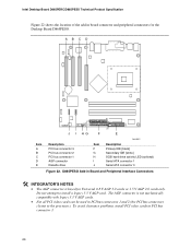
... are connected to this output. 2.8.2 Internal I/O Connectors The internal I/O connectors are identified as PCI slot #x, starting with the slot closest to the processor. PCI add-in boards and peripheral interfaces (see page 62) Fans [3] ATX12V power Main power Chassis ...is keyed for Universal 0.8 V AGP 3.0 cards or 1.5 V AGP 2.0 cards only. The AGP slot is not mechanically compatible with respect to processor location on the Desktop Board D865PESO). The AGP connector is not numbered. Do not install a legacy 3.3 V AGP card. The SMBus is ...
... are connected to this output. 2.8.2 Internal I/O Connectors The internal I/O connectors are identified as PCI slot #x, starting with the slot closest to the processor. PCI add-in boards and peripheral interfaces (see page 62) Fans [3] ATX12V power Main power Chassis ...is keyed for Universal 0.8 V AGP 3.0 cards or 1.5 V AGP 2.0 cards only. The AGP slot is not mechanically compatible with respect to processor location on the Desktop Board D865PESO). The AGP connector is not numbered. Do not install a legacy 3.3 V AGP card. The SMBus is ...

Product Specification
Page 62
... 2 +12 V 3 REAR_TACH_OUT 62 A B 1 3 12 34 1 3 113 20 11 1 FE D C Item A B C D E F Description Rear chassis fan +12 V power connector (ATX12V) Processor fan Main power Front chassis fan Chassis intrusion For more information see: Table 23 Table 24 Table 25 Table 26 Table 27 Table 28 OM15944... Figure 20. Power and Hardware Control Connectors Table 23. Intel Desktop Board D865PERC/D865PESO Technical Product Specification 2.8.2.3 Power and Hardware Control Connectors Figure 20 shows the location of the power and hardware...
... 2 +12 V 3 REAR_TACH_OUT 62 A B 1 3 12 34 1 3 113 20 11 1 FE D C Item A B C D E F Description Rear chassis fan +12 V power connector (ATX12V) Processor fan Main power Front chassis fan Chassis intrusion For more information see: Table 23 Table 24 Table 25 Table 26 Table 27 Table 28 OM15944... Figure 20. Power and Hardware Control Connectors Table 23. Intel Desktop Board D865PERC/D865PESO Technical Product Specification 2.8.2.3 Power and Hardware Control Connectors Figure 20 shows the location of the power and hardware...
Product Specification
Page 63
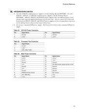
The board will not boot. • Do not use a standard ATX power supply. Processor Fan Connector Pin Signal Name 1 Control 2 +12 V 3 CPU_FAN_TACH Table 26. ATX12V Power Connector Pin Signal Name 1 Ground 3 +12 V Pin Signal Name 2 Ground 4 +12 V Table 25. ... Ground 18 No connect 19 +5 V 20 +5 V 63 ATX12V, SFX12V, and TFX12V power supplies have an additional power lead that provides required supplemental power for the processor. Technical Reference # INTEGRATOR'S NOTES • Use only ATX12V-compliant power supplies with the Desktop Board D865PESO.
The board will not boot. • Do not use a standard ATX power supply. Processor Fan Connector Pin Signal Name 1 Control 2 +12 V 3 CPU_FAN_TACH Table 26. ATX12V Power Connector Pin Signal Name 1 Ground 3 +12 V Pin Signal Name 2 Ground 4 +12 V Table 25. ... Ground 18 No connect 19 +5 V 20 +5 V 63 ATX12V, SFX12V, and TFX12V power supplies have an additional power lead that provides required supplemental power for the processor. Technical Reference # INTEGRATOR'S NOTES • Use only ATX12V-compliant power supplies with the Desktop Board D865PESO.
Product Specification
Page 66
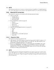
... Diskette drive Item F G H I J OM15957 Description Primary IDE [black] Secondary IDE [white] SCSI hard drive activity LED (optional) Serial ATA connector 1 Serial ATA connector 0 Figure 22. Intel Desktop Board D865PERC/D865PESO Technical Product Specification Figure 22 shows the location of the add-in PCI bus connector 3. 66 Do not attempt to the...
... Diskette drive Item F G H I J OM15957 Description Primary IDE [black] Secondary IDE [white] SCSI hard drive activity LED (optional) Serial ATA connector 1 Serial ATA connector 0 Figure 22. Intel Desktop Board D865PERC/D865PESO Technical Product Specification Figure 22 shows the location of the add-in PCI bus connector 3. 66 Do not attempt to the...

Product Specification
Page 73
... 35. The 3 maintenance menu is required. 73 Recovery None 1 The BIOS attempts to configure mode and the computer is powered-up, the BIOS compares the processor version and the microcode version in signals are disabled. 2.9.2 BIOS Setup Configuration Jumper Block The 3-pin jumper block determines the BIOS Setup program's mode. Technical...
... 35. The 3 maintenance menu is required. 73 Recovery None 1 The BIOS attempts to configure mode and the computer is powered-up, the BIOS compares the processor version and the microcode version in signals are disabled. 2.9.2 BIOS Setup Configuration Jumper Block The 3-pin jumper block determines the BIOS Setup program's mode. Technical...
Product Specification
Page 77
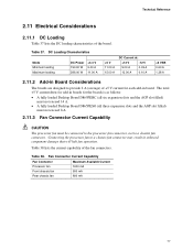
...mA 77 Technical Reference 2.11 Electrical Considerations 2.11.1 DC Loading Table 37 lists the DC loading characteristics of the fan connectors. Connecting the processor fan to a chassis fan connector may result in Board Considerations The boards are designed to provide 2 A (average) of +5 V current...all three expansion slots and the AGP slot filled) must not exceed 8 A. 2.11.3 Fan Connector Current Capability CAUTION The processor fan must be connected to the processor fan connector, not to a chassis fan connector. Table 38 lists the current capability of the board. Table 38. The...
...mA 77 Technical Reference 2.11 Electrical Considerations 2.11.1 DC Loading Table 37 lists the DC loading characteristics of the fan connectors. Connecting the processor fan to a chassis fan connector may result in Board Considerations The boards are designed to provide 2 A (average) of +5 V current...all three expansion slots and the AGP slot filled) must not exceed 8 A. 2.11.3 Fan Connector Current Capability CAUTION The processor fan must be connected to the processor fan connector, not to a chassis fan connector. Table 38 lists the current capability of the board. Table 38. The...

Product Specification
Page 78
... Power Supply Considerations CAUTION The +5 V standby line for use of an Intel Pentium 4 processor operating above 2.80 GHz Failure to ensure appropriate airflow may result in reduced performance of both the processor and/or voltage regulator or, in some instances, damage to the following ...adequate +5 V standby current. The power supply must be capable of the components on the board • A processor fan heatsink that have been tested with Intel desktop boards please refer to the desktop board. Additional power required will result in Table 37 when selecting a ...
... Power Supply Considerations CAUTION The +5 V standby line for use of an Intel Pentium 4 processor operating above 2.80 GHz Failure to ensure appropriate airflow may result in reduced performance of both the processor and/or voltage regulator or, in some instances, damage to the following ...adequate +5 V standby current. The power supply must be capable of the components on the board • A processor fan heatsink that have been tested with Intel desktop boards please refer to the desktop board. Additional power required will result in Table 37 when selecting a ...


