
Product Specification
Page 7
... Front Panel Connector 49 14. Board Components Shown in Figure 1 13 4. Power States and Targeted System Power 32 8. I /O Shield Dimensions 54 19. PCI Interrupt Routing Map 41 15. Block Diagram...14 3. Effects of Pressing the Power Switch 31 7. Front Panel Audio Connector 46 vii Contents 4 Error Messages and Beep Codes 4.1 BIOS Error Messages 73 4.2 Port 80h POST Codes 75 4.3 Bus Initialization Checkpoints 79 4.4 Speaker ...80 4.5 BIOS Beep Codes...80 Figures 1. Thermal Monitoring ...29 10. Connection Diagram for Front Panel USB Connectors...
... Front Panel Connector 49 14. Board Components Shown in Figure 1 13 4. Power States and Targeted System Power 32 8. I /O Shield Dimensions 54 19. PCI Interrupt Routing Map 41 15. Block Diagram...14 3. Effects of Pressing the Power Switch 31 7. Front Panel Audio Connector 46 vii Contents 4 Error Messages and Beep Codes 4.1 BIOS Error Messages 73 4.2 Port 80h POST Codes 75 4.3 Bus Initialization Checkpoints 79 4.4 Speaker ...80 4.5 BIOS Beep Codes...80 Figures 1. Thermal Monitoring ...29 10. Connection Diagram for Front Panel USB Connectors...

Product Specification
Page 8
... Nibble High Byte Functions 79 46. Serial ATA Connectors 46 22. Auxiliary Front Panel Power/Sleep LED Connector 48 25. Safety Regulations ...61 34. Boot Device Menu Options 69 39. Beep Codes ...80 viii Chassis Intrusion Connector 46 21. States for a One-Color Power LED 49 27. BIOS Setup Configuration Jumper Settings 52 29. DC Loading Characteristics 55 30. Fan Connector Current Capability 55 31. Boot Block Recovery Code Checkpoints 75 43. Processor Fan Connector 46 20. Runtime Code Uncompressed in F000 Shadow RAM...
... Nibble High Byte Functions 79 46. Serial ATA Connectors 46 22. Auxiliary Front Panel Power/Sleep LED Connector 48 25. Safety Regulations ...61 34. Boot Device Menu Options 69 39. Beep Codes ...80 viii Chassis Intrusion Connector 46 21. States for a One-Color Power LED 49 27. BIOS Setup Configuration Jumper Settings 52 29. DC Loading Characteristics 55 30. Fan Connector Current Capability 55 31. Boot Block Recovery Code Checkpoints 75 43. Processor Fan Connector 46 20. Runtime Code Uncompressed in F000 Shadow RAM...
Product Specification
Page 9
...Desktop Boards used an add-in cards: PCI Express*. The 32-bit parallel bus previously referred to as PCI is now called PCI Conventional. 9 1 Product Description What This Chapter Contains 1.1 PCI Bus Terminology Change 9 1.2 Overview ...10 1.3 Online Support ...15 1.4 Processor ...15 1.5 System Memory ...15 1.6 Intel® 910GL Chipset 19 1.7 PCI Express Connector 22 1.8 I/O Controller...23 1.9 Audio Subsystem ...24 1.10 LAN Subsystem (Optional 26 1.11 Hardware Management Subsystem 28 1.12 Power Management ...30 1.1 PCI Bus Terminology Change Previous generations of Intel Desktop...
...Desktop Boards used an add-in cards: PCI Express*. The 32-bit parallel bus previously referred to as PCI is now called PCI Conventional. 9 1 Product Description What This Chapter Contains 1.1 PCI Bus Terminology Change 9 1.2 Overview ...10 1.3 Online Support ...15 1.4 Processor ...15 1.5 System Memory ...15 1.6 Intel® 910GL Chipset 19 1.7 PCI Express Connector 22 1.8 I/O Controller...23 1.9 Audio Subsystem ...24 1.10 LAN Subsystem (Optional 26 1.11 Hardware Management Subsystem 28 1.12 Power Management ...30 1.1 PCI Bus Terminology Change Previous generations of Intel Desktop...
Product Specification
Page 13
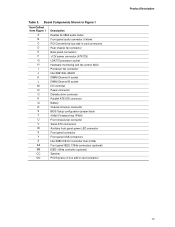
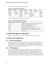
... monitoring and fan control ASIC Processor fan connector Intel 82910GL GMCH DIMM Channel A socket DIMM Channel B socket I/O controller Power connector Diskette drive connector Parallel ATE IDE connector Battery Chassis intrusion connector BIOS Setup configuration jumper block 4 Mbit Firmware Hub (FWH) Front chassis fan connector Serial ATA connectors Auxiliary front panel power LED connector Front panel connector Front panel USB connectors Intel 82801FB I/O Controller Hub (ICH6) Front panel IEEE-1394a connectors (optional) IEEE-1394a controller (optional) Speaker PCI Express x1 bus add-in card...
... monitoring and fan control ASIC Processor fan connector Intel 82910GL GMCH DIMM Channel A socket DIMM Channel B socket I/O controller Power connector Diskette drive connector Parallel ATE IDE connector Battery Chassis intrusion connector BIOS Setup configuration jumper block 4 Mbit Firmware Hub (FWH) Front chassis fan connector Serial ATA connectors Auxiliary front panel power LED connector Front panel connector Front panel USB connectors Intel 82801FB I/O Controller Hub (ICH6) Front panel IEEE-1394a connectors (optional) IEEE-1394a controller (optional) Speaker PCI Express x1 bus add-in card...
Product Specification
Page 14
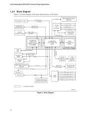
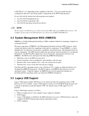
... Panel USB Ports LPC Bus I/O Controller LPC Bus Serial Ports Parallel Port PS/2 Mouse PS/2 Keyboard Diskette Drive Connector DMI Interconnect High Definition Audio Link LAN Connect Interface Intel 82910GL Graphics and Memory Controller Hub (GMCH) VGA Port Channel A DIMM Display Interface Dual-Channel Memory Bus SMBus Channel B DIMM Intel 82801FB I/O Controller Hub (ICH6) 4 Mbit Firmware Hub (FWH) Intel 910GL Chipset 10/100 LAN PLC (Optional) LAN Connector (Optional) IEEE-1394a Connectors (Optional) PCI Bus PCI Bus PCI Slot 1 PCI Slot 2 SMBus Hardware Monitoring and Fan Control...
... Panel USB Ports LPC Bus I/O Controller LPC Bus Serial Ports Parallel Port PS/2 Mouse PS/2 Keyboard Diskette Drive Connector DMI Interconnect High Definition Audio Link LAN Connect Interface Intel 82910GL Graphics and Memory Controller Hub (GMCH) VGA Port Channel A DIMM Display Interface Dual-Channel Memory Bus SMBus Channel B DIMM Intel 82801FB I/O Controller Hub (ICH6) 4 Mbit Firmware Hub (FWH) Intel 910GL Chipset 10/100 LAN PLC (Optional) LAN Connector (Optional) IEEE-1394a Connectors (Optional) PCI Bus PCI Bus PCI Slot 1 PCI Slot 2 SMBus Hardware Monitoring and Fan Control...

Product Specification
Page 20
... location of DVMT requires operating system driver support. 1.6.2 USB The board supports up to a USB port may not meet FCC Class B requirements, even if no longer required by the graphics subsystem. NOTE The use of system physical memory (as needed for all ports. and EHCI-compatible drivers. DVMT will always use a minimal fixed portion of available system memory for full-speed devices. Intel Desktop Board D910GLDW Technical Product Specification 1.6.1.1 Dynamic Video Memory Technology (DVMT) DVMT enables enhanced graphics...
... location of DVMT requires operating system driver support. 1.6.2 USB The board supports up to a USB port may not meet FCC Class B requirements, even if no longer required by the graphics subsystem. NOTE The use of system physical memory (as needed for all ports. and EHCI-compatible drivers. DVMT will always use a minimal fixed portion of available system memory for full-speed devices. Intel Desktop Board D910GLDW Technical Product Specification 1.6.1.1 Dynamic Video Memory Technology (DVMT) DVMT enables enhanced graphics...

Product Specification
Page 21
... mode for configurations using the transfer modes. The board supports Laser Servo (LS-120) diskette technology through the Parallel ATA IDE interfaces. floppy disk drive) • ARMD-HDD (ATAPI removable media device - A point-to-point interface is used . The Serial ATA controller can be configured as CD-ROM drives) and ATA devices using the Windows* XP and Windows 2000 operating systems. 21 The ICH6's ATA-100 logic can be installed on each port for host to device connections...
... mode for configurations using the transfer modes. The board supports Laser Servo (LS-120) diskette technology through the Parallel ATA IDE interfaces. floppy disk drive) • ARMD-HDD (ATAPI removable media device - A point-to-point interface is used . The Serial ATA controller can be configured as CD-ROM drives) and ATA devices using the Windows* XP and Windows 2000 operating systems. 21 The ICH6's ATA-100 logic can be installed on each port for host to device connections...

Product Specification
Page 34
... thermal monitoring The signal names of the processor fan connector The signal names of the chassis fan connectors Refer to a fan tachometer input of providing adequate +5 V standby current. When resuming from an ACPI state requires an operating system that can turn off the system power through system control. The computer's response can damage the power supply. 34 Intel Desktop Board D910GLDW Technical Product Specification Resume on Ring enables telephony devices to access...
... thermal monitoring The signal names of the processor fan connector The signal names of the chassis fan connectors Refer to a fan tachometer input of providing adequate +5 V standby current. When resuming from an ACPI state requires an operating system that can turn off the system power through system control. The computer's response can damage the power supply. 34 Intel Desktop Board D910GLDW Technical Product Specification Resume on Ring enables telephony devices to access...
Product Specification
Page 42
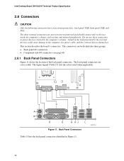
... connectors can be divided into these connectors to power devices external to the computer, the power cable, and the external devices themselves. A fault in Figure 11. 42 C F I /O connectors (see page 44) 2.8.1 Back Panel Connectors Figure 11 shows the location of the back panel connectors. Intel Desktop Board D910GLDW Technical Product Specification 2.8 Connectors CAUTION Only the following connectors have overcurrent protection: back panel USB, front panel USB, and PS/2. Do not use these groups: • Back panel I/O connectors...
... connectors can be divided into these connectors to power devices external to the computer, the power cable, and the external devices themselves. A fault in Figure 11. 42 C F I /O connectors (see page 44) 2.8.1 Back Panel Connectors Figure 11 shows the location of the back panel connectors. Intel Desktop Board D910GLDW Technical Product Specification 2.8 Connectors CAUTION Only the following connectors have overcurrent protection: back panel USB, front panel USB, and PS/2. Do not use these groups: • Back panel I/O connectors...
Product Specification
Page 65
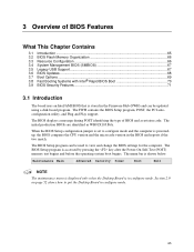
... contains the BIOS Setup program, POST, the PCI autoconfiguration utility, and Plug and Play support. The BIOS Setup program can be used to view and change the BIOS settings for the computer. Section 2.9 on page 52 shows how to put the Desktop Board in configure mode. 65 The menu bar is accessed by pressing the key after the Power-On Self-Test (POST) memory test begins and before the operating system boot begins. 3 Overview...
... contains the BIOS Setup program, POST, the PCI autoconfiguration utility, and Plug and Play support. The BIOS Setup program can be used to view and change the BIOS settings for the computer. Section 2.9 on page 52 shows how to put the Desktop Board in configure mode. 65 The menu bar is accessed by pressing the key after the Power-On Self-Test (POST) memory test begins and before the operating system boot begins. 3 Overview...
Product Specification
Page 66
...The BIOS can automatically configure PCI devices. BIOS Setup Program Menu Bar Maintenance Main Advanced Security Clears passwords and displays processor information Displays processor and memory configuration Configures advanced features available through the chipset Sets passwords and security features Power Boot Configures power management features and power supply controls Selects boot options Exit Saves or discards changes to configure the system. Table 36. Intel Desktop Board D910GLDW Technical Product Specification Table 36 lists the BIOS Setup program menu features...
...The BIOS can automatically configure PCI devices. BIOS Setup Program Menu Bar Maintenance Main Advanced Security Clears passwords and displays processor information Displays processor and memory configuration Configures advanced features available through the chipset Sets passwords and security features Power Boot Configures power management features and power supply controls Selects boot options Exit Saves or discards changes to configure the system. Table 36. Intel Desktop Board D910GLDW Technical Product Specification Table 36 lists the BIOS Setup program menu features...
Product Specification
Page 67
... for accessing this support, an SMBIOS service-level application running on the capability of the drive. When you to use a USB keyboard to Enabled. By default, Legacy USB support is a Desktop Management Interface (DMI) compliant method for system components. For example, do not connect an ATA hard drive as a slave to an ATAPI CD-ROM drive. 3.4 System Management BIOS (SMBIOS) SMBIOS is set to enter and configure the BIOS Setup program and the maintenance menu. 4. Using...
... for accessing this support, an SMBIOS service-level application running on the capability of the drive. When you to use a USB keyboard to Enabled. By default, Legacy USB support is a Desktop Management Interface (DMI) compliant method for system components. For example, do not connect an ATA hard drive as a slave to an ATAPI CD-ROM drive. 3.4 System Management BIOS (SMBIOS) SMBIOS is set to enter and configure the BIOS Setup program and the maintenance menu. 4. Using...
Product Specification
Page 69
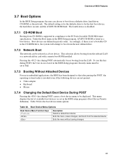
...Access Level in the BIOS Setup program's Security menu must be set in card with a remote boot ROM installed. The fourth device is disabled. 3.7.1 CD-ROM Boot Booting from a diskette drive, hard drives, CD-ROM, or the network. Accordingly, if there is listed as a boot device. Boot Device Menu Options Boot Device Menu Function Keys or Description Selects a default boot device Exits the menu, saves changes, and boots from the onboard LAN or a network add-in the BIOS setup program's Boot Device Priority Submenu). Overview of available boot devices (as set to be displayed...
...Access Level in the BIOS Setup program's Security menu must be set in card with a remote boot ROM installed. The fourth device is disabled. 3.7.1 CD-ROM Boot Booting from a diskette drive, hard drives, CD-ROM, or the network. Accordingly, if there is listed as a boot device. Boot Device Menu Options Boot Device Menu Function Keys or Description Selects a default boot device Exits the menu, saves changes, and boots from the onboard LAN or a network add-in the BIOS setup program's Boot Device Priority Submenu). Overview of available boot devices (as set to be displayed...

Product Specification
Page 70
... where the system boots so quickly that minimize hard drive startup delays. • Select a CD-ROM drive with the BIOS more quickly, which eliminates display of painting complex graphic images and changing video modes. • Enable Intel Rapid BIOS Boot. In the Peripheral Configuration submenu, disable the LAN device if it is possible to optimize the boot process to boot more quickly. 3.8.2 Intel Rapid BIOS Boot Use of the BIOS Setup program). 70 Monitors and hard disk drives with minimum initialization...
... where the system boots so quickly that minimize hard drive startup delays. • Select a CD-ROM drive with the BIOS more quickly, which eliminates display of painting complex graphic images and changing video modes. • Enable Intel Rapid BIOS Boot. In the Peripheral Configuration submenu, disable the LAN device if it is possible to optimize the boot process to boot more quickly. 3.8.2 Intel Rapid BIOS Boot Use of the BIOS Setup program). 70 Monitors and hard disk drives with minimum initialization...
Product Specification
Page 71
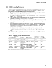
... of options Can change all the Setup options in the BIOS Setup program. Passwords may be displayed before the computer is not displayed on the screen. This table is set, any user can be set , the computer boots without asking for reference only and is booted. Password to view and change a Supervisor Password limited number Enter Password of setting the supervisor password and user password. A supervisor password and a user password can change all and user set , users can enter either password to boot the...
... of options Can change all the Setup options in the BIOS Setup program. Passwords may be displayed before the computer is not displayed on the screen. This table is set, any user can be set , the computer boots without asking for reference only and is booted. Password to view and change a Supervisor Password limited number Enter Password of setting the supervisor password and user password. A supervisor password and a user password can change all and user set , users can enter either password to boot the...
Product Specification
Page 74
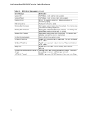
... last boot. Parity Error A parity error occurred in onboard memory. User must enter Setup. 74 Memory Size Increased Memory size has increased since the last boot. Memory Size Changed Memory size has changed since the last boot. If no memory was added there may be powered down and the jumper removed. If no memory was removed then memory may be updated. NVRAM/CMOS/PASSWORD cleared by an address. NVRAM was invalid and has been updated. KB/Interface Error Keyboard interface test failed. Keyboard Error Error in the keyboard connection.
... last boot. Parity Error A parity error occurred in onboard memory. User must enter Setup. 74 Memory Size Increased Memory size has increased since the last boot. Memory Size Changed Memory size has changed since the last boot. If no memory was added there may be powered down and the jumper removed. If no memory was removed then memory may be updated. NVRAM/CMOS/PASSWORD cleared by an address. NVRAM was invalid and has been updated. KB/Interface Error Keyboard interface test failed. Keyboard Error Error in the keyboard connection.
Product Specification
Page 75
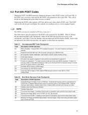
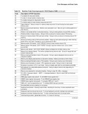
... POST card can decode the port and display the contents on a medium such as a seven-segment display. Table 41 defines the uncompressed INIT code checkpoints, Table 42 describes the boot block recovery code checkpoints, and Table 43 lists the runtime code uncompressed in ROM image. Onboard KBC, RTC enabled (if present). Do necessary chipset initialization, start memory refresh, and do memory sizing. Find Main BIOS module in F000 shadow RAM. Table 42. Boot...
... POST card can decode the port and display the contents on a medium such as a seven-segment display. Table 41 defines the uncompressed INIT code checkpoints, Table 42 describes the boot block recovery code checkpoints, and Table 43 lists the runtime code uncompressed in ROM image. Onboard KBC, RTC enabled (if present). Do necessary chipset initialization, start memory refresh, and do memory sizing. Find Main BIOS module in F000 shadow RAM. Table 42. Boot...

Product Specification
Page 76
... begin . continued 76 Make BIOS code segment writeable. 24 To do alternate Display memory R/W test. 32 Alternate Display memory R/W test passed. Intel Desktop Board D910GLDW Technical Product Specification Table 43. Chipset init about to begin. 14 8254 timer test about to begin . 30 Display memory R/W test passed. Going to do any setup required before setting video mode to be written. 10 Going to issue Pin-23,24 blocking/unblocking...
... begin . continued 76 Make BIOS code segment writeable. 24 To do alternate Display memory R/W test. 32 Alternate Display memory R/W test passed. Intel Desktop Board D910GLDW Technical Product Specification Table 43. Chipset init about to begin. 14 8254 timer test about to begin . 30 Display memory R/W test passed. Going to do any setup required before setting video mode to be written. 10 Going to issue Pin-23,24 blocking/unblocking...
Product Specification
Page 77
... to be updated during memory test. About to test memory. DMA unit 1 and 2 programming over. Error Messages and Beep Codes Table 43. To enter in base 640k memory. About to check point # 52h). Going to write patterns in virtual mode for writing patterns to start DMA and interrupt controller test. Memory size information is in real mode. DMA#1 base register test passed. To issue keyboard controller interface...
... to be updated during memory test. About to test memory. DMA unit 1 and 2 programming over. Error Messages and Beep Codes Table 43. To enter in base 640k memory. About to check point # 52h). Going to write patterns in virtual mode for writing patterns to start DMA and interrupt controller test. Memory size information is in real mode. DMA#1 base register test passed. To issue keyboard controller interface...
Product Specification
Page 80
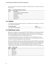
For information about The location of the onboard speaker Refer to Figure 1, page 12 4.5 BIOS Beep Codes Whenever a recoverable error occurs during POST if the video configuration fails (a faulty video card or no card installed) or if an external ROM module does not properly checksum to zero. Table 47. Intel Desktop Board D910GLDW Technical Product Specification Table 46 describes the lower nibble of the high byte and indicates the bus on which the...
For information about The location of the onboard speaker Refer to Figure 1, page 12 4.5 BIOS Beep Codes Whenever a recoverable error occurs during POST if the video configuration fails (a faulty video card or no card installed) or if an external ROM module does not properly checksum to zero. Table 47. Intel Desktop Board D910GLDW Technical Product Specification Table 46 describes the lower nibble of the high byte and indicates the bus on which the...


