

Product Specification
Page 2
... absence or characteristics of any license, express or implied, by estoppel or otherwise, to only standard Intel® Desktop Board D910GLDW with BIOS identifier WB91X10J.86A. All rights reserved. September 2004 Second release of the Intel® Desktop Board D910GLDW Technical Product Specification. NO LICENSE, EXPRESS OR IMPLIED, BY ESTOPPEL OR OTHERWISE, TO ANY INTELLECTUAL...
... absence or characteristics of any license, express or implied, by estoppel or otherwise, to only standard Intel® Desktop Board D910GLDW with BIOS identifier WB91X10J.86A. All rights reserved. September 2004 Second release of the Intel® Desktop Board D910GLDW Technical Product Specification. NO LICENSE, EXPRESS OR IMPLIED, BY ESTOPPEL OR OTHERWISE, TO ANY INTELLECTUAL...
Product Specification
Page 3
...components, connectors, power and environmental requirements, and the BIOS for general audiences. Intended Audience The TPS is specifically not intended for the Intel® Desktop Board D910GLDW. CAUTION Cautions are used on the Desktop Board D910GLDW A map of the resources of the Desktop Board... The features supported by the BIOS Setup program A description of the hardware used ...
...components, connectors, power and environmental requirements, and the BIOS for general audiences. Intended Audience The TPS is specifically not intended for the Intel® Desktop Board D910GLDW. CAUTION Cautions are used on the Desktop Board D910GLDW A map of the resources of the Desktop Board... The features supported by the BIOS Setup program A description of the hardware used ...

Product Specification
Page 6
Intel Desktop Board D910GLDW Technical Product Specification 2.5 PCI Configuration Space Map 39 2.6 Interrupts ...40 2.7 PCI Conventional Interrupt Routing Map 41 2.8 Connectors...42 2.8.1 Back Panel Connectors 42 2.8.2 Component-side Connectors ... ...69 3.7.1 CD-ROM Boot 69 3.7.2 Network Boot 69 3.7.3 Booting Without Attached Devices 69 3.7.4 Changing the Default Boot Device During POST 69 3.8 Fast Booting Systems with Intel® Rapid BIOS Boot 70 3.8.1 Peripheral Selection and Configuration 70 3.8.2 Intel Rapid BIOS Boot 70 3.9 BIOS Security Features 71 vi
Intel Desktop Board D910GLDW Technical Product Specification 2.5 PCI Configuration Space Map 39 2.6 Interrupts ...40 2.7 PCI Conventional Interrupt Routing Map 41 2.8 Connectors...42 2.8.1 Back Panel Connectors 42 2.8.2 Component-side Connectors ... ...69 3.7.1 CD-ROM Boot 69 3.7.2 Network Boot 69 3.7.3 Booting Without Attached Devices 69 3.7.4 Changing the Default Boot Device During POST 69 3.8 Fast Booting Systems with Intel® Rapid BIOS Boot 70 3.8.1 Peripheral Selection and Configuration 70 3.8.2 Intel Rapid BIOS Boot 70 3.9 BIOS Security Features 71 vi
Product Specification
Page 7
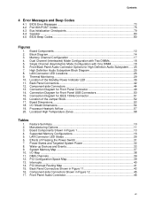
... in Figure 12 45 17. Power States and Targeted System Power 32 8. Contents 4 Error Messages and Beep Codes 4.1 BIOS Error Messages 73 4.2 Port 80h POST Codes 75 4.3 Bus Initialization Checkpoints 79 4.4 Speaker ...80 4.5 BIOS Beep Codes...80 Figures 1. Connection Diagram for IEEE 1394a Connector 51 16. Location of the Standby Power Indicator...
... in Figure 12 45 17. Power States and Targeted System Power 32 8. Contents 4 Error Messages and Beep Codes 4.1 BIOS Error Messages 73 4.2 Port 80h POST Codes 75 4.3 Bus Initialization Checkpoints 79 4.4 Speaker ...80 4.5 BIOS Beep Codes...80 Figures 1. Connection Diagram for IEEE 1394a Connector 51 16. Location of the Standby Power Indicator...

Product Specification
Page 8
... Fan Connectors 46 19. Main Power Connector 47 23. BIOS Setup Configuration Jumper Settings 52 29. Environmental Specifications 60 33. Uncompressed INIT Code Checkpoints 75 42. Bus Initialization Checkpoints 79 45. Intel Desktop Board D910GLDW Technical Product Specification 18. DC Loading Characteristics 55 30. ... for a Two-Color Power LED 49 28. Fan Connector Current Capability 55 31. Safety Regulations ...61 34. BIOS Setup Program Menu Bar 66 37. BIOS Setup Program Function Keys 66 38. Boot Device Menu Options 69 39. Supervisor and User Password Functions 71 40...
... Fan Connectors 46 19. Main Power Connector 47 23. BIOS Setup Configuration Jumper Settings 52 29. Environmental Specifications 60 33. Uncompressed INIT Code Checkpoints 75 42. Bus Initialization Checkpoints 79 45. Intel Desktop Board D910GLDW Technical Product Specification 18. DC Loading Characteristics 55 30. ... for a Two-Color Power LED 49 28. Fan Connector Current Capability 55 31. Safety Regulations ...61 34. BIOS Setup Program Menu Bar 66 37. BIOS Setup Program Function Keys 66 38. Boot Device Menu Options 69 39. Supervisor and User Password Functions 71 40...
Product Specification
Page 10
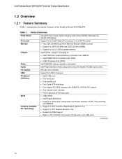
...Intel Desktop Board D910GLDW Technical Product Specification 1.2 Overview 1.2.1 Feature Summary Table 1 summarizes the major features of : • Intel® 82910GL Graphics Memory Controller Hub (GMCH) • Intel® 82801FB I/O Controller Hub (ICH6) • 4 Mbit Firmware Hub (FWH) Intel® GMA900 onboard graphics subsystem Intel...support • One diskette drive interface • PS/2* keyboard and mouse ports • 4 Mbit FWH • Intel® Rapid BIOS Boot • Support for Advanced Configuration and Power Interface (ACPI), Plug and Play, and SMBIOS • Support ...
...Intel Desktop Board D910GLDW Technical Product Specification 1.2 Overview 1.2.1 Feature Summary Table 1 summarizes the major features of : • Intel® 82910GL Graphics Memory Controller Hub (GMCH) • Intel® 82801FB I/O Controller Hub (ICH6) • 4 Mbit Firmware Hub (FWH) Intel® GMA900 onboard graphics subsystem Intel...support • One diskette drive interface • PS/2* keyboard and mouse ports • 4 Mbit FWH • Intel® Rapid BIOS Boot • Support for Advanced Configuration and Power Interface (ACPI), Plug and Play, and SMBIOS • Support ...
Product Specification
Page 13
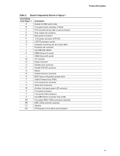
... connectors +12V power connector (ATX12V) LGA775 processor socket Hardware monitoring and fan control ASIC Processor fan connector Intel 82910GL GMCH DIMM Channel A socket DIMM Channel B socket I/O controller Power connector Diskette drive connector Parallel ATE IDE connector Battery... Chassis intrusion connector BIOS Setup configuration jumper block 4 Mbit Firmware Hub (FWH) Front chassis fan connector Serial ATA connectors Auxiliary front panel power LED connector Front panel connector Front panel USB connectors Intel 82801FB I/O Controller Hub (ICH6) Front ...
... connectors +12V power connector (ATX12V) LGA775 processor socket Hardware monitoring and fan control ASIC Processor fan connector Intel 82910GL GMCH DIMM Channel A socket DIMM Channel B socket I/O controller Power connector Diskette drive connector Parallel ATE IDE connector Battery... Chassis intrusion connector BIOS Setup configuration jumper block 4 Mbit Firmware Hub (FWH) Front chassis fan connector Serial ATA connectors Auxiliary front panel power LED connector Front panel connector Front panel USB connectors Intel 82801FB I/O Controller Hub (ICH6) Front ...
Product Specification
Page 16
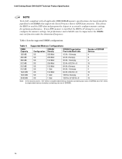
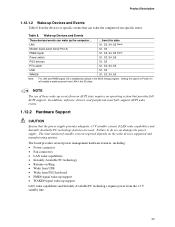
If non-SPD memory is installed, the BIOS will attempt to single-sided memory modules (containing one row of SDRAM) and "SS" refers to correctly configure the memory settings, but performance and reliability ... M x 8 16 Note: In the second column, "DS" refers to double-sided memory modules (containing two rows of SDRAM). 16 Table 4 lists the supported DIMM configurations. Intel Desktop Board D910GLDW Technical Product Specification NOTE To be fully compliant with DIMMs that support the Serial Presence Detect (SPD) data structure. This allows the...
If non-SPD memory is installed, the BIOS will attempt to single-sided memory modules (containing one row of SDRAM) and "SS" refers to correctly configure the memory settings, but performance and reliability ... M x 8 16 Note: In the second column, "DS" refers to double-sided memory modules (containing two rows of SDRAM). 16 Table 4 lists the supported DIMM configurations. Intel Desktop Board D910GLDW Technical Product Specification NOTE To be fully compliant with DIMMs that support the Serial Presence Detect (SPD) data structure. This allows the...
Product Specification
Page 19
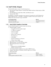
Product Description 1.6 Intel® 910GL Chipset The Intel 910GL chipset consists of the BIOS. The FWH provides the nonvolatile storage of the following : • Integrated graphics controller ⎯ 32 bpp (Bits Per Pixel) graphics engine ⎯ ... compliant interface • Video hardware motion compensation for software MPEG2 decode • Dynamic Video Memory Technology (DVMT) support up to 224 MB • Intel® Zoom Utility For information about DVMT Obtaining graphics software and utilities Refer to Section 0, page 20 Section 1.3, page 15 19 For information about The...
Product Description 1.6 Intel® 910GL Chipset The Intel 910GL chipset consists of the BIOS. The FWH provides the nonvolatile storage of the following : • Integrated graphics controller ⎯ 32 bpp (Bits Per Pixel) graphics engine ⎯ ... compliant interface • Video hardware motion compensation for software MPEG2 decode • Dynamic Video Memory Technology (DVMT) support up to 224 MB • Intel® Zoom Utility For information about DVMT Obtaining graphics software and utilities Refer to Section 0, page 20 Section 1.3, page 15 19 For information about The...

Product Specification
Page 20
... supports up to the operating system when the additional system memory is no device is as set in the BIOS Setup program) for performing graphics functions. and EHCI-compatible drivers. Intel Desktop Board D910GLDW Technical Product Specification 1.6.1.1 Dynamic Video Memory Technology (DVMT) DVMT enables enhanced graphics and memory performance through Direct AGP, and...
... supports up to the operating system when the additional system memory is no device is as set in the BIOS Setup program) for performing graphics functions. and EHCI-compatible drivers. Intel Desktop Board D910GLDW Technical Product Specification 1.6.1.1 Dynamic Video Memory Technology (DVMT) DVMT enables enhanced graphics and memory performance through Direct AGP, and...

Product Specification
Page 21
The BIOS supports Logical Block Addressing (LBA) and Extended Cylinder Head Sector (ECHS) translation modes. The drive reports the transfer rate and translation...operate in both legacy and native modes. The Parallel ATA IDE interface also supports ATAPI devices (such as a boot device by setting the BIOS Setup program's Boot menu to one bus-mastering Parallel ATA IDE interface. For compatibility, the underlying Serial ATA functionality is used for a maximum.... • ATA-100: DMA protocol on IDE bus supporting host and target throttling and transfer rates of up to the BIOS.
The BIOS supports Logical Block Addressing (LBA) and Extended Cylinder Head Sector (ECHS) translation modes. The drive reports the transfer rate and translation...operate in both legacy and native modes. The Parallel ATA IDE interface also supports ATAPI devices (such as a boot device by setting the BIOS Setup program's Boot menu to one bus-mastering Parallel ATA IDE interface. For compatibility, the underlying Serial ATA functionality is used for a maximum.... • ATA-100: DMA protocol on IDE bus supporting host and target throttling and transfer rates of up to the BIOS.
Product Specification
Page 23
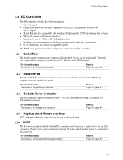
...the back panel. The serial port supports data transfers at speeds up event interface • PCI Conventional bus power management support The BIOS Setup program provides configuration options for one 1.44 MB or 2.88 MB diskette drive • Intelligent power management, including a programmable ...Refer to Figure 12, page 44 1.8.4 Keyboard and Mouse Interface PS/2 keyboard and mouse connectors are located on the back panel. Use the BIOS Setup program to Figure 11, page 42 23 Product Description 1.8 I/O Controller The I/O controller provides the following features: • One serial ...
...the back panel. The serial port supports data transfers at speeds up event interface • PCI Conventional bus power management support The BIOS Setup program provides configuration options for one 1.44 MB or 2.88 MB diskette drive • Intelligent power management, including a programmable ...Refer to Figure 12, page 44 1.8.4 Keyboard and Mouse Interface PS/2 keyboard and mouse connectors are located on the back panel. Use the BIOS Setup program to Figure 11, page 42 23 Product Description 1.8 I/O Controller The I/O controller provides the following features: • One serial ...
Product Specification
Page 27
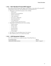
For information about Obtaining LAN software and drivers Refer to boot from Intel's World Wide Web site. Product Description 1.10.2 Alert Standard Format (ASF) Support The boards provide the following ASF support for ... cards and PCI Conventional bus add-in LAN cards installed in PCI Conventional bus slot 2: • Monitoring of system firmware progress events, including: ⎯ BIOS present ⎯ Primary processor initialization ⎯ Memory initialization ⎯ Video initialization ⎯ PCI resource configuration ⎯ Hard-disk initialization ⎯ User authentication ...
For information about Obtaining LAN software and drivers Refer to boot from Intel's World Wide Web site. Product Description 1.10.2 Alert Standard Format (ASF) Support The boards provide the following ASF support for ... cards and PCI Conventional bus add-in LAN cards installed in PCI Conventional bus slot 2: • Monitoring of system firmware progress events, including: ⎯ BIOS present ⎯ Primary processor initialization ⎯ Memory initialization ⎯ Video initialization ⎯ PCI resource configuration ⎯ Hard-disk initialization ⎯ User authentication ...

Product Specification
Page 30
...that detects if the chassis cover is recommended that processor fan speed control remain enabled (default BIOS setting) when using Intel® Desktop Utilities, LANDesk* software, or thirdparty software. The overall system noise reduction ...BIOS. Disabling the chassis fan speed control results in the fan operating at the minimum necessary speeds. The chassis fan speed control feature should be disabled if a self-controlled chassis fan is implemented at full speed. The level of the fan connectors Refer to any controlled chassis fan header. Intel Desktop Board D910GLDW...
...that detects if the chassis cover is recommended that processor fan speed control remain enabled (default BIOS setting) when using Intel® Desktop Utilities, LANDesk* software, or thirdparty software. The overall system noise reduction ...BIOS. Disabling the chassis fan speed control results in the fan operating at the minimum necessary speeds. The chassis fan speed control feature should be disabled if a self-controlled chassis fan is implemented at full speed. The level of the fan connectors Refer to any controlled chassis fan header. Intel Desktop Board D910GLDW...
Product Specification
Page 33
...; PME# signal wake-up support • WAKE# signal wake-up support LAN wake capabilities and Instantly Available PC technology require power from LAN in the BIOS Setup program. The board provides several power management hardware features, including: • Power connector • Fan connectors • LAN wake capabilities • Instantly Available PC...
...; PME# signal wake-up support • WAKE# signal wake-up support LAN wake capabilities and Instantly Available PC technology require power from LAN in the BIOS Setup program. The board provides several power management hardware features, including: • Power connector • Fan connectors • LAN wake capabilities • Instantly Available PC...

Product Specification
Page 34
...resuming from an ACPI state requires an operating system that can damage the power supply. 34 The computer's response can turn off or in the BIOS Setup program's Boot menu. For information about The location of the main power connector The signal names of the main power connector Refer to ...the board is in the S0 or S1 state. • The fans are off when the board is off the system power through system control. Intel Desktop Board D910GLDW Technical Product Specification Resume on Ring enables telephony devices to access the computer when it was in a power-managed state.
...resuming from an ACPI state requires an operating system that can damage the power supply. 34 The computer's response can turn off or in the BIOS Setup program's Boot menu. For information about The location of the main power connector The signal names of the main power connector Refer to ...the board is in the S0 or S1 state. • The fans are off when the board is off the system power through system control. Intel Desktop Board D910GLDW Technical Product Specification Resume on Ring enables telephony devices to access the computer when it was in a power-managed state.
Product Specification
Page 36
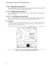
Figure 10 shows the location of the Standby Power Indicator LED 36 CR3J1 OM17313 Figure 10. Location of the standby power indicator LED. Intel Desktop Board D910GLDW Technical Product Specification 1.12.2.8 PME# Signal Wake-up Support When the PME# signal on the PCI Conventional bus is asserted, the computer... wakes from an ACPI S1, S3, S4, or S5 state (with Wake on PME enabled in BIOS). 1.12.2.9 WAKE# Signal Wake-up Support When ...
Figure 10 shows the location of the Standby Power Indicator LED 36 CR3J1 OM17313 Figure 10. Location of the standby power indicator LED. Intel Desktop Board D910GLDW Technical Product Specification 1.12.2.8 PME# Signal Wake-up Support When the PME# signal on the PCI Conventional bus is asserted, the computer... wakes from an ACPI S1, S3, S4, or S5 state (with Wake on PME enabled in BIOS). 1.12.2.9 WAKE# Signal Wake-up Support When ...
Product Specification
Page 37
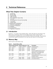
EFFFF 64 KB 800 K - 896 K C8000 - Dependent on video adapter used. Video memory and BIOS Extended BIOS data (movable by text found with their respective section headings. 2.2 Memory Map Table 9 lists the system memory map. System Memory Map Address...639 K - 640 K 512 K - 639 K 0 K - 512 K A0000 - C7FFF 9FC00 - 9FFFF 80000 - 9FBFF 00000 - 7FFFF 160 KB 1 KB 127 KB 512 KB Description Extended memory Runtime BIOS Reserved Potential available high DOS memory (open to the PCI Conventional bus). Table 9 describes the system memory map, Table 10 shows the I /O Map...38 2.4 DMA...
EFFFF 64 KB 800 K - 896 K C8000 - Dependent on video adapter used. Video memory and BIOS Extended BIOS data (movable by text found with their respective section headings. 2.2 Memory Map Table 9 lists the system memory map. System Memory Map Address...639 K - 640 K 512 K - 639 K 0 K - 512 K A0000 - C7FFF 9FC00 - 9FFFF 80000 - 9FBFF 00000 - 7FFFF 160 KB 1 KB 127 KB 512 KB Description Extended memory Runtime BIOS Reserved Potential available high DOS memory (open to the PCI Conventional bus). Table 9 describes the system memory map, Table 10 shows the I /O Map...38 2.4 DMA...
Product Specification
Page 52
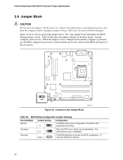
... reports if the two match. 1 3 J8J4 OM17316 Figure 16. Otherwise, the board could be damaged. BIOS Setup Configuration Jumper Settings Function/Mode Normal Jumper Setting 1-2 1 3 Configuration The BIOS uses current configuration information and passwords for the three modes: normal, configure, and recovery. Configure 2-3 1 After the POST ...28. Always turn off the power and unplug the power cord from the computer before changing a jumper setting. Intel Desktop Board D910GLDW Technical Product Specification 2.9 Jumper Block CAUTION Do not move the jumper with the power on.
... reports if the two match. 1 3 J8J4 OM17316 Figure 16. Otherwise, the board could be damaged. BIOS Setup Configuration Jumper Settings Function/Mode Normal Jumper Setting 1-2 1 3 Configuration The BIOS uses current configuration information and passwords for the three modes: normal, configure, and recovery. Configure 2-3 1 After the POST ...28. Always turn off the power and unplug the power cord from the computer before changing a jumper setting. Intel Desktop Board D910GLDW Technical Product Specification 2.9 Jumper Block CAUTION Do not move the jumper with the power on.
Product Specification
Page 65
... What This Chapter Contains 3.1 Introduction ...65 3.2 BIOS Flash Memory Organization 66 3.3 Resource Configuration 66 3.4 System Management BIOS (SMBIOS 67 3.5 Legacy USB Support...67 3.6 BIOS Updates ...68 3.7 Boot Options ...69 3.8 Fast Booting Systems with Intel® Rapid BIOS Boot 70 3.9 BIOS Security Features 71 3.1 Introduction The board uses an Intel/AMI BIOS that is stored in the Firmware Hub...
... What This Chapter Contains 3.1 Introduction ...65 3.2 BIOS Flash Memory Organization 66 3.3 Resource Configuration 66 3.4 System Management BIOS (SMBIOS 67 3.5 Legacy USB Support...67 3.6 BIOS Updates ...68 3.7 Boot Options ...69 3.8 Fast Booting Systems with Intel® Rapid BIOS Boot 70 3.9 BIOS Security Features 71 3.1 Introduction The board uses an Intel/AMI BIOS that is stored in the Firmware Hub...


