
User Manual
Page 3
.... CAUTION Cautions warn the user about board layout, component installation, BIOS update, and regulatory requirements for technically qualified personnel. It is intended for Intel® Desktop Board D915GEV/D915GUX/D915GAV/D915GAG. iii NOTE Notes call attention to update the BIOS 4 Trusted Platform Module (Optional): information about setting... arranged as follows: 1 Desktop Board Features: a summary of data. Information Layout The chapters in this Product Guide are used in this manual: WARNING Warnings indicate conditions that, if not observed, can cause personal injury.
.... CAUTION Cautions warn the user about board layout, component installation, BIOS update, and regulatory requirements for technically qualified personnel. It is intended for Intel® Desktop Board D915GEV/D915GUX/D915GAV/D915GAG. iii NOTE Notes call attention to update the BIOS 4 Trusted Platform Module (Optional): information about setting... arranged as follows: 1 Desktop Board Features: a summary of data. Information Layout The chapters in this Product Guide are used in this manual: WARNING Warnings indicate conditions that, if not observed, can cause personal injury.

User Manual
Page 22
...and the video BIOS. Expandability The desktop boards support the following the instructions on page 59 in Chapter 3. You can be updated by specifying manual configuration in the Firmware Hub. You do not need to two IDE devices (such as hard drives) • ATAPI-style devices (such as... run the BIOS Setup program after installing a Serial ATA or IDE device. The BIOS is stored in the BIOS Setup program. 22 Intel Desktop Board D915GEV/D915GUX/D915GAV/D915GAG Product Guide Enhanced IDE Interface The ICH6's IDE interface handles the exchange of information between the processor and...
...and the video BIOS. Expandability The desktop boards support the following the instructions on page 59 in Chapter 3. You can be updated by specifying manual configuration in the Firmware Hub. You do not need to two IDE devices (such as hard drives) • ATAPI-style devices (such as... run the BIOS Setup program after installing a Serial ATA or IDE device. The BIOS is stored in the BIOS Setup program. 22 Intel Desktop Board D915GEV/D915GUX/D915GAV/D915GAG Product Guide Enhanced IDE Interface The ICH6's IDE interface handles the exchange of information between the processor and...
User Manual
Page 31
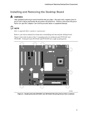
Failure to your chassis manual for instructions on installing and removing the desktop board. Figure 6 shows the location of the 11 mounting holes for regulatory requirements. Desktop Boards D915GEV and ...
Failure to your chassis manual for instructions on installing and removing the desktop board. Figure 6 shows the location of the 11 mounting holes for regulatory requirements. Desktop Boards D915GEV and ...

User Manual
Page 34
... down without tilting or sliding the processor in Figure 11. Make sure fingers align to the boxed processor manual or the Intel World Wide Web site at: http://support.intel.com/support/processors/pentium4/intnotes478.htm 34 II Install Processor 7. Close the Load Plate Installing the Processor Fan...how to attach the processor fan heat sink to the integrated processor fan heat sink RM, refer to the socket cutouts (see (Figure 11, H). Intel Desktop Board D915GEV/D915GUX/D915GAV/D915GAG Product Guide 6. J I ) close and engage the socket lever (Figure 12, J). Hold the processor with ...
... down without tilting or sliding the processor in Figure 11. Make sure fingers align to the boxed processor manual or the Intel World Wide Web site at: http://support.intel.com/support/processors/pentium4/intnotes478.htm 34 II Install Processor 7. Close the Load Plate Installing the Processor Fan...how to attach the processor fan heat sink to the integrated processor fan heat sink RM, refer to the socket cutouts (see (Figure 11, H). Intel Desktop Board D915GEV/D915GUX/D915GAV/D915GAG Product Guide 6. J I ) close and engage the socket lever (Figure 12, J). Hold the processor with ...

User Manual
Page 35
Connecting the Processor Fan Heat Sink Cable to the Processor Fan Connector Removing the Processor For instruction on how to remove the processor fan heat sink and processor, refer to the 4-pin processor fan connector (see Figure 13). Installing and Replacing Desktop Board Components Connecting the Processor Fan Heat Sink Cable Connect the processor fan heat sink cable to the processor installation manual or the Intel World Wide Web site at: http://support.intel.com/support/processors/pentium4/intnotes478.htm 35 OM16894 Figure 13.
Connecting the Processor Fan Heat Sink Cable to the Processor Fan Connector Removing the Processor For instruction on how to remove the processor fan heat sink and processor, refer to the 4-pin processor fan connector (see Figure 13). Installing and Replacing Desktop Board Components Connecting the Processor Fan Heat Sink Cable Connect the processor fan heat sink cable to the processor installation manual or the Intel World Wide Web site at: http://support.intel.com/support/processors/pentium4/intnotes478.htm 35 OM16894 Figure 13.
User Manual
Page 67
... User Initialization Wizard, a copy of the platform. 9. Create and document the password to compromise the security of the Emergency Recovery Archive (SPEmRecArchive.xml) should be manually backed up all new and updated keys associated with the Infineon Security Platform Software (Owner, Emergency Recovery Token, and User passwords) and Wave Systems EMBASSY...
... User Initialization Wizard, a copy of the platform. 9. Create and document the password to compromise the security of the Emergency Recovery Archive (SPEmRecArchive.xml) should be manually backed up all new and updated keys associated with the Infineon Security Platform Software (Owner, Emergency Recovery Token, and User passwords) and Wave Systems EMBASSY...
User Manual
Page 79
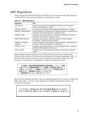
... according to comply with the EMC regulations stated in Table 19 when correctly installed in a compatible host system. If this is certified to the instruction manual. Limits and Methods of Measurement. (International) Voluntary Control for Electromagnetic Compatibility. (Australia and New Zealand) Limits and methods of measurement of Radio Disturbance Characteristics of...
... according to comply with the EMC regulations stated in Table 19 when correctly installed in a compatible host system. If this is certified to the instruction manual. Limits and Methods of Measurement. (International) Voluntary Control for Electromagnetic Compatibility. (Australia and New Zealand) Limits and methods of measurement of Radio Disturbance Characteristics of...


