Product Guide
Page 5
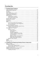
Contents 1 Desktop Board Features Supported Operating Systems 10 Desktop Board Components 11 Processor ...13 Main Memory...13 Intel® 945GC Express Chipset 14 Onboard Audio Subsystem 14 Input/Output (I/O) Controller 15 LAN Subsystem 15 LAN Subsystem Software...Battery ...22 Real-Time Clock 22 2 Installing and Replacing Desktop Board Components Before You Begin 23 Installation Precautions 24 Prevent Power Supply Overload 24 Observe Safety and Regulatory Requirements 24 Installing the I/O Shield 25 Installing and Removing the Desktop Board 26 Installing and Removing a Processor 27...
Contents 1 Desktop Board Features Supported Operating Systems 10 Desktop Board Components 11 Processor ...13 Main Memory...13 Intel® 945GC Express Chipset 14 Onboard Audio Subsystem 14 Input/Output (I/O) Controller 15 LAN Subsystem 15 LAN Subsystem Software...Battery ...22 Real-Time Clock 22 2 Installing and Replacing Desktop Board Components Before You Begin 23 Installation Precautions 24 Prevent Power Supply Overload 24 Observe Safety and Regulatory Requirements 24 Installing the I/O Shield 25 Installing and Removing the Desktop Board 26 Installing and Removing a Processor 27...

Product Guide
Page 6
Intel Desktop Board D945GCNL Product Guide Installing the Processor Fan Heat Sink 30 Connecting the Processor Fan Heat Sink Cable 31 Removing the Processor 31 Installing and Removing Memory 32 Installing DIMMs 34 Removing DIMMs 35 Installing and Removing a PCI Express x16 Card 36 Installing a PCI Express x16 Card 36... the IDE Cable 38 Connecting the Serial ATA (SATA) Cable 39 Connecting to Internal Headers 40 Installing a Front Panel Audio Solution for Intel® High Definition Audio 41 Connecting to the USB 2.0 Headers 42 Connecting to the Front Panel Header 42 Connecting to ...
Intel Desktop Board D945GCNL Product Guide Installing the Processor Fan Heat Sink 30 Connecting the Processor Fan Heat Sink Cable 31 Removing the Processor 31 Installing and Removing Memory 32 Installing DIMMs 34 Removing DIMMs 35 Installing and Removing a PCI Express x16 Card 36 Installing a PCI Express x16 Card 36... the IDE Cable 38 Connecting the Serial ATA (SATA) Cable 39 Connecting to Internal Headers 40 Installing a Front Panel Audio Solution for Intel® High Definition Audio 41 Connecting to the USB 2.0 Headers 42 Connecting to the Front Panel Header 42 Connecting to ...
Product Guide
Page 7
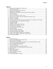
... Codes 57 11. Lift the Load Plate 28 8. Installing a DIMM 34 16. Location of Chassis Fan Headers 44 23. Remove the Processor from the Protective Processor Cover 29 10. Removing a PCI Express x16 Card 37 18. Desktop Board D945GCNL Components 12 3. Jumper Settings for Intel High Definition Audio 41 5. Safety Standards 59 13. Location of the...
... Codes 57 11. Lift the Load Plate 28 8. Installing a DIMM 34 16. Location of Chassis Fan Headers 44 23. Remove the Processor from the Protective Processor Cover 29 10. Removing a PCI Express x16 Card 37 18. Desktop Board D945GCNL Components 12 3. Jumper Settings for Intel High Definition Audio 41 5. Safety Standards 59 13. Location of the...
Product Guide
Page 14
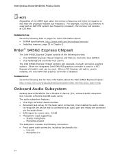
...=chips_body+desk Onboard Audio Subsystem Desktop Board D945GCNL has a flexible 6-channel (5.1) onboard audio subsystem that is connected to an audio port and retask the connector via the audio driver. • S/N (signal-to the following links or pages for more information about: • SDRAM specifications, http://www.intel.com/technology/memory/ • Installing memory, page 32 in 14 Intel Desktop Board D945GCNL Product Guide...
...=chips_body+desk Onboard Audio Subsystem Desktop Board D945GCNL has a flexible 6-channel (5.1) onboard audio subsystem that is connected to an audio port and retask the connector via the audio driver. • S/N (signal-to the following links or pages for more information about: • SDRAM specifications, http://www.intel.com/technology/memory/ • Installing memory, page 32 in 14 Intel Desktop Board D945GCNL Product Guide...
Product Guide
Page 15
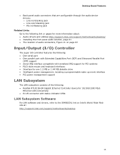
Desktop Board Features • Back panel audio connectors that are configurable through the audio device drivers: ― Line in/retasking jack ― Line out/retasking jack ― Mic in/retasking jack Related Links: Go to the following link or pages for more information about: • Audio drivers and utilities http://support.intel.com/support/motherboards/desktop/ • Installing... with status indicator LEDs LAN Subsystem Software For LAN software and drivers, refer to the D945GCNL link on Intel's World Wide Web site at: http://support.intel.com/support/motherboards/desktop 15
Desktop Board Features • Back panel audio connectors that are configurable through the audio device drivers: ― Line in/retasking jack ― Line out/retasking jack ― Mic in/retasking jack Related Links: Go to the following link or pages for more information about: • Audio drivers and utilities http://support.intel.com/support/motherboards/desktop/ • Installing... with status indicator LEDs LAN Subsystem Software For LAN software and drivers, refer to the D945GCNL link on Intel's World Wide Web site at: http://support.intel.com/support/motherboards/desktop 15
Product Guide
Page 23
.... 2 Installing and Replacing Desktop Board Components This chapter tells you how to: • Install the I/O shield • Install and remove the desktop board • Install and remove a processor • Install and remove memory • Install and remove a PCI Express x16 card • Connect the IDE and Serial ATA cables • Connect to the internal headers • Connect the flexible audio system...
.... 2 Installing and Replacing Desktop Board Components This chapter tells you how to: • Install the I/O shield • Install and remove the desktop board • Install and remove a processor • Install and remove memory • Install and remove a PCI Express x16 card • Connect the IDE and Serial ATA cables • Connect to the internal headers • Connect the flexible audio system...
Product Guide
Page 41
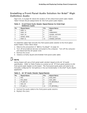
.... Refer to Table 5 below to connect an AC '97 front panel solution to the front panel audio header on the AC '97 audio specification. Installing and Replacing Desktop Board Components Installing a Front Panel Audio Solution for Intel High Definition Audio Pin Signal Name 1 PORT 1L 3 PORT 1R 5 PORT 2R 7 SENSE_SEND 9 PORT 2L Pin Signal Name 2 GND 4 PRESENCE# 6 SENSE1_RETURN 8 KEY...
.... Refer to Table 5 below to connect an AC '97 front panel solution to the front panel audio header on the AC '97 audio specification. Installing and Replacing Desktop Board Components Installing a Front Panel Audio Solution for Intel High Definition Audio Pin Signal Name 1 PORT 1L 3 PORT 1R 5 PORT 2R 7 SENSE_SEND 9 PORT 2L Pin Signal Name 2 GND 4 PRESENCE# 6 SENSE1_RETURN 8 KEY...
Product Guide
Page 43
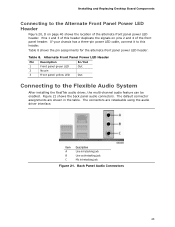
... shows the location of this header. Item Description A Line in/retasking jack B Line out/retasking jack C Mic in the table. Installing and Replacing Desktop Board Components Connecting to the Alternate Front Panel Power LED Header Figure 20, D on pins 2 and 4 of the front panel header.... power LED header. Back Panel Audio Connectors 43 Figure 21 shows the back panel audio connectors. If your chassis has a three-pin power LED cable, connect it to the Flexible Audio System After installing the RealTek audio driver, the multi-channel audio feature can be enabled. Table ...
... shows the location of this header. Item Description A Line in/retasking jack B Line out/retasking jack C Mic in the table. Installing and Replacing Desktop Board Components Connecting to the Alternate Front Panel Power LED Header Figure 20, D on pins 2 and 4 of the front panel header.... power LED header. Back Panel Audio Connectors 43 Figure 21 shows the back panel audio connectors. If your chassis has a three-pin power LED cable, connect it to the Flexible Audio System After installing the RealTek audio driver, the multi-channel audio feature can be enabled. Table ...

Product Specification
Page 41
... Device Function Number (hex) Number (hex) Number (hex) Description 00 00 00 Memory controller of Intel 82945GC component 00 01 00 PCI Express x16 graphics port (Note 1) 00 02 00 Integrated graphics controller 00 1B 00... High Definition Audio Controller 00 1C 00 PCI Express port 1 00 1D 00 USB UHCI controller 1 00 1D 01 USB UHCI...2) 08 00 LAN PLC 01 00 00 PCI Express video controller (if present) Notes: 1. Bus number is installed. 2. Table 11.
... Device Function Number (hex) Number (hex) Number (hex) Description 00 00 00 Memory controller of Intel 82945GC component 00 01 00 PCI Express x16 graphics port (Note 1) 00 02 00 Integrated graphics controller 00 1B 00... High Definition Audio Controller 00 1C 00 PCI Express port 1 00 1D 00 USB UHCI controller 1 00 1D 01 USB UHCI...2) 08 00 LAN PLC 01 00 00 PCI Express video controller (if present) Notes: 1. Bus number is installed. 2. Table 11.


