
Product Guide
Page 6
Intel Desktop Board D945GCNL Product Guide Installing the Processor Fan Heat Sink 30 Connecting the Processor Fan Heat Sink Cable 31 Removing the Processor 31 Installing and Removing Memory ...) Cable 39 Connecting to Internal Headers 40 Installing a Front Panel Audio Solution for Intel® High Definition Audio 41 Connecting to the USB 2.0 Headers 42 Connecting to the Front Panel Header 42 Connecting to the Alternate Front Panel Power LED Header 43 Connecting to the Flexible Audio System 43 Connecting Chassis Fan and Power Cables 44 Connecting...
Intel Desktop Board D945GCNL Product Guide Installing the Processor Fan Heat Sink 30 Connecting the Processor Fan Heat Sink Cable 31 Removing the Processor 31 Installing and Removing Memory ...) Cable 39 Connecting to Internal Headers 40 Installing a Front Panel Audio Solution for Intel® High Definition Audio 41 Connecting to the USB 2.0 Headers 42 Connecting to the Front Panel Header 42 Connecting to the Alternate Front Panel Power LED Header 43 Connecting to the Flexible Audio System 43 Connecting Chassis Fan and Power Cables 44 Connecting...
Product Guide
Page 7
... a DIMM 34 16. Installing a PCI Express x16 Card 36 17. Back Panel Audio Connectors 43 22. Safety Standards 59 13. Desktop Board D945GCNL Components 11 2. Installing the I/O Shield 25 5. Dual Channel Memory Configuration Example...Intel High Definition Audio 41 5. EMC Regulations 65 15. Desktop Board D945GCNL Mounting Screw Hole Locations 26 6. Lift the Load Plate 28 8. Internal Headers 40 21. Location of Chassis Fan Headers 44 23. Alternate Front Panel Power LED Header 43 9. Connecting the IDE Cable 38 19. Feature Summary 9 2. Desktop Board D945GCNL...
... a DIMM 34 16. Installing a PCI Express x16 Card 36 17. Back Panel Audio Connectors 43 22. Safety Standards 59 13. Desktop Board D945GCNL Components 11 2. Installing the I/O Shield 25 5. Dual Channel Memory Configuration Example...Intel High Definition Audio 41 5. EMC Regulations 65 15. Desktop Board D945GCNL Mounting Screw Hole Locations 26 6. Lift the Load Plate 28 8. Internal Headers 40 21. Location of Chassis Fan Headers 44 23. Alternate Front Panel Power LED Header 43 9. Connecting the IDE Cable 38 19. Feature Summary 9 2. Desktop Board D945GCNL...

Product Guide
Page 9
...Intel® Desktop Board D945GCNL. 1 Desktop Board Features This chapter briefly describes the main features of the desktop board. Feature Summary Form Factor Processor Main Memory Chipset Graphics Audio Expansion Capabilities Peripheral Interfaces microATX (243.84 millimeters [9.60 inches] x 243.84 millimeters [9.60 inches]) Support for an Intel...Definition Audio interface ― Realtek* ALC888 audio codec • One PCI Express x1 connector • One PCI Express x16 connector • Two PCI* connectors • Up to eight USB 2.0 ports ― Four ports routed to the back panel ...
...Intel® Desktop Board D945GCNL. 1 Desktop Board Features This chapter briefly describes the main features of the desktop board. Feature Summary Form Factor Processor Main Memory Chipset Graphics Audio Expansion Capabilities Peripheral Interfaces microATX (243.84 millimeters [9.60 inches] x 243.84 millimeters [9.60 inches]) Support for an Intel...Definition Audio interface ― Realtek* ALC888 audio codec • One PCI Express x1 connector • One PCI Express x16 connector • Two PCI* connectors • Up to eight USB 2.0 ports ― Four ports routed to the back panel ...
Product Guide
Page 12
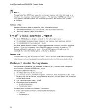
... 2.0 headers Alternate front panel power LED header Battery BIOS configuration jumper block Related Links: Go to the following links for more information about: • Desktop Board D945GCNL • Supported processors • Audio software and utilities • LAN software and drivers http://www.intel.com/design/motherbd http://support.intel.com/support/motherboards/desktop http://www.intel.com/go/FindCPU http...
... 2.0 headers Alternate front panel power LED header Battery BIOS configuration jumper block Related Links: Go to the following links for more information about: • Desktop Board D945GCNL • Supported processors • Audio software and utilities • LAN software and drivers http://www.intel.com/design/motherbd http://support.intel.com/support/motherboards/desktop http://www.intel.com/go/FindCPU http...
Product Guide
Page 14
... ― Microphone boost The subsystem includes the following connectors: • Front panel audio connector, including functionality for more information about the Intel 945GC Express Chipset: http://www.intel.com/products/desktop/chipsets/index.htm?iid=chips_body+desk Onboard Audio Subsystem Desktop Board D945GCNL has a flexible 6-channel (5.1) onboard audio subsystem that is used or a PCI Express x16 add-in card can...
... ― Microphone boost The subsystem includes the following connectors: • Front panel audio connector, including functionality for more information about the Intel 945GC Express Chipset: http://www.intel.com/products/desktop/chipsets/index.htm?iid=chips_body+desk Onboard Audio Subsystem Desktop Board D945GCNL has a flexible 6-channel (5.1) onboard audio subsystem that is used or a PCI Express x16 add-in card can...
Product Guide
Page 15
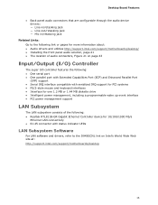
Desktop Board Features • Back panel audio connectors that are configurable through the audio device drivers: ― Line in/retasking jack ― Line out/retasking jack ― Mic in/retasking jack Related Links: Go to the following link or pages for more information about: • Audio drivers and utilities http://support.intel.com/support/motherboards/desktop... • RJ-45 connector with status indicator LEDs LAN Subsystem Software For LAN software and drivers, refer to the D945GCNL link on Intel's World Wide Web site at: http://support.intel.com/support/motherboards/desktop 15
Desktop Board Features • Back panel audio connectors that are configurable through the audio device drivers: ― Line in/retasking jack ― Line out/retasking jack ― Mic in/retasking jack Related Links: Go to the following link or pages for more information about: • Audio drivers and utilities http://support.intel.com/support/motherboards/desktop... • RJ-45 connector with status indicator LEDs LAN Subsystem Software For LAN software and drivers, refer to the D945GCNL link on Intel's World Wide Web site at: http://support.intel.com/support/motherboards/desktop 15
Product Guide
Page 23
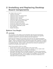
...any of the computer chassis. 23 Some circuitry on the board can continue to operate even though the front panel power button is not available, you how to: • Install the I/O shield • Install and remove the desktop board • Install and remove a processor • Install ...and remove memory • Install and remove a PCI Express x16 card • Connect the IDE and Serial ATA cables • Connect to the internal headers • Connect the flexible audio system • Connect...
...any of the computer chassis. 23 Some circuitry on the board can continue to operate even though the front panel power button is not available, you how to: • Install the I/O shield • Install and remove the desktop board • Install and remove a processor • Install ...and remove memory • Install and remove a PCI Express x16 card • Connect the IDE and Serial ATA cables • Connect to the internal headers • Connect the flexible audio system • Connect...

Product Guide
Page 40
Internal Headers 40 Item Description A Front panel audio B USB 2.0 C Front panel D Alternate front panel power LED Figure 20. Figure 20 shows the location of the internal headers. Intel Desktop Board D945GCNL Product Guide Connecting to Internal Headers Before connecting cables to the internal headers, observe the precautions in "Before You Begin" on page 23.
Internal Headers 40 Item Description A Front panel audio B USB 2.0 C Front panel D Alternate front panel power LED Figure 20. Figure 20 shows the location of the internal headers. Intel Desktop Board D945GCNL Product Guide Connecting to Internal Headers Before connecting cables to the internal headers, observe the precautions in "Before You Begin" on page 23.
Product Guide
Page 41
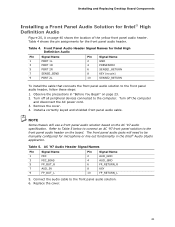
... Name 1 MIC 3 MIC_BIAS 5 FP_OUT_R 7 AUD_5V 9 FP_OUT_L Pin Signal Name 2 AUD_GND 4 AUD_GND 6 FP_RETURN_R 8 KEY 10 FP_RETURN_L 5. Connect the audio cable to the front panel audio solution. 6. Installing and Replacing Desktop Board Components Installing a Front Panel Audio Solution for Intel High Definition Audio Pin Signal Name 1 PORT 1L 3 PORT 1R 5 PORT 2R 7 SENSE_SEND 9 PORT 2L Pin Signal Name 2 GND 4 PRESENCE# 6 SENSE1_RETURN...
... Name 1 MIC 3 MIC_BIAS 5 FP_OUT_R 7 AUD_5V 9 FP_OUT_L Pin Signal Name 2 AUD_GND 4 AUD_GND 6 FP_RETURN_R 8 KEY 10 FP_RETURN_L 5. Connect the audio cable to the front panel audio solution. 6. Installing and Replacing Desktop Board Components Installing a Front Panel Audio Solution for Intel High Definition Audio Pin Signal Name 1 PORT 1L 3 PORT 1R 5 PORT 2R 7 SENSE_SEND 9 PORT 2L Pin Signal Name 2 GND 4 PRESENCE# 6 SENSE1_RETURN...

Product Guide
Page 42
.... Table 6. Replace the cover. Table 6 shows the pin assignments for the front panel header. Connecting to the USB 2.0 Headers Before connecting to the front panel header, observe the precautions in "Before You Begin" on page 23. Intel Desktop Board D945GCNL Product Guide To restore back panel audio, follow these steps: 1. Turn off all peripheral devices connected to +5 V Out...
.... Table 6. Replace the cover. Table 6 shows the pin assignments for the front panel header. Connecting to the USB 2.0 Headers Before connecting to the front panel header, observe the precautions in "Before You Begin" on page 23. Intel Desktop Board D945GCNL Product Guide To restore back panel audio, follow these steps: 1. Turn off all peripheral devices connected to +5 V Out...
Product Guide
Page 43
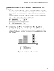
... B Line out/retasking jack C Mic in the table. Installing and Replacing Desktop Board Components Connecting to the Alternate Front Panel Power LED Header Figure 20, D on pins 2 and 4 of the alternate front panel power LED header. Pins 1 and 3 of this header. Back Panel Audio Connectors 43 If your chassis has a three-pin power LED cable, connect...
... B Line out/retasking jack C Mic in the table. Installing and Replacing Desktop Board Components Connecting to the Alternate Front Panel Power LED Header Figure 20, D on pins 2 and 4 of the alternate front panel power LED header. Pins 1 and 3 of this header. Back Panel Audio Connectors 43 If your chassis has a three-pin power LED cable, connect...

Product Specification
Page 7
Back Panel Audio Connector Options 25 4. Thermal Sensors and Fan Headers 29 6. Localized High Temperature Zones 60 Tables 1. System Memory Map 39 9. I/O Map 40 11. PCI Interrupt Routing Map 43 14. Detailed System Memory Address Map 38 8. Board Components Shown... Product Ecology Statements 79 5.1.4 EMC Regulations 83 5.1.5 Product Certification Markings (Board Level 85 5.2 Battery Disposal Information 86 Figures 1. Connection Diagram for Front Panel USB Headers 53 12. Back Panel Connectors 45 9. Power States and Targeted System Power 31 7. Contents 5 ...
Back Panel Audio Connector Options 25 4. Thermal Sensors and Fan Headers 29 6. Localized High Temperature Zones 60 Tables 1. System Memory Map 39 9. I/O Map 40 11. PCI Interrupt Routing Map 43 14. Detailed System Memory Address Map 38 8. Board Components Shown... Product Ecology Statements 79 5.1.4 EMC Regulations 83 5.1.5 Product Certification Markings (Board Level 85 5.2 Battery Disposal Information 86 Figures 1. Connection Diagram for Front Panel USB Headers 53 12. Back Panel Connectors 45 9. Power States and Targeted System Power 31 7. Contents 5 ...

Product Specification
Page 13
Table 2. Board Components Shown in Figure 1 Item/callout from Figure 1 Description A Front panel audio header B PCI Conventional bus add-in card connector #2 C PCI Conventional bus add-in card connector #1 D PCI Express x1 bus add-in card connector E PCI Express x16 bus add-in card connector F Back panel connectors G Processor core power connector H Processor fan header...
Table 2. Board Components Shown in Figure 1 Item/callout from Figure 1 Description A Front panel audio header B PCI Conventional bus add-in card connector #2 C PCI Conventional bus add-in card connector #1 D PCI Express x1 bus add-in card connector E PCI Express x16 bus add-in card connector F Back panel connectors G Processor core power connector H Processor fan header...
Product Specification
Page 24
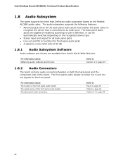
... panel audio header The back panel audio connectors Refer to -noise (S/N) ratio of 95 dB 1.8.1 Audio Subsystem Software Audio software and drivers are capable of the board. For information about Obtaining audio software and drivers Refer to an audio port. The back panel audio jacks are available from Intel's World Wide Web site. Intel Desktop Board D945GCNL Technical Product Specification 1.8 Audio Subsystem The board supports the Intel High Definition audio...
... panel audio header The back panel audio connectors Refer to -noise (S/N) ratio of 95 dB 1.8.1 Audio Subsystem Software Audio software and drivers are capable of the board. For information about Obtaining audio software and drivers Refer to an audio port. The back panel audio jacks are available from Intel's World Wide Web site. Intel Desktop Board D945GCNL Technical Product Specification 1.8 Audio Subsystem The board supports the Intel High Definition audio...
Product Specification
Page 25
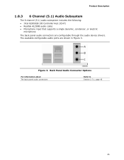
Figure 3. The available configurable audio ports are configurable through the audio device drivers. Back Panel Audio Connector Options For information about The back panel audio connectors Refer to Section 2.7.1, page 45 25 Product Description 1.8.3 6 Channel (5.1) Audio Subsystem The 6 channel (5.1) audio subsystem includes the following: • Intel 82801GB I/O Controller Hub (ICH7) • Realtek ALC888 audio codec • Microphone input that supports a single dynamic, condenser, or electret microphone The back panel audio connectors are shown in Figure 3.
Figure 3. The available configurable audio ports are configurable through the audio device drivers. Back Panel Audio Connector Options For information about The back panel audio connectors Refer to Section 2.7.1, page 45 25 Product Description 1.8.3 6 Channel (5.1) Audio Subsystem The 6 channel (5.1) audio subsystem includes the following: • Intel 82801GB I/O Controller Hub (ICH7) • Realtek ALC888 audio codec • Microphone input that supports a single dynamic, condenser, or electret microphone The back panel audio connectors are shown in Figure 3.

Product Specification
Page 45
2.7.1 Back Panel Connectors Figure 8 shows the location of the back panel connectors. Poor audio quality occurs if passive (non-amplified) speakers are connected to power headphones or amplified speakers only. Back Panel Connectors NOTE The back panel audio line out connector is designed to this output. 45 Technical Reference Item A B C D E F G H I J Description PS/2 mouse port PS/2 keyboard port Parallel port Serial port VGA port LAN USB ports [4] Audio line in Mic in Audio line out Figure 8.
2.7.1 Back Panel Connectors Figure 8 shows the location of the back panel connectors. Poor audio quality occurs if passive (non-amplified) speakers are connected to power headphones or amplified speakers only. Back Panel Connectors NOTE The back panel audio line out connector is designed to this output. 45 Technical Reference Item A B C D E F G H I J Description PS/2 mouse port PS/2 keyboard port Parallel port Serial port VGA port LAN USB ports [4] Audio line in Mic in Audio line out Figure 8.

Product Specification
Page 47
... N Serial ATA connector 1 O Serial ATA connector 3 P Serial ATA connector 2 Q Front panel header R Serial ATA connector 0 S Front panel USB header T Front panel USB header U Auxiliary front panel power LED header 47 Component-side Connectors and Headers Shown in Figure 9 Item/callout from Figure 9 Description A Front panel audio header B PCI Conventional bus add-in card connector 2 C PCI Conventional...
... N Serial ATA connector 1 O Serial ATA connector 3 P Serial ATA connector 2 Q Front panel header R Serial ATA connector 0 S Front panel USB header T Front panel USB header U Auxiliary front panel power LED header 47 Component-side Connectors and Headers Shown in Figure 9 Item/callout from Figure 9 Description A Front panel audio header B PCI Conventional bus add-in card connector 2 C PCI Conventional...

Product Specification
Page 48
...Name 1 Intruder 2 Ground Table 17. Front and Rear Chassis Fan Headers Pin Signal Name 1 FAN_CONTROL 2 +12 V 3 FAN_TACH 48 Front Panel Audio Header Pin Signal Name 1 Port E [Port 1] Left Channel 3 Port E [Port 1] Right Channel 5 Port F [Port 2] Right ...front panel audio header is colored yellow. Serial ATA Connectors Pin Signal Name 1 Ground 2 TXP 3 TXN 4 Ground 5 RXN 6 RXP 7 Ground Table 18. Table 16. Processor Fan Header Pin Signal Name 1 Ground 2 +12 V 3 FAN_TACH 4 FAN_CONTROL Table 19. Intel Desktop Board D945GCNL Technical ...
...Name 1 Intruder 2 Ground Table 17. Front and Rear Chassis Fan Headers Pin Signal Name 1 FAN_CONTROL 2 +12 V 3 FAN_TACH 48 Front Panel Audio Header Pin Signal Name 1 Port E [Port 1] Left Channel 3 Port E [Port 1] Right Channel 5 Port F [Port 2] Right ...front panel audio header is colored yellow. Serial ATA Connectors Pin Signal Name 1 Ground 2 TXP 3 TXN 4 Ground 5 RXN 6 RXP 7 Ground Table 18. Table 16. Processor Fan Header Pin Signal Name 1 Ground 2 +12 V 3 FAN_TACH 4 FAN_CONTROL Table 19. Intel Desktop Board D945GCNL Technical ...


