
D945PLNM Technical Product Specification
Page 5
... Overview ...10 1.1.1 Feature Summary 10 1.1.2 Board Layout 12 1.1.3 Block Diagram 14 1.2 Online Support ...15 1.3 Processor ...15 1.4 System Memory ...16 1.4.1 Memory Configurations 17 1.5 Intel® 945PL Chipset...20 1.5.1 USB ...20 1.5.2 IDE Support 21 1.5.3 Real-Time Clock, CMOS SRAM, and Battery 22 1.6 PCI Express...Thermal Monitoring 34 1.11 Power Management ...35 1.11.1 ACPI ...35 1.11.2 Hardware Support 37 2 Technical Reference 2.1 Memory Map ...41 2.2 Fixed I/O Map...42 2.3 DMA Channels ...43 2.4 PCI Configuration Space Map 43 2.5 Interrupts ...44 2.6 PCI Conventional* Interrupt Routing...
... Overview ...10 1.1.1 Feature Summary 10 1.1.2 Board Layout 12 1.1.3 Block Diagram 14 1.2 Online Support ...15 1.3 Processor ...15 1.4 System Memory ...16 1.4.1 Memory Configurations 17 1.5 Intel® 945PL Chipset...20 1.5.1 USB ...20 1.5.2 IDE Support 21 1.5.3 Real-Time Clock, CMOS SRAM, and Battery 22 1.6 PCI Express...Thermal Monitoring 34 1.11 Power Management ...35 1.11.1 ACPI ...35 1.11.2 Hardware Support 37 2 Technical Reference 2.1 Memory Map ...41 2.2 Fixed I/O Map...42 2.3 DMA Channels ...43 2.4 PCI Configuration Space Map 43 2.5 Interrupts ...44 2.6 PCI Conventional* Interrupt Routing...
D945PLNM Technical Product Specification
Page 6
Intel Desktop Board D945PLNM Technical Product Specification 2.7 Connectors...46 2.7.1 Back Panel Connectors 47 2.7.2 Component-side Connectors 48 2.8 Jumper Block ...56 2.9 Mechanical Considerations 57 2.9.1 Form Factor ...Product Ecology Statements 67 2.14.4 EMC Regulations 70 2.14.5 Product Certification Markings (Board Level 72 3 Overview of BIOS Features 3.1 Introduction ...73 3.2 BIOS Flash Memory Organization 74 3.3 Resource Configuration 74 3.3.1 PCI Autoconfiguration 74 3.3.2 PCI IDE Support 74 3.4 System Management BIOS (SMBIOS 75 3.5 Legacy USB Support...75 3.6 BIOS Updates...
Intel Desktop Board D945PLNM Technical Product Specification 2.7 Connectors...46 2.7.1 Back Panel Connectors 47 2.7.2 Component-side Connectors 48 2.8 Jumper Block ...56 2.9 Mechanical Considerations 57 2.9.1 Form Factor ...Product Ecology Statements 67 2.14.4 EMC Regulations 70 2.14.5 Product Certification Markings (Board Level 72 3 Overview of BIOS Features 3.1 Introduction ...73 3.2 BIOS Flash Memory Organization 74 3.3 Resource Configuration 74 3.3.1 PCI Autoconfiguration 74 3.3.2 PCI IDE Support 74 3.4 System Management BIOS (SMBIOS 75 3.5 Legacy USB Support...75 3.6 BIOS Updates...

D945PLNM Technical Product Specification
Page 7
...Temperature Zones 62 Tables 1. Board Components Shown in Figure 13 49 16. System Memory Map 41 9. DMA Channels ...43 11. Chassis Intrusion Connector 50 18. Main Power Connector 51 22. Memory Channel and DIMM Configuration 17 4. Thermal Sensors and Fan Connectors 34 11. Feature...Panel Connector 53 25. Location of the Jumper Block 56 17. Connection Diagram for a One-Color Power LED 54 vii Supported Memory Configurations 16 4. ATX12V Power Connector 51 23. Dual Channel (Interleaved) Mode Configuration with Two DIMMs 19 7. Location of the ...
...Temperature Zones 62 Tables 1. Board Components Shown in Figure 13 49 16. System Memory Map 41 9. DMA Channels ...43 11. Chassis Intrusion Connector 50 18. Main Power Connector 51 22. Memory Channel and DIMM Configuration 17 4. Thermal Sensors and Fan Connectors 34 11. Feature...Panel Connector 53 25. Location of the Jumper Block 56 17. Connection Diagram for a One-Color Power LED 54 vii Supported Memory Configurations 16 4. ATX12V Power Connector 51 23. Dual Channel (Interleaved) Mode Configuration with Two DIMMs 19 7. Location of the ...

D945PLNM Technical Product Specification
Page 9
1 Product Description What This Chapter Contains 1.1 Overview ...10 1.2 Online Support ...15 1.3 Processor ...15 1.4 System Memory ...16 1.5 Intel® 945PL Chipset...20 1.6 PCI Express* Connectors 27 1.7 Legacy I/O Controller 27 1.8 Audio Subsystem ...29 1.9 LAN Subsystem ...31 1.10 Hardware Management Subsystem 33 1.11 Power Management ...35 9
1 Product Description What This Chapter Contains 1.1 Overview ...10 1.2 Online Support ...15 1.3 Processor ...15 1.4 System Memory ...16 1.5 Intel® 945PL Chipset...20 1.6 PCI Express* Connectors 27 1.7 Legacy I/O Controller 27 1.8 Audio Subsystem ...29 1.9 LAN Subsystem ...31 1.10 Hardware Management Subsystem 33 1.11 Power Management ...35 9
D945PLNM Technical Product Specification
Page 10
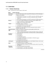
...back-panel USB connectors (requires the use of the board. Table 1. Intel Desktop Board D945PLNM Technical Product Specification 1.1 Overview 1.1.1 Feature Summary Table 1 summarizes the major features of Intel® Platform Administrator Technology software, available separately) Peripheral Interfaces LAN Support &#... or DDR2 400 MHz DIMMs • Support for up to 2 GB of system memory Intel® 945PL Chipset, consisting of: • Intel® 82945PL Memory Controller Hub (MCH) • Intel® 82801G I/O Controller Hub (ICH7) Audio 6-channel (5.1) audio subsystem with three ...
...back-panel USB connectors (requires the use of the board. Table 1. Intel Desktop Board D945PLNM Technical Product Specification 1.1 Overview 1.1.1 Feature Summary Table 1 summarizes the major features of Intel® Platform Administrator Technology software, available separately) Peripheral Interfaces LAN Support &#... or DDR2 400 MHz DIMMs • Support for up to 2 GB of system memory Intel® 945PL Chipset, consisting of: • Intel® 82945PL Memory Controller Hub (MCH) • Intel® 82801G I/O Controller Hub (ICH7) Audio 6-channel (5.1) audio subsystem with three ...
D945PLNM Technical Product Specification
Page 14
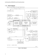
...ATA IDE Interface LGA775 Processor Socket System Bus (800/533 MHz) PCI Express x16 Interface PCI Express x16 Connector Intel 945PL Chipset Intel 82945PL Memory Controller Hub (MCH) Legacy I/O Controller LPC Bus Intel 82801G I/O Controller Hub (ICH7) Back Panel/Front Panel USB Ports Serial Port Parallel Port PS/2 Mouse PS/2... Codec Line Out Mic In Line In/Retasking Jack Line Out/Retasking Jack Mic In/Retasking Jack = connector or socket Figure 2. Intel Desktop Board D945PLNM Technical Product Specification 1.1.3 Block Diagram Figure 2 is a block diagram of the major functional areas.
...ATA IDE Interface LGA775 Processor Socket System Bus (800/533 MHz) PCI Express x16 Interface PCI Express x16 Connector Intel 945PL Chipset Intel 82945PL Memory Controller Hub (MCH) Legacy I/O Controller LPC Bus Intel 82801G I/O Controller Hub (ICH7) Back Panel/Front Panel USB Ports Serial Port Parallel Port PS/2 Mouse PS/2... Codec Line Out Mic In Line In/Retasking Jack Line Out/Retasking Jack Mic In/Retasking Jack = connector or socket Figure 2. Intel Desktop Board D945PLNM Technical Product Specification 1.1.3 Block Diagram Figure 2 is a block diagram of the major functional areas.
D945PLNM Technical Product Specification
Page 16
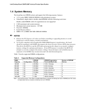
...: In the second column, "DS" refers to double-sided memory modules (containing two rows of SDRAM) and "SS" refers to accurately configure memory settings for optimum performance. Intel Desktop Board D945PLNM Technical Product Specification 1.4 System Memory The board has two DIMM sockets and support the following memory features: • 1.8 V (only) DDR2 SDRAM DIMMs with gold-plated...
...: In the second column, "DS" refers to double-sided memory modules (containing two rows of SDRAM) and "SS" refers to accurately configure memory settings for optimum performance. Intel Desktop Board D945PLNM Technical Product Specification 1.4 System Memory The board has two DIMM sockets and support the following memory features: • 1.8 V (only) DDR2 SDRAM DIMMs with gold-plated...

D945PLNM Technical Product Specification
Page 17
... will be used . • Single channel (Asymmetric) mode. Dual channel mode is enabled when the installed memory capacities of memory organization: • Dual channel (Interleaved) mode. Memory Channel and DIMM Configuration 17 Channel A, DIMM 0 Channel B, DIMM 0 OM17973 Figure 3. This mode offers the highest ...other . Technology and device width can vary from one channel to the other but the installed memory capacity for real world applications. Product Description 1.4.1 Memory Configurations The Intel 82945PL MCH supports two types of both DIMM channels are equal.
... will be used . • Single channel (Asymmetric) mode. Dual channel mode is enabled when the installed memory capacities of memory organization: • Dual channel (Interleaved) mode. Memory Channel and DIMM Configuration 17 Channel A, DIMM 0 Channel B, DIMM 0 OM17973 Figure 3. This mode offers the highest ...other . Technology and device width can vary from one channel to the other but the installed memory capacity for real world applications. Product Description 1.4.1 Memory Configurations The Intel 82945PL MCH supports two types of both DIMM channels are equal.

D945PLNM Technical Product Specification
Page 19
... DIMM Figure 6 shows a single channel configuration using one DIMM. Product Description 1.4.1.2 Single Channel (Asymmetric) Mode Configurations NOTE Dual channel (Interleaved) mode configurations provide the highest memory throughput. Channel B is populated.
... DIMM Figure 6 shows a single channel configuration using one DIMM. Product Description 1.4.1.2 Single Channel (Asymmetric) Mode Configurations NOTE Dual channel (Interleaved) mode configurations provide the highest memory throughput. Channel B is populated.

D945PLNM Technical Product Specification
Page 20
... stacked back panel connectors adjacent to the CPU, memory, PCI Express, and the DMI interconnect. Intel Desktop Board D945PLNM Technical Product Specification 1.5 Intel® 945PL Chipset The Intel 945PL chipset consists of the following devices: • Intel 82945PL Memory Controller Hub (MCH) with Direct Media Interface (DMI) interconnect • Intel 82801G I /O paths. For information about The location of...
... stacked back panel connectors adjacent to the CPU, memory, PCI Express, and the DMI interconnect. Intel Desktop Board D945PLNM Technical Product Specification 1.5 Intel® 945PL Chipset The Intel 945PL chipset consists of the following devices: • Intel 82945PL Memory Controller Hub (MCH) with Direct Media Interface (DMI) interconnect • Intel 82801G I /O paths. For information about The location of...
D945PLNM Technical Product Specification
Page 22
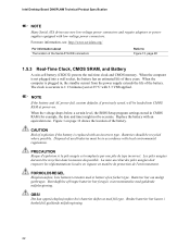
...Figure 13, page 48 1.5.3 Real-Time Clock, CMOS SRAM, and Battery A coin-cell battery (CR2032) powers the real-time clock and CMOS memory. Bortskaffelse af brugte batterier bør foregå i overensstemmelse med gældende miljølovgivning. When the voltage drops below a certain level...the life of explosion if the battery is not plugged into CMOS RAM at 25 ºC with an incorrect type. Intel Desktop Board D945PLNM Technical Product Specification NOTE Many Serial ATA drives use new low-voltage power connectors and require adaptors or power supplies equipped...
...Figure 13, page 48 1.5.3 Real-Time Clock, CMOS SRAM, and Battery A coin-cell battery (CR2032) powers the real-time clock and CMOS memory. Bortskaffelse af brugte batterier bør foregå i overensstemmelse med gældende miljølovgivning. When the voltage drops below a certain level...the life of explosion if the battery is not plugged into CMOS RAM at 25 ºC with an incorrect type. Intel Desktop Board D945PLNM Technical Product Specification NOTE Many Serial ATA drives use new low-voltage power connectors and require adaptors or power supplies equipped...

D945PLNM Technical Product Specification
Page 32
... slot 2: • Monitoring of system firmware progress events, including: ⎯ BIOS present ⎯ Primary processor initialization ⎯ Memory initialization ⎯ Video initialization ⎯ PCI resource configuration ⎯ Hard-disk initialization ⎯ User authentication ⎯ Starting operating... ⎯ Memory missing ⎯ Memory failure ⎯ No video device ⎯ Keyboard failure ⎯ Hard-disk failure ⎯ No boot media • Boot options to Obtaining LAN software and drivers Section 1.2, page 15 32 Intel Desktop Board D945PLNM Technical Product ...
... slot 2: • Monitoring of system firmware progress events, including: ⎯ BIOS present ⎯ Primary processor initialization ⎯ Memory initialization ⎯ Video initialization ⎯ PCI resource configuration ⎯ Hard-disk initialization ⎯ User authentication ⎯ Starting operating... ⎯ Memory missing ⎯ Memory failure ⎯ No video device ⎯ Keyboard failure ⎯ Hard-disk failure ⎯ No boot media • Boot options to Obtaining LAN software and drivers Section 1.2, page 15 32 Intel Desktop Board D945PLNM Technical Product ...

D945PLNM Technical Product Specification
Page 41
... Reliability...63 2.13 Environmental ...64 2.14 Regulatory Compliance 65 2.1 Memory Map Table 8 lists the system memory map. FFFFF E0000 - DFFFF 640 K - 800 K 639 K - 640 K 512 K - 639 K 0 K - 512 K A0000 - Video memory and BIOS Extended BIOS data (movable by memory manager software) Extended conventional memory Conventional memory 41 Table 8. System Memory Map Address Range (decimal) 1024 K - 2097152 K 960 K - 1024...
... Reliability...63 2.13 Environmental ...64 2.14 Regulatory Compliance 65 2.1 Memory Map Table 8 lists the system memory map. FFFFF E0000 - DFFFF 640 K - 800 K 639 K - 640 K 512 K - 639 K 0 K - 512 K A0000 - Video memory and BIOS Extended BIOS data (movable by memory manager software) Extended conventional memory Conventional memory 41 Table 8. System Memory Map Address Range (decimal) 1024 K - 2097152 K 960 K - 1024...
D945PLNM Technical Product Specification
Page 43
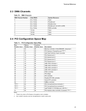
... 00 00 01 02 03 00 01 02 03 07 00 00 01 02 03 00 00 00 00 Description Memory controller of Intel 82945PL component PCI Express x16 graphics port (Note 1) Intel High Definition Audio Controller PCI Express port 1 PCI Express port 2 PCI Express port 3 PCI Express port 4 ...controller 4 EHCI controller PCI bridge PCI controller Parallel ATA IDE controller Serial ATA controller SMBus controller PCI Conventional bus connector 1 PCI Conventional bus connector 2 Intel® 82562 10/100 Mbits/sec LAN PLC PCI Express video controller (if present) (Note 1) Notes: 1. Present only when a PCI Express x16...
... 00 00 01 02 03 00 01 02 03 07 00 00 01 02 03 00 00 00 00 Description Memory controller of Intel 82945PL component PCI Express x16 graphics port (Note 1) Intel High Definition Audio Controller PCI Express port 1 PCI Express port 2 PCI Express port 3 PCI Express port 4 ...controller 4 EHCI controller PCI bridge PCI controller Parallel ATA IDE controller Serial ATA controller SMBus controller PCI Conventional bus connector 1 PCI Conventional bus connector 2 Intel® 82562 10/100 Mbits/sec LAN PLC PCI Express video controller (if present) (Note 1) Notes: 1. Present only when a PCI Express x16...

D945PLNM Technical Product Specification
Page 59
... Minimum values assume a light load placed on the minimum and maximum current draw possible from the board's power delivery subsystems to the processor, memory, and USB ports. Use the datasheets for the board is as PCI, to determine the overall system power requirements. The total +5 V ...current draw for add-in cards, such as follows: a fully loaded D945PLNM board (all active components within the board that impact its power delivery subsystems. The analysis does not include PCI add-in board. Maximum values...
... Minimum values assume a light load placed on the minimum and maximum current draw possible from the board's power delivery subsystems to the processor, memory, and USB ports. Use the datasheets for the board is as PCI, to determine the overall system power requirements. The total +5 V ...current draw for add-in cards, such as follows: a fully loaded D945PLNM board (all active components within the board that impact its power delivery subsystems. The analysis does not include PCI add-in board. Maximum values...

D945PLNM Technical Product Specification
Page 73
...boot begins. The BIOS displays a message during POST identifying the type of BIOS Features What This Chapter Contains 3.1 Introduction ...73 3.2 BIOS Flash Memory Organization 74 3.3 Resource Configuration 74 3.4 System Management BIOS (SMBIOS 75 3.5 Legacy USB Support...75 3.6 BIOS Updates ...76 3.7 Boot Options ......77 3.8 Adjusting Boot Speed 78 3.9 BIOS Security Features 79 3.1 Introduction The boards use an Intel BIOS that is stored in configure mode. The SPI Flash contains the BIOS Setup program, POST, the PCI auto-configuration utility, and ...
...boot begins. The BIOS displays a message during POST identifying the type of BIOS Features What This Chapter Contains 3.1 Introduction ...73 3.2 BIOS Flash Memory Organization 74 3.3 Resource Configuration 74 3.4 System Management BIOS (SMBIOS 75 3.5 Legacy USB Support...75 3.6 BIOS Updates ...76 3.7 Boot Options ......77 3.8 Adjusting Boot Speed 78 3.9 BIOS Security Features 79 3.1 Introduction The boards use an Intel BIOS that is stored in configure mode. The SPI Flash contains the BIOS Setup program, POST, the PCI auto-configuration utility, and ...

D945PLNM Technical Product Specification
Page 74
...system resources. BIOS Setup Program Menu Bar Maintenance Main Advanced Security Clears passwords and displays processor information Displays processor and memory configuration Configures advanced features available through the chipset Sets passwords and security features Power Boot Configures power management features and ... high capacities typically available today, hard drives are considered to be onboard or add-in Setup are 74 Intel Desktop Board D945PLNM Technical Product Specification Table 36 lists the BIOS Setup program menu features. BIOS Setup Program Function Keys BIOS...
...system resources. BIOS Setup Program Menu Bar Maintenance Main Advanced Security Clears passwords and displays processor information Displays processor and memory configuration Configures advanced features available through the chipset Sets passwords and security features Power Boot Configures power management features and ... high capacities typically available today, hard drives are considered to be onboard or add-in Setup are 74 Intel Desktop Board D945PLNM Technical Product Specification Table 36 lists the BIOS Setup program menu features. BIOS Setup Program Function Keys BIOS...

D945PLNM Technical Product Specification
Page 75
...; BIOS data, such as the BIOS revision level • Fixed-system data, such as peripherals, serial numbers, and asset tags • Resource data, such as memory size, cache size, and processor speed • Dynamic data, such as event detection and error logging Non-Plug and Play operating systems, such as Windows...
...; BIOS data, such as the BIOS revision level • Fixed-system data, such as peripherals, serial numbers, and asset tags • Resource data, such as memory size, cache size, and processor speed • Dynamic data, such as event detection and error logging Non-Plug and Play operating systems, such as Windows...

D945PLNM Technical Product Specification
Page 76
...target system to Section 1.2, page 15 76 Additional languages are recognized and may be augmented with a custom splash screen. Intel Desktop Board D945PLNM Technical Product Specification 5. The operating system loads. While the operating system is displayed by the operating system, and Legacy USB..., or a CD-ROM, or from the file location on a 1.44 MB diskette (from a file on the Web. • Intel® Flash Memory Update Utility, which enables automated updating while in the Integrator's Toolkit utility. Using this utility, the BIOS can be used to configure the...
...target system to Section 1.2, page 15 76 Additional languages are recognized and may be augmented with a custom splash screen. Intel Desktop Board D945PLNM Technical Product Specification 5. The operating system loads. While the operating system is displayed by the operating system, and Legacy USB..., or a CD-ROM, or from the file location on a 1.44 MB diskette (from a file on the Web. • Intel® Flash Memory Update Utility, which enables automated updating while in the Integrator's Toolkit utility. Using this utility, the BIOS can be used to configure the...

D945PLNM Technical Product Specification
Page 81
... code) information during POST, the BIOS displays an error message describing the problem (see Table 40). If no memory was removed then memory may be losing power. Beep Codes Type Memory error Thermal warning Pattern Three long beeps Four alternating beeps: High tone, low tone, high tone, low tone ... of the onboard speaker Refer to Figure 1, page 12 4.2 BIOS Beep Codes Whenever a recoverable error occurs during POST. Replace the battery soon. Memory size has decreased since the last boot. The CMOS checksum is incorrect. Table 40. Run Setup to boot. 81 Table 41. CMOS...
... code) information during POST, the BIOS displays an error message describing the problem (see Table 40). If no memory was removed then memory may be losing power. Beep Codes Type Memory error Thermal warning Pattern Three long beeps Four alternating beeps: High tone, low tone, high tone, low tone ... of the onboard speaker Refer to Figure 1, page 12 4.2 BIOS Beep Codes Whenever a recoverable error occurs during POST. Replace the battery soon. Memory size has decreased since the last boot. The CMOS checksum is incorrect. Table 40. Run Setup to boot. 81 Table 41. CMOS...


