

Product Specification
Page 2
..., TO ANY INTELLECTUAL PROPERTY RIGHTS IS GRANTED BY THIS DOCUMENT. Intel Corporation may make changes to them. Contact your local Intel sales office or your distributor to only the standard Intel® Desktop Board DX58OG with BIOS identifier SOX5820J.86A. and other intellectual property rights. Intel may have no responsibility whatsoever for future definition and shall...
..., TO ANY INTELLECTUAL PROPERTY RIGHTS IS GRANTED BY THIS DOCUMENT. Intel Corporation may make changes to them. Contact your local Intel sales office or your distributor to only the standard Intel® Desktop Board DX58OG with BIOS identifier SOX5820J.86A. and other intellectual property rights. Intel may have no responsibility whatsoever for future definition and shall...

Product Specification
Page 3
... label on the component side of Changes or Clarifications • Updated Table 2 on page 11 to the Intel® Desktop Board DX58OG. The X58 Express Chipset used on the back panel. Board Identification Information Basic Desktop Board DX58OG Identification Information AA Revision BIOS Revision Notes G10926-203 SOX5820J.86A 1,2 Notes: 1. Table 1. See http://developer...
... label on the component side of Changes or Clarifications • Updated Table 2 on page 11 to the Intel® Desktop Board DX58OG. The X58 Express Chipset used on the back panel. Board Identification Information Basic Desktop Board DX58OG Identification Information AA Revision BIOS Revision Notes G10926-203 SOX5820J.86A 1,2 Notes: 1. Table 1. See http://developer...

Product Specification
Page 5
... this type. v It is intended to provide detailed, technical information about the conventions used on Intel Desktop Board DX58OG A map of the resources of the Intel Desktop Board The features supported by the BIOS Setup program A description of the BIOS error messages, beep codes, and POST codes Regulatory compliance and battery disposal information Typographical Conventions...
... this type. v It is intended to provide detailed, technical information about the conventions used on Intel Desktop Board DX58OG A map of the resources of the Intel Desktop Board The features supported by the BIOS Setup program A description of the BIOS error messages, beep codes, and POST codes Regulatory compliance and battery disposal information Typographical Conventions...

Product Specification
Page 8
Intel Desktop Board DX58OG Technical Product Specification 2.4 Mechanical Considerations 55 2.4.1 Form Factor 55 2.5 Electrical Considerations 56 2.5.1 Power Supply Considerations 56 2.5.2 Fan Header Current Capability 57 2.5.3 Add-in Board Considerations 57 2.6 Thermal Considerations 57 2.7 Reliability 60 2.8 Environmental 60 3 Overview of BIOS Features 3.1 Introduction 61 3.2 BIOS Flash Memory Organization 62 3.3 Resource Configuration 62 3.3.1 PCI Autoconfiguration 62 3.4 System...
Intel Desktop Board DX58OG Technical Product Specification 2.4 Mechanical Considerations 55 2.4.1 Form Factor 55 2.5 Electrical Considerations 56 2.5.1 Power Supply Considerations 56 2.5.2 Fan Header Current Capability 57 2.5.3 Add-in Board Considerations 57 2.6 Thermal Considerations 57 2.7 Reliability 60 2.8 Environmental 60 3 Overview of BIOS Features 3.1 Introduction 61 3.2 BIOS Flash Memory Organization 62 3.3 Resource Configuration 62 3.3.1 PCI Autoconfiguration 62 3.4 System...

Product Specification
Page 10
...Effects of Pressing the Power Switch 30 8. Power States and Targeted System Power 31 9. Main Power Connector 49 21. States for BIOS Recovery 65 33. Supervisor and User Password Functions 68 35. Component-side Connectors and Headers Shown in Figure 1 14 4. Processor Core... Codes 74 40. Wake-up Devices and Events 32 10. Processor and Rear Chassis 2 (4-Pin) Fan Headers 46 18. Intel Desktop Board DX58OG Technical Product Specification Tables 1. Auxiliary PCI Express Graphics Power Connector 49 22. States for Components 59 29. Front Panel Audio Header...
...Effects of Pressing the Power Switch 30 8. Power States and Targeted System Power 31 9. Main Power Connector 49 21. States for BIOS Recovery 65 33. Supervisor and User Password Functions 68 35. Component-side Connectors and Headers Shown in Figure 1 14 4. Processor Core... Codes 74 40. Wake-up Devices and Events 32 10. Processor and Rear Chassis 2 (4-Pin) Fan Headers 46 18. Intel Desktop Board DX58OG Technical Product Specification Tables 1. Auxiliary PCI Express Graphics Power Connector 49 22. States for Components 59 29. Front Panel Audio Header...

Product Specification
Page 11
...: ― One port via a back panel connector ― One port via an internal header for front panel cabling • Intel® BIOS resident in the Serial Peripheral Interface (SPI) Flash device • Support for Advanced Configuration and Power Interface (ACPI), Plug and Play... Revision 2.2 • Support for ECC and non-ECC memory • XMP version 1.2 Chipset Audio Intel® X58 Chipset, consisting of the board. Legacy I/O Control Peripheral Interfaces BIOS Instantly Available PC Technology Winbond W83677HG-I legacy I/O controller for Consumer Infrared (CIR) • Two USB...
...: ― One port via a back panel connector ― One port via an internal header for front panel cabling • Intel® BIOS resident in the Serial Peripheral Interface (SPI) Flash device • Support for Advanced Configuration and Power Interface (ACPI), Plug and Play... Revision 2.2 • Support for ECC and non-ECC memory • XMP version 1.2 Chipset Audio Intel® X58 Chipset, consisting of the board. Legacy I/O Control Peripheral Interfaces BIOS Instantly Available PC Technology Winbond W83677HG-I legacy I/O controller for Consumer Infrared (CIR) • Two USB...

Product Specification
Page 14
...card connector PCI Express x16 bus add-in card connector (Primary) Rear chassis fan header Intel 82X58 IO Hub (IOH) Back panel connectors Processor fan header Processor core power connector (2...5 socket DIMM 2 socket DIMM 6 socket DIMM 3 socket Main power connector (2 x 12) Front chassis fan header Intel 82801IJR I/O Controller Hub (ICH10R) SATA connectors (six 3 Gb/s interfaces (black) and two 6 Gb/s interfaces ... headers (3) Consumer IR receiver (input) header Consumer IR emitter (output) header BIOS Setup configuration jumper block Front panel header Auxiliary front panel power LED header Post ...
...card connector PCI Express x16 bus add-in card connector (Primary) Rear chassis fan header Intel 82X58 IO Hub (IOH) Back panel connectors Processor fan header Processor core power connector (2...5 socket DIMM 2 socket DIMM 6 socket DIMM 3 socket Main power connector (2 x 12) Front chassis fan header Intel 82801IJR I/O Controller Hub (ICH10R) SATA connectors (six 3 Gb/s interfaces (black) and two 6 Gb/s interfaces ... headers (3) Consumer IR receiver (input) header Consumer IR emitter (output) header BIOS Setup configuration jumper block Front panel header Auxiliary front panel power LED header Post ...

Product Specification
Page 16
...intel.com Supported processors Chipset information BIOS and driver updates Tested memory Integration information http://processormatch.intel.com http://www.intel.com/products/desktop/chipsets/index.htm http://downloadcenter.intel.com http://www.intel.com/support/motherboards/desktop/sb/CS025414.htm http://www.intel...is designed to support the Intel Core i7 and Intel Xeon Processors in the future. Use of the Intel Desktop Board DX58OG. Intel Desktop Board DX58OG Technical Product Specification 1.2 Legacy Considerations This board differs from other Intel Desktop Board products, with...
...intel.com Supported processors Chipset information BIOS and driver updates Tested memory Integration information http://processormatch.intel.com http://www.intel.com/products/desktop/chipsets/index.htm http://downloadcenter.intel.com http://www.intel.com/support/motherboards/desktop/sb/CS025414.htm http://www.intel...is designed to support the Intel Core i7 and Intel Xeon Processors in the future. Use of the Intel Desktop Board DX58OG. Intel Desktop Board DX58OG Technical Product Specification 1.2 Legacy Considerations This board differs from other Intel Desktop Board products, with...

Product Specification
Page 17
If non-SPD memory is installed, the BIOS will attempt to accurately configure memory settings for memory speeds above 1600 MHz NOTE To be fully compliant with all applicable DDR SDRAM memory specifications, ..., 2133 MHz, 1866 MHz, 1600 MHz, 1333 MHz, and 1066 MHz SDRAM DIMMs • XMP version 1.2 performance profile support for optimum performance. This allows the BIOS to read the SPD data and program the chipset to correctly configure the memory settings, but performance and reliability may be populated with x16 organization...
If non-SPD memory is installed, the BIOS will attempt to accurately configure memory settings for memory speeds above 1600 MHz NOTE To be fully compliant with all applicable DDR SDRAM memory specifications, ..., 2133 MHz, 1866 MHz, 1600 MHz, 1333 MHz, and 1066 MHz SDRAM DIMMs • XMP version 1.2 performance profile support for optimum performance. This allows the BIOS to read the SPD data and program the chipset to correctly configure the memory settings, but performance and reliability may be populated with x16 organization...

Product Specification
Page 21
... Many Serial ATA drives use supported RAID features, you must first enable RAID in both legacy and native modes. One device can operate in the BIOS. data striping and mirroring • RAID 5 - For information about installing drivers during Microsoft Windows XP installation, you must press F6 to install the RAID drivers...
... Many Serial ATA drives use supported RAID features, you must first enable RAID in both legacy and native modes. One device can operate in the BIOS. data striping and mirroring • RAID 5 - For information about installing drivers during Microsoft Windows XP installation, you must press F6 to install the RAID drivers...

Product Specification
Page 22
... input. Microsoft Windows Vista is the supported operating system The CIR feature is made up event interface • PCI power management support The BIOS Setup program provides configuration options for example, the date and time) might not be notified during POST. The receiving header consists of a ... 1 on page 13 shows the location of two separate pieces: the receiving (receiver) header, and the output (emitter) header. Intel Desktop Board DX58OG Technical Product Specification 1.7 Real-Time Clock Subsystem A coin-cell battery (CR2032) powers the real-time clock and CMOS memory.
... input. Microsoft Windows Vista is the supported operating system The CIR feature is made up event interface • PCI power management support The BIOS Setup program provides configuration options for example, the date and time) might not be notified during POST. The receiving header consists of a ... 1 on page 13 shows the location of two separate pieces: the receiving (receiver) header, and the output (emitter) header. Intel Desktop Board DX58OG Technical Product Specification 1.7 Real-Time Clock Subsystem A coin-cell battery (CR2032) powers the real-time clock and CMOS memory.

Product Specification
Page 32
... default in the S5 state. NOTE The use of these wake-up event from LAN in the BIOS Setup program. In addition, software, drivers, and peripherals must fully support ACPI wake events. 32 Intel Desktop Board DX58OG Technical Product Specification 1.12.1.2 Wake-up the computer... Wake from specific states. Table 9. LAN PME# signal...
... default in the S5 state. NOTE The use of these wake-up event from LAN in the BIOS Setup program. In addition, software, drivers, and peripherals must fully support ACPI wake events. 32 Intel Desktop Board DX58OG Technical Product Specification 1.12.1.2 Wake-up the computer... Wake from specific states. Table 9. LAN PME# signal...

Product Specification
Page 33
... wake capabilities and Instantly Available PC technology require power from an AC power failure, the computer returns to the power state it was in the BIOS Setup program's Boot menu. The total amount of the main power connector Refer to do so can damage the power supply. When an ACPI-enabled...
... wake capabilities and Instantly Available PC technology require power from an AC power failure, the computer returns to the power state it was in the BIOS Setup program's Boot menu. The total amount of the main power connector Refer to do so can damage the power supply. When an ACPI-enabled...
Product Specification
Page 35
... the Conventional PCI bus is asserted, the computer wakes from an ACPI S1, S3, S4, or S5 state (with Wake on PME enabled in the BIOS). 1.12.2.7 WAKE# Signal Wake-up device or event, the system quickly returns to provide adequate standby current when implementing Instantly Available PC technology can damage...
... the Conventional PCI bus is asserted, the computer wakes from an ACPI S1, S3, S4, or S5 state (with Wake on PME enabled in the BIOS). 1.12.2.7 WAKE# Signal Wake-up device or event, the system quickly returns to provide adequate standby current when implementing Instantly Available PC technology can damage...

Product Specification
Page 36
Intel Desktop Board DX58OG Technical Product Specification 1.12.2.9 Status LED Indicators The status LEDs display various status ... flash when initialization activity starts and stay on when initialization is still lit, disconnect the power cord before the BIOS hands off control to the board. Failure to do so could damage the board and any devices connected to the... operating system (int 19). If the Back to BIOS button has been pressed, the BIOS will program this LED to be off and the standby power indicator is complete. • The...
Intel Desktop Board DX58OG Technical Product Specification 1.12.2.9 Status LED Indicators The status LEDs display various status ... flash when initialization activity starts and stay on when initialization is still lit, disconnect the power cord before the BIOS hands off control to the board. Failure to do so could damage the board and any devices connected to the... operating system (int 19). If the Back to BIOS button has been pressed, the BIOS will program this LED to be off and the standby power indicator is complete. • The...
Product Specification
Page 37
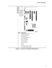
Product Description Item A B C D E F G H I J K L Description Operating system start Hard drive initialization USB initialization Option ROM initialization Video initialization Memory initialization CPU initialization Hard drive activity VR Hot CPU Hot Watch Dog Fire/Back to BIOS +5 V standby power indicator Figure 7. Locations of Onboard LED Indicators 37
Product Description Item A B C D E F G H I J K L Description Operating system start Hard drive initialization USB initialization Option ROM initialization Video initialization Memory initialization CPU initialization Hard drive activity VR Hot CPU Hot Watch Dog Fire/Back to BIOS +5 V standby power indicator Figure 7. Locations of Onboard LED Indicators 37
Product Specification
Page 39
...All installed system memory can be used when there is not possible to use all of system addresses. 39 These functions include the following: • BIOS/SPI Flash device (16 Mbit) • Local APIC (19 MB) • Direct Media Interface (40 MB) • Front side bus interrupts ...(total system memory). Typically the address space that is allocated for Conventional PCI and PCI Express add-in cards, PCI Express configuration space, BIOS (SPI Flash device), and chipset overhead resides above the 4 GB boundary. The board remaps physical memory from the top of addressable system ...
...All installed system memory can be used when there is not possible to use all of system addresses. 39 These functions include the following: • BIOS/SPI Flash device (16 Mbit) • Local APIC (19 MB) • Direct Media Interface (40 MB) • Front side bus interrupts ...(total system memory). Typically the address space that is allocated for Conventional PCI and PCI Express add-in cards, PCI Express configuration space, BIOS (SPI Flash device), and chipset overhead resides above the 4 GB boundary. The board remaps physical memory from the top of addressable system ...
Product Specification
Page 41
...9FBFF 00000 - 7FFFF Size 16382 MB 64 KB 64 KB 96 KB 160 KB 1 KB 127 KB 512 KB Description Extended memory Runtime BIOS Reserved Potential available high DOS memory (open to the board. Furthermore, improper connection of USB or 1394 header single wire connectors may eventually overload...side I/O connectors and headers (see page 43) 41 Technical Reference 2.1.2 Memory Map Table 10 lists the system memory map. Video memory and BIOS Extended BIOS data (movable by the external devices could cause damage to devices inside the computer's chassis, such as IEEE 1394a. The connectors can be ...
...9FBFF 00000 - 7FFFF Size 16382 MB 64 KB 64 KB 96 KB 160 KB 1 KB 127 KB 512 KB Description Extended memory Runtime BIOS Reserved Potential available high DOS memory (open to the board. Furthermore, improper connection of USB or 1394 header single wire connectors may eventually overload...side I/O connectors and headers (see page 43) 41 Technical Reference 2.1.2 Memory Map Table 10 lists the system memory map. Video memory and BIOS Extended BIOS data (movable by the external devices could cause damage to devices inside the computer's chassis, such as IEEE 1394a. The connectors can be ...
Product Specification
Page 42
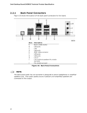
... The back panel audio line out connector is designed to BIOS button USB ports LAN USB ports IEEE 1394a connector USB ports USB ports Line in Line out/front speakers Mic in/side surround Mic in/side surround Figure 10. Intel Desktop Board DX58OG Technical Product Specification 2.2.1 Back Panel Connectors Figure 10 shows...
... The back panel audio line out connector is designed to BIOS button USB ports LAN USB ports IEEE 1394a connector USB ports USB ports Line in Line out/front speakers Mic in/side surround Mic in/side surround Figure 10. Intel Desktop Board DX58OG Technical Product Specification 2.2.1 Back Panel Connectors Figure 10 shows...

Product Specification
Page 53
... Figure 14. Always turn off the power and unplug the power cord from the computer before changing a jumper setting. The 3-pin jumper block determines the BIOS Setup program's mode. Table 25 describes the jumper settings for the three modes: normal, configure, and recovery. Otherwise, the board could be damaged. When the... jumper is set to configure mode and the computer is powered-up, the BIOS compares the processor version and the microcode version in the BIOS and reports if the two match.
... Figure 14. Always turn off the power and unplug the power cord from the computer before changing a jumper setting. The 3-pin jumper block determines the BIOS Setup program's mode. Table 25 describes the jumper settings for the three modes: normal, configure, and recovery. Otherwise, the board could be damaged. When the... jumper is set to configure mode and the computer is powered-up, the BIOS compares the processor version and the microcode version in the BIOS and reports if the two match.


