
Technical Product Specification
Page 34
... o Temperature o Voltage o Fan speed o Processor status o Power supplies ƒ IPMB communication interface ƒ Checks and forces automatic update of firmware of the platform. The following is a list of the major functions of the CMM: ƒ System power control o Storage controllers o Ethernet ...connector for local/remote management access ƒ External Ethernet connector for local/remote management 3.6 Ethernet Switch Module 3.6.1 Introduction The Intel® Ethernet Switch Module (ESM) provides Ethernet connectivity for the CMM to the compute modules and for more details on ....
... o Temperature o Voltage o Fan speed o Processor status o Power supplies ƒ IPMB communication interface ƒ Checks and forces automatic update of firmware of the platform. The following is a list of the major functions of the CMM: ƒ System power control o Storage controllers o Ethernet ...connector for local/remote management access ƒ External Ethernet connector for local/remote management 3.6 Ethernet Switch Module 3.6.1 Introduction The Intel® Ethernet Switch Module (ESM) provides Ethernet connectivity for the CMM to the compute modules and for more details on ....

Technical Product Specification
Page 38
...²C to expander-1) is managed by one for each SCM. the second expander is intended for each expander. Revision 1.7 31 Intel order number E15155-010 The SCM(s) can be downloaded from the expanders, which are connected through SES and exported to all disk drive... expander-2 provides connectivity to a single LED. One overall RAID status LED is managed by the second SCM (if installed). Expander firmware can retrieve hardware monitor and drive backplane IDROM information from the SCM. 3.7.4.2 Interposer Card Functionality SAS expander-1 provides connectivity to the ...
...²C to expander-1) is managed by one for each SCM. the second expander is intended for each expander. Revision 1.7 31 Intel order number E15155-010 The SCM(s) can be downloaded from the expanders, which are connected through SES and exported to all disk drive... expander-2 provides connectivity to a single LED. One overall RAID status LED is managed by the second SCM (if installed). Expander firmware can retrieve hardware monitor and drive backplane IDROM information from the SCM. 3.7.4.2 Interposer Card Functionality SAS expander-1 provides connectivity to the ...

Technical Product Specification
Page 52
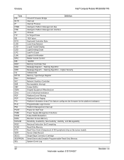
Intel® Modular Server System TPS Glossary Glossary This appendix contains important terms used in the preceding sections. Acronyms are followed by non-acronyms. Word/Acronym ... Port External Product Specification Electrostatic Discharge Ethernet Switch Module Federal Communications Commission Field-Programmable Gate Array Fault Resilient Booting Field Replaceable Unit Front Side Bus Firmware Hub Gigabit Ethernet Ground Graphical User Interface Hard Disk Drive Hub-Link Hot-Swap Controller Input/Output Inter-Integrated Circuit Intelligent Chassis Management Bus Integrated...
Intel® Modular Server System TPS Glossary Glossary This appendix contains important terms used in the preceding sections. Acronyms are followed by non-acronyms. Word/Acronym ... Port External Product Specification Electrostatic Discharge Ethernet Switch Module Federal Communications Commission Field-Programmable Gate Array Fault Resilient Booting Field Replaceable Unit Front Side Bus Firmware Hub Gigabit Ethernet Ground Graphical User Interface Hard Disk Drive Hub-Link Hot-Swap Controller Input/Output Inter-Integrated Circuit Intelligent Chassis Management Bus Integrated...

Technical Product Specification
Page 33
...reset desired settings. 5.1.2 BMC Force Update Procedure When performing a standard BMC firmware update procedure, the update utility places the BMC into the BIOS setup. Open compute module Revision 1.4 27 Intel order number: E15154-007 Disabled (Default) These pins should not be jumpered...passwords are jumpered, the BIOS is forced to boot from previous generation Intel® server boards. Power up and immediately power down time. Remove compute module from modular server chassis. 3. BMC Firmware Force Update Mode - Remove compute module from modular server chassis 3....
...reset desired settings. 5.1.2 BMC Force Update Procedure When performing a standard BMC firmware update procedure, the update utility places the BMC into the BIOS setup. Open compute module Revision 1.4 27 Intel order number: E15154-007 Disabled (Default) These pins should not be jumpered...passwords are jumpered, the BIOS is forced to boot from previous generation Intel® server boards. Power up and immediately power down time. Remove compute module from modular server chassis. 3. BMC Firmware Force Update Mode - Remove compute module from modular server chassis 3....

Technical Product Specification
Page 34
..., and the power button functionality of the control panel is present, the Integrated BMC controller on the server. 28 Revision 1.4 Intel order number: E15154-007 Power down and remove AC power 9. disabled position when the server is restored. Move jumper from Default...position (pins 2-3) to "Disabled" position (pins 2-3) 11. Reinstall the compute module into the modular server chassis 13. 4BJumper Block Settings Intel® Compute Module MFS5000SI TPS 4. Move jumper from "Enabled" position (pins 1-2) to "Enabled" position (pins 1-2) 5. This jumper should only...
..., and the power button functionality of the control panel is present, the Integrated BMC controller on the server. 28 Revision 1.4 Intel order number: E15154-007 Power down and remove AC power 9. disabled position when the server is restored. Move jumper from Default...position (pins 2-3) to "Disabled" position (pins 2-3) 11. Reinstall the compute module into the modular server chassis 13. 4BJumper Block Settings Intel® Compute Module MFS5000SI TPS 4. Move jumper from "Enabled" position (pins 1-2) to "Enabled" position (pins 1-2) 5. This jumper should only...

Technical Product Specification
Page 36
...is not supported on this server board. ƒ Non-ECC memory is not validated and is supported. Previous generation Intel® Xeon® processors are not supported. ƒ For best performance, the number of identical revision, core voltage...in cards, and peripherals for this position and should be populated to its default position (pins 2-3). 30 Revision 1.4 Intel order number: E15154-007 CPU 1 is located near the edge of the server board and must be greater than...enabled" position (pins 1-2). The server should never be used when the standard firmware update process fails.
...is not supported on this server board. ƒ Non-ECC memory is not validated and is supported. Previous generation Intel® Xeon® processors are not supported. ƒ For best performance, the number of identical revision, core voltage...in cards, and peripherals for this position and should be populated to its default position (pins 2-3). 30 Revision 1.4 Intel order number: E15154-007 CPU 1 is located near the edge of the server board and must be greater than...enabled" position (pins 1-2). The server should never be used when the standard firmware update process fails.
Technical Product Specification
Page 48
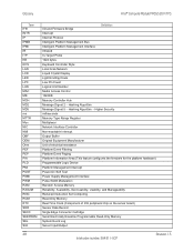
... Equipment Manufacturer Unit of electrical resistance Platform Event Filtering Platform Event Paging Platform Information Area (This feature configures the firmware for the platform hardware) Programmable Logic Device Platform Management Interrupt Power-On Self Test Power Supply Management Interface Pulse-...Single Edge Connector Cartridge Serial Electrically Erasable Programmable Read-Only Memory System Event Log 42 Revision 1.4 Intel order number: E15154-007 Hashing Algorithm - Glossary Intel® Compute Module MFS5000SI TPS Term IFB INTR IP IPMB IPMI IR ITP KB KCS LAN ...
... Equipment Manufacturer Unit of electrical resistance Platform Event Filtering Platform Event Paging Platform Information Area (This feature configures the firmware for the platform hardware) Programmable Logic Device Platform Management Interrupt Power-On Self Test Power Supply Management Interface Pulse-...Single Edge Connector Cartridge Serial Electrically Erasable Programmable Read-Only Memory System Event Log 42 Revision 1.4 Intel order number: E15154-007 Hashing Algorithm - Glossary Intel® Compute Module MFS5000SI TPS Term IFB INTR IP IPMB IPMI IR ITP KB KCS LAN ...

Technical Product Specification
Page 24
... bridge, and interfaces with support for I2C devices ƒ Low Pin Count (LPC) interface support ƒ Firmware Hub (FWH) interface support ƒ Serial Peripheral Interface (SPI) support Revision 1.5 17 Intel order number: E64311-007 The Intel® 5520 Chipset IOH is capable of interfacing with additional support for up to the legacy bridge...
... bridge, and interfaces with support for I2C devices ƒ Low Pin Count (LPC) interface support ƒ Firmware Hub (FWH) interface support ƒ Serial Peripheral Interface (SPI) support Revision 1.5 17 Intel order number: E64311-007 The Intel® 5520 Chipset IOH is capable of interfacing with additional support for up to the legacy bridge...

Technical Product Specification
Page 26
Firmware usage of these hardware features is required for IPMI-based server management. Intel® Compute Module MFS5520VI TPS Functional Architecture ƒ Four external connectors are located on the front of the compute module. ƒ One internal... features: ƒ USB 2.0 for keyboard, mouse, and storage devices ƒ Hardware Video Compression for text and graphics ƒ Hardware encryption Revision 1.5 19 Intel order number: E64311-007 The following is a summary of the integrated BMC management hardware features found in the ServerEngines* LLC Pilot II Integrated BMC: ƒ...
Firmware usage of these hardware features is required for IPMI-based server management. Intel® Compute Module MFS5520VI TPS Functional Architecture ƒ Four external connectors are located on the front of the compute module. ƒ One internal... features: ƒ USB 2.0 for keyboard, mouse, and storage devices ƒ Hardware Video Compression for text and graphics ƒ Hardware encryption Revision 1.5 19 Intel order number: E64311-007 The following is a summary of the integrated BMC management hardware features found in the ServerEngines* LLC Pilot II Integrated BMC: ƒ...

Technical Product Specification
Page 39
...Move jumper back to the Clear position (pins 2-3). 5. Remove the compute module from the modular server chassis. 3. Disabled (Default) BMC Firmware Force Update Mode - Close the compute module. 8. In the unlikely event that the desired operation can be jumpered for normal operation These pins...not be achieved with minimal system downtime. Power down the compute module. 2. Open the compute module. 32 Revision 1.5 Intel order number: E64311-007 BMC Firmware Force Update Mode - These pins should have a jumper in place for normal operation. (Default) If these pins are ...
...Move jumper back to the Clear position (pins 2-3). 5. Remove the compute module from the modular server chassis. 3. Disabled (Default) BMC Firmware Force Update Mode - Close the compute module. 8. In the unlikely event that the desired operation can be jumpered for normal operation These pins...not be achieved with minimal system downtime. Power down the compute module. 2. Open the compute module. 32 Revision 1.5 Intel order number: E64311-007 BMC Firmware Force Update Mode - These pins should have a jumper in place for normal operation. (Default) If these pins are ...

Technical Product Specification
Page 40
...; Compute Module MFS5520VI TPS Jumper Block Settings 4. This jumper should never be used when the standard firmware update process fails. Revision 1.5 33 Intel order number: E64311-007 Perform Integrated BMC firmware update procedure. 8. Close the compute module. 12. disabled position when the server is running normally. 5.1.3 Integrated BMC Initialization When the DC power...
...; Compute Module MFS5520VI TPS Jumper Block Settings 4. This jumper should never be used when the standard firmware update process fails. Revision 1.5 33 Intel order number: E64311-007 Perform Integrated BMC firmware update procedure. 8. Close the compute module. 12. disabled position when the server is running normally. 5.1.3 Integrated BMC Initialization When the DC power...

Technical Product Specification
Page 42
... compute module is not supported in this position and should never be run with TDP higher than one processor cannot be used when the standard firmware update process fails. A six-DIMM configuration (DIMM sockets A1, B1, C1, D1, E1, and F1) performs better than a one-DIMM ...and is running normally. ƒ When performing the BIOS update procedure, the BIOS select jumper must be set to its default position (pins 1-2). Intel® Compute Module MFS5520VI TPS Appendix A: Integration and Usage Tips Appendix A: Integration and Usage Tips ƒ When two processors are installed, both...
... compute module is not supported in this position and should never be run with TDP higher than one processor cannot be used when the standard firmware update process fails. A six-DIMM configuration (DIMM sockets A1, B1, C1, D1, E1, and F1) performs better than a one-DIMM ...and is running normally. ƒ When performing the BIOS update procedure, the BIOS select jumper must be set to its default position (pins 1-2). Intel® Compute Module MFS5520VI TPS Appendix A: Integration and Usage Tips Appendix A: Integration and Usage Tips ƒ When two processors are installed, both...

Technical Product Specification
Page 49
... encountered a stuck key error. PCI component encountered a PERR error. Processor and chipset stepping configuration is resolved. Appendix C: POST Error Messages and Handling Intel® Compute Module MFS5520VI TPS Appendix C: POST Error Messages and Handling Whenever possible, the BIOS outputs the current boot progress codes on the Error Manager...The setup POST error Pause setting determines whether the system pauses to replace the erroneous unit. The user needs to reflash the firmware. The setup POST error Pause setting does not have any effect with this error. The SAS RAID...
... encountered a stuck key error. PCI component encountered a PERR error. Processor and chipset stepping configuration is resolved. Appendix C: POST Error Messages and Handling Intel® Compute Module MFS5520VI TPS Appendix C: POST Error Messages and Handling Whenever possible, the BIOS outputs the current boot progress codes on the Error Manager...The setup POST error Pause setting determines whether the system pauses to replace the erroneous unit. The user needs to reflash the firmware. The setup POST error Pause setting does not have any effect with this error. The SAS RAID...
Technical Product Specification
Page 55
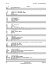
...Interrupt Output Buffer Original Equipment Manufacturer Unit of electrical resistance Platform Event Filtering Platform Event Paging Platform Information Area (This feature configures the firmware for the platform hardware) Programmable Logic Device Platform Management Interrupt Power-On Self Test Power Supply Management Interface Pulse-Width Modulation Random ...Data Record Single Edge Connector Cartridge Serial Electrically Erasable Programmable Read-Only Memory System Event Log Server Input/Output 48 Revision 1.5 Intel order number: E64311-007 Hashing Algorithm -
...Interrupt Output Buffer Original Equipment Manufacturer Unit of electrical resistance Platform Event Filtering Platform Event Paging Platform Information Area (This feature configures the firmware for the platform hardware) Programmable Logic Device Platform Management Interrupt Power-On Self Test Power Supply Management Interface Pulse-Width Modulation Random ...Data Record Single Edge Connector Cartridge Serial Electrically Erasable Programmable Read-Only Memory System Event Log Server Input/Output 48 Revision 1.5 Intel order number: E64311-007 Hashing Algorithm -

Technical Product Specification
Page 47
...Move jumper from the emergency BIOS c image. Disabled (Default) U p2-3 d a ME Firmware Force Update Mode - Remove the compute module from previous generation Intel® server boards. These pins should not be jumpered for normal operation J1F9: Password 1-2 ...up the compute module. 40 Revision 1.0 Intel order number: G51989-002 Recovery Jumpers Jumper Name J1F3: BMC Force Update Pins 1-2 What happens at system reset ... Disabled (Default) 2-3 BMC Firmware Force Update Mode - o v e r 1-2 ME Firmware Force Update Mode - The following procedure ...
...Move jumper from the emergency BIOS c image. Disabled (Default) U p2-3 d a ME Firmware Force Update Mode - Remove the compute module from previous generation Intel® server boards. These pins should not be jumpered for normal operation J1F9: Password 1-2 ...up the compute module. 40 Revision 1.0 Intel order number: G51989-002 Recovery Jumpers Jumper Name J1F3: BMC Force Update Pins 1-2 What happens at system reset ... Disabled (Default) 2-3 BMC Firmware Force Update Mode - o v e r 1-2 ME Firmware Force Update Mode - The following procedure ...

Technical Product Specification
Page 48
... remain in the event the standard ME firmware update process fails. Open the compute module. 4. Close the compute module. 12. Power up the compute module. 7. The following procedure should be completed in the default - Revision 1.0 41 Intel order number: G51989-002 Remove the compute...position. During this position and should never be run with the force BMC update jumper set in the event the standard Integrated BMC firmware update process fails. 1. Note: Normal Integrated BMC functionality (for example, KVM, monitoring, and remote media) is disabled with the...
... remain in the event the standard ME firmware update process fails. Open the compute module. 4. Close the compute module. 12. Power up the compute module. 7. The following procedure should be completed in the default - Revision 1.0 41 Intel order number: G51989-002 Remove the compute...position. During this position and should never be run with the force BMC update jumper set in the event the standard Integrated BMC firmware update process fails. 1. Note: Normal Integrated BMC functionality (for example, KVM, monitoring, and remote media) is disabled with the...

Technical Product Specification
Page 49
... the compute module enclosure. 9. Close the compute module enclosure. 11. Perform the ME firmware update procedure as documented in the README.TXT file that is included in the given ME firmware update package (same package as user binary or language blocks. When the flash update completes...enclosure 3. Move the BIOS recovery jumper to its original position. 4. The user should now boot using the updated system BIOS. 42 Revision 1.0 Intel order number: G51989-002 Insert a bootable BIOS recovery media containing the new BIOS image files. 4. Reinsert the compute module and power up ....
... the compute module enclosure. 9. Close the compute module enclosure. 11. Perform the ME firmware update procedure as documented in the README.TXT file that is included in the given ME firmware update package (same package as user binary or language blocks. When the flash update completes...enclosure 3. Move the BIOS recovery jumper to its original position. 4. The user should now boot using the updated system BIOS. 42 Revision 1.0 Intel order number: G51989-002 Insert a bootable BIOS recovery media containing the new BIOS image files. 4. Reinsert the compute module and power up ....

Technical Product Specification
Page 51
...supported as long as they are not supported. Processors must be installed in this position and should only be used when the standard firmware update process fails. However, the stepping of one processor cannot be set to and including 95 Watts. CPU 1 must be populated for ...example, KVM, monitoring, and remote media) is disabled with a Thermal Design Power (TDP) of up to its default position (pins 1-2). 44 Revision 1.0 Intel order number: G51989-002 For example, a two-DIMM configuration performs better than a four-DIMM configuration (DIMM sockets A1, B1, C1, and D1). ...
...supported as long as they are not supported. Processors must be installed in this position and should only be used when the standard firmware update process fails. However, the stepping of one processor cannot be set to and including 95 Watts. CPU 1 must be populated for ...example, KVM, monitoring, and remote media) is disabled with a Thermal Design Power (TDP) of up to its default position (pins 1-2). 44 Revision 1.0 Intel order number: G51989-002 For example, a two-DIMM configuration performs better than a four-DIMM configuration (DIMM sockets A1, B1, C1, and D1). ...
Technical Product Specification
Page 65
...Equipment Manufacturer Unit of electrical resistance Platform Event Filtering Platform Event Paging Platform Information Area (This feature configures the firmware for the platform hardware) Programmable Logic Device Platform Management Interrupt Power-On Self Test Power Supply Management Interface ... Erasable Programmable Read-Only Memory System Event Log Server Input/Output 58 Intel Confidential Revision 1.0 Intel order number: G51989-002 Hashing Algorithm - Hashing Algorithm Message Digest 5 - Glossary Intel® Compute Module MFS2600KI TPS Term IFB INTR IP IPMB IPMI IR...
...Equipment Manufacturer Unit of electrical resistance Platform Event Filtering Platform Event Paging Platform Information Area (This feature configures the firmware for the platform hardware) Programmable Logic Device Platform Management Interrupt Power-On Self Test Power Supply Management Interface ... Erasable Programmable Read-Only Memory System Event Log Server Input/Output 58 Intel Confidential Revision 1.0 Intel order number: G51989-002 Hashing Algorithm - Hashing Algorithm Message Digest 5 - Glossary Intel® Compute Module MFS2600KI TPS Term IFB INTR IP IPMB IPMI IR...

Specification Update
Page 7
... good FC packets in Windows* Server 2008 R2 with MFS5000SI. .. 34 51. Revertible hot spare does not return to the default time interval after system firmware is wrong when mirroring mode on Oct 27 2009 30 42. The rKVM will disable CPU2 35 54. Select rKVM help instead of "Received Pause...
... good FC packets in Windows* Server 2008 R2 with MFS5000SI. .. 34 51. Revertible hot spare does not return to the default time interval after system firmware is wrong when mirroring mode on Oct 27 2009 30 42. The rKVM will disable CPU2 35 54. Select rKVM help instead of "Received Pause...