
Technical Product Specification
Page 2
...use of these for future definition and shall have no liability whatsoever, and Intel disclaims any express or implied warranty, relating to sale and/or use Intel developed server building blocks to consult vendor datasheets and operating parameters to specifications and product ...rights is provided in medical, life saving, or life sustaining applications. Added MFSYS25V2 info. Copyright © Intel Corporation 2007-2011 ii Revision 1.7 Intel order number E15155-010 Except as provided in Intel's Terms and Conditions of others. Updated Power Budget of any time, without...
...use of these for future definition and shall have no liability whatsoever, and Intel disclaims any express or implied warranty, relating to sale and/or use Intel developed server building blocks to consult vendor datasheets and operating parameters to specifications and product ...rights is provided in medical, life saving, or life sustaining applications. Added MFSYS25V2 info. Copyright © Intel Corporation 2007-2011 ii Revision 1.7 Intel order number E15155-010 Except as provided in Intel's Terms and Conditions of others. Updated Power Budget of any time, without...

Technical Product Specification
Page 3
... Board...10 2.4.2 Storage Interposer Board 11 2.5 Mounting and Service Features 11 2.5.1 Chassis ...11 2.5.2 Rails...11 2.6 Server Management 11 2.6.1 Chassis Management Module 12 2.6.2 Compute Module Management 12 2.7 Reliability, Availability, Serviceability, Usability, Manageability (RASUM... Management Module 22 3.5.1 Introduction ...22 3.5.2 Mechanical Outline 24 3.5.3 Block Diagram ...25 Revision 1.7 iii Intel order number E15155-010 Intel® Modular Server System TPS Table of Contents Table of Contents 1. Rear 7 2.3.1 Power Supply Module 7 2.3.2 I...
... Board...10 2.4.2 Storage Interposer Board 11 2.5 Mounting and Service Features 11 2.5.1 Chassis ...11 2.5.2 Rails...11 2.6 Server Management 11 2.6.1 Chassis Management Module 12 2.6.2 Compute Module Management 12 2.7 Reliability, Availability, Serviceability, Usability, Manageability (RASUM... Management Module 22 3.5.1 Introduction ...22 3.5.2 Mechanical Outline 24 3.5.3 Block Diagram ...25 Revision 1.7 iii Intel order number E15155-010 Intel® Modular Server System TPS Table of Contents Table of Contents 1. Rear 7 2.3.1 Power Supply Module 7 2.3.2 I...

Technical Product Specification
Page 4
... VCCI (Japan) ...43 4.4.5 BSMI (Taiwan) ...43 Glossary...45 Reference Documents ...48 iv Revision 1.7 Intel order number E15155-010 Product Regulatory Requirements 34 4.1 Product Regulatory Compliance 34 4.1.1 Product Safety Compliance 34 ... Electromagnetic Compatibility Notices 41 4.4.1 FCC Verification Statement (USA 41 4.4.2 ICES-003 (Canada 42 4.4.3 Europe (CE Declaration of Contents Intel® Modular Server System TPS 3.5.4 Drawings...26 3.5.5 Architectural Overview 26 3.6 Ethernet Switch Module 27 3.6.1 Introduction ...27 3.6.2 Mechanical Outline 28 3.6.3 ...
... VCCI (Japan) ...43 4.4.5 BSMI (Taiwan) ...43 Glossary...45 Reference Documents ...48 iv Revision 1.7 Intel order number E15155-010 Product Regulatory Requirements 34 4.1 Product Regulatory Compliance 34 4.1.1 Product Safety Compliance 34 ... Electromagnetic Compatibility Notices 41 4.4.1 FCC Verification Statement (USA 41 4.4.2 ICES-003 (Canada 42 4.4.3 Europe (CE Declaration of Contents Intel® Modular Server System TPS 3.5.4 Drawings...26 3.5.5 Architectural Overview 26 3.6 Ethernet Switch Module 27 3.6.1 Introduction ...27 3.6.2 Mechanical Outline 28 3.6.3 ...
Technical Product Specification
Page 5
.... Front View of Storage Controller Module Board 30 Figure 23. Midplane Board Mechanical Outline (Front View 19 Figure 13. Mechanical Outline of Server Platform 5 Figure 4. Front View of Intel® Modular Server System MFSYS25 System Board Connectivity 9 Figure 6. Chassis Management Module Board Outline (Top View 24 Figure 17. Ethernet Switch Module Block Diagram...
.... Front View of Storage Controller Module Board 30 Figure 23. Midplane Board Mechanical Outline (Front View 19 Figure 13. Mechanical Outline of Server Platform 5 Figure 4. Front View of Intel® Modular Server System MFSYS25 System Board Connectivity 9 Figure 6. Chassis Management Module Board Outline (Top View 24 Figure 17. Ethernet Switch Module Block Diagram...

Technical Product Specification
Page 6
Server Platform Feature List 2 Table 2. Environmental Specifications Summary 14 Table 3. Power Budget of Chassis 15 vi Revision 1.7 Intel order number E15155-010 Power and Heat Dissipation Specifications of Hardware Components 15 Table 6. List of Tables Intel® Modular Server System TPS List of Hardware Components 15 Table 5. Physical Dimensions of Tables Table 1. Physical Specifications of Chassis 14 Table 4.
Server Platform Feature List 2 Table 2. Environmental Specifications Summary 14 Table 3. Power Budget of Chassis 15 vi Revision 1.7 Intel order number E15155-010 Power and Heat Dissipation Specifications of Hardware Components 15 Table 6. List of Tables Intel® Modular Server System TPS List of Hardware Components 15 Table 5. Physical Dimensions of Tables Table 1. Physical Specifications of Chassis 14 Table 4.

Technical Product Specification
Page 7
Intel® Modular Server System TPS < This page intentionally left blank. > List of Tables Revision 1.7 vii Intel order number E15155-010
Intel® Modular Server System TPS < This page intentionally left blank. > List of Tables Revision 1.7 vii Intel order number E15155-010

Technical Product Specification
Page 8
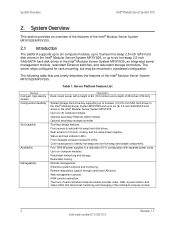
...-swap power, cooling, and hard disk drives. Exceptions will call out either MFSYS25 or MFSYS25V2. Building on previous server platforms, the Intel® Modular Server System MFSYS25/MFSYS35 includes redundant storage and networking, in the document to six dual-processor compute...of 12 Multi-Core Intel® Xeon® 5000 sequence processors. The Intel® Modular Server System MFSYS25/MFSYS35 supports up to MFSYS25 are available: ƒ Intel® Modular Server System MFSYS25 ƒ Intel® Modular Server System MFSYS25V2 ƒ Intel® Modular Server System MFSYS35 Note: ...
...-swap power, cooling, and hard disk drives. Exceptions will call out either MFSYS25 or MFSYS25V2. Building on previous server platforms, the Intel® Modular Server System MFSYS25/MFSYS35 includes redundant storage and networking, in the document to six dual-processor compute...of 12 Multi-Core Intel® Xeon® 5000 sequence processors. The Intel® Modular Server System MFSYS25/MFSYS35 supports up to MFSYS25 are available: ƒ Intel® Modular Server System MFSYS25 ƒ Intel® Modular Server System MFSYS25V2 ƒ Intel® Modular Server System MFSYS35 Note: ...
Technical Product Specification
Page 9
...Table 1. Front access to six compute modules. Tool-less design features. Front viewable compute module ID LEDs. System Overview Intel® Modular Server System TPS 2. Web management console. Redundant cooling. Extensive system sensors and monitoring. KVM console redirection. The front of each... compute module provides video, USB, a power button, and status LEDs that allow local monitoring and managing of the Intel® Modular Server System MFSYS25/MFSYS35. 2.1 Introduction The platform supports up to six compute modules, up to fourteen hot-swap 2.5-inch SAS...
...Table 1. Front access to six compute modules. Tool-less design features. Front viewable compute module ID LEDs. System Overview Intel® Modular Server System TPS 2. Web management console. Redundant cooling. Extensive system sensors and monitoring. KVM console redirection. The front of each... compute module provides video, USB, a power button, and status LEDs that allow local monitoring and managing of the Intel® Modular Server System MFSYS25/MFSYS35. 2.1 Introduction The platform supports up to six compute modules, up to fourteen hot-swap 2.5-inch SAS...
Technical Product Specification
Page 10
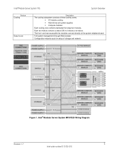
...ƒ Hard drives and power supplies ƒ Compute modules Each cooling zone contains dedicated hot-swap fan modules. Figure 1. Intel® Modular Server System TPS System Overview Feature Cooling Easy to indicate a fan failure. Each fan module contains a status LED to use Description... The cooling subsystem consists of storage and network. Intel® Modular Server System MFSYS25 Wiring Diagram Revision 1.7 3 Intel order number E15155-010 The front- Full system management through Web browser. and rear-accessible fan ...
...ƒ Hard drives and power supplies ƒ Compute modules Each cooling zone contains dedicated hot-swap fan modules. Figure 1. Intel® Modular Server System TPS System Overview Feature Cooling Easy to indicate a fan failure. Each fan module contains a status LED to use Description... The cooling subsystem consists of storage and network. Intel® Modular Server System MFSYS25 Wiring Diagram Revision 1.7 3 Intel order number E15155-010 The front- Full system management through Web browser. and rear-accessible fan ...

Technical Product Specification
Page 12
... Overview B A C D Item A B C D Compute modules (six) Description Storage enclosure: ƒ 14 hot-swap 2.5-inch SAS hard disk drives - Intel® Modular Server System MFSYS25 only ƒ 6 hot-swap 3.5-inch SAS/SATA hard disk drives - Intel® Modular Server System MFSYS35 only I/O cooling module System Fault LED (amber) Figure 3. Front Figure 3 shows the front view of...
... Overview B A C D Item A B C D Compute modules (six) Description Storage enclosure: ƒ 14 hot-swap 2.5-inch SAS hard disk drives - Intel® Modular Server System MFSYS25 only ƒ 6 hot-swap 3.5-inch SAS/SATA hard disk drives - Intel® Modular Server System MFSYS35 only I/O cooling module System Fault LED (amber) Figure 3. Front Figure 3 shows the front view of...
Technical Product Specification
Page 13
...features: ƒ Bays for 14 hot-swap 2.5-inch SAS hard disk drives in the Intel® Modular Server System MFSYS25 and six (6) 3.5-inch SAS/SATA hard drives in the Intel® Modular Server System MFSYS35 ƒ At least one storage controller in an I/O slot Because hard ...12V power from the front of the system even though it cools the I /O modules. System Overview Intel® Modular Server System TPS 2.2.1 Compute Module The Intel® Modular Server System MFSYS25/MFSYS35 supports up to the chassis management module, storage controllers and switch modules through the storage ...
...features: ƒ Bays for 14 hot-swap 2.5-inch SAS hard disk drives in the Intel® Modular Server System MFSYS25 and six (6) 3.5-inch SAS/SATA hard drives in the Intel® Modular Server System MFSYS35 ƒ At least one storage controller in an I/O slot Because hard ...12V power from the front of the system even though it cools the I /O modules. System Overview Intel® Modular Server System TPS 2.2.1 Compute Module The Intel® Modular Server System MFSYS25/MFSYS35 supports up to the chassis management module, storage controllers and switch modules through the storage ...
Technical Product Specification
Page 14
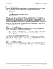
...Description Power supply units (four, 3+1) Main cooling modules (required) Ethernet switch modules Storage controllers Management module (required) AF002564 Figure 4. One Revision 1.7 7 Intel order number E15155-010 Each supply has its own AC input power connector and is rated at 1000 W over an input range of the chassis... following figure shows the rear view of the chassis can accommodate up to two hot-swap Ethernet switch modules. Intel® Modular Server System TPS System Overview 2.3 External Chassis Features - Each power supply includes two fans that provide cooling for a...
...Description Power supply units (four, 3+1) Main cooling modules (required) Ethernet switch modules Storage controllers Management module (required) AF002564 Figure 4. One Revision 1.7 7 Intel order number E15155-010 Each supply has its own AC input power connector and is rated at 1000 W over an input range of the chassis... following figure shows the rear view of the chassis can accommodate up to two hot-swap Ethernet switch modules. Intel® Modular Server System TPS System Overview 2.3 External Chassis Features - Each power supply includes two fans that provide cooling for a...
Technical Product Specification
Page 15
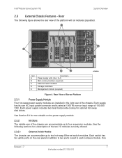
...Chassis Features The following figures provide an internal view of the entire Intel® Modular Server System MFSYS25/MFSYS35. One storage controller is for configuration and management of how the Intel® Modular Server System MFSYS25/MFSYS35 system boards are connected. 8 Revision 1.7 Intel order number E15155-010 Storage controller failures are installed on the ... contains two redundant fans that operate in the middlerear of the chassis amid the four I/O slots, provides an Internet browser interface that allows for Intel® Modular Server System MFSYS25V2 only.
...Chassis Features The following figures provide an internal view of the entire Intel® Modular Server System MFSYS25/MFSYS35. One storage controller is for configuration and management of how the Intel® Modular Server System MFSYS25/MFSYS35 system boards are connected. 8 Revision 1.7 Intel order number E15155-010 Storage controller failures are installed on the ... contains two redundant fans that operate in the middlerear of the chassis amid the four I/O slots, provides an Internet browser interface that allows for Intel® Modular Server System MFSYS25V2 only.
Technical Product Specification
Page 16
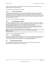
View of Intel® Modular Server System MFSYS25 System Board Connectivity Revision 1.7 9 Intel order number E15155-010 Intel® Modular Server System TPS System Overview Item A B C D E F G H I Server board Description 14-drive backplane Interposer board (connects drive backplane to midplane) I/O fan controller Midplane board Compute module fan controllers Storage controller boards Switch module boards Chassis management module board Figure 5.
View of Intel® Modular Server System MFSYS25 System Board Connectivity Revision 1.7 9 Intel order number E15155-010 Intel® Modular Server System TPS System Overview Item A B C D E F G H I Server board Description 14-drive backplane Interposer board (connects drive backplane to midplane) I/O fan controller Midplane board Compute module fan controllers Storage controller boards Switch module boards Chassis management module board Figure 5.

Technical Product Specification
Page 17
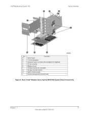
View of Intel® Modular Server System MFSYS35 System Board Connectivity 2.4.1 Midplane Board The midplane board mounts vertically in the middle of the chassis and cannot be a part of ... Storage controller boards Switch module boards Chassis management module board Figure 6. This board is considered to all chassis subassemblies and options. System Overview Intel® Modular Server System TPS Item A B C D E F G H I Server board Description 6-drive backplane Interposer board (connects drive backplane to midplane) I /O signaling, both high-speed and low-speed, to be ...
View of Intel® Modular Server System MFSYS35 System Board Connectivity 2.4.1 Midplane Board The midplane board mounts vertically in the middle of the chassis and cannot be a part of ... Storage controller boards Switch module boards Chassis management module board Figure 6. This board is considered to all chassis subassemblies and options. System Overview Intel® Modular Server System TPS Item A B C D E F G H I Server board Description 6-drive backplane Interposer board (connects drive backplane to midplane) I /O signaling, both high-speed and low-speed, to be ...
Technical Product Specification
Page 18
Intel® Modular Server System TPS System Overview 2.4.2 Storage Interposer Board The interposer board.... No loose hardware is supported by standard EIA rack units, where 1U equals 1.75 inches. The Intel® Modular Server System MFSYS25/MFSYS35 uses fixed rails. The management subsystem conforms to the IPMI v2.0 Specification for external ...with an optional rail kit. The system rests on the front flanges of all modules. SNMP is needed. 2.6 Server Management The management of the system. The chassis can be done through Ethernet) to the rack using a tool-less...
Intel® Modular Server System TPS System Overview 2.4.2 Storage Interposer Board The interposer board.... No loose hardware is supported by standard EIA rack units, where 1U equals 1.75 inches. The Intel® Modular Server System MFSYS25/MFSYS35 uses fixed rails. The management subsystem conforms to the IPMI v2.0 Specification for external ...with an optional rail kit. The system rests on the front flanges of all modules. SNMP is needed. 2.6 Server Management The management of the system. The chassis can be done through Ethernet) to the rack using a tool-less...

Technical Product Specification
Page 19
... Management Each compute module contains an Integrated Baseboard Management Controller (BMC) that runs Linux to control the security of these management features. System Overview Intel® Modular Server System TPS HDD Backplane I2C BUSSES 10/100Mbps Ethernet Clear Bay: Chassis Management Connections I2C BUS 10/100Mbps Ethernet SPI BUS PSU PSU STORAGE...
... Management Each compute module contains an Integrated Baseboard Management Controller (BMC) that runs Linux to control the security of these management features. System Overview Intel® Modular Server System TPS HDD Backplane I2C BUSSES 10/100Mbps Ethernet Clear Bay: Chassis Management Connections I2C BUS 10/100Mbps Ethernet SPI BUS PSU PSU STORAGE...
Technical Product Specification
Page 20
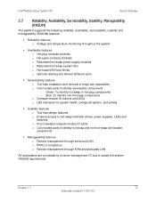
Green: To identify hot-swap or hot-plug components - Revision 1.7 13 Intel order number E15155-010 Blue: To identify non-hot-swap components o Compute module ID buttons and LEDs o LED indicators ... through serial and LAN o IPMI 2.0 compliance o Remote management through KVM and dedicated LAN All subsystems are connected by a server management I2C bus to identify serviceable components - Intel® Modular Server System TPS System Overview 2.7 Reliability, Availability, Serviceability, Usability, Manageability (RASUM) The platform supports the following reliability, availability, ...
Green: To identify hot-swap or hot-plug components - Revision 1.7 13 Intel order number E15155-010 Blue: To identify non-hot-swap components o Compute module ID buttons and LEDs o LED indicators ... through serial and LAN o IPMI 2.0 compliance o Remote management through KVM and dedicated LAN All subsystems are connected by a server management I2C bus to identify serviceable components - Intel® Modular Server System TPS System Overview 2.7 Reliability, Availability, Serviceability, Usability, Manageability (RASUM) The platform supports the following reliability, availability, ...

Technical Product Specification
Page 21
...MsanPiN 001-96 3.1.2 Physical Specifications Summary The following table describes the physical specifications of the Intel® Modular Server System MFSYS25/MFSYS35 and all components. 14 Revision 1.7 Intel order number E15155-010 System Details 3.1 Specifications 3.1.1 Environmental Specifications Summary The following table describes ... pulse, 100 pulses in each direction, on each of the three axes Trapezoidal, 25 G, two drops on each of the Intel® Modular Server System MFSYS25/MFSYS35 Table 2. tested to CISPR 22 Class A, EN 55022 Class A and 89/336/EEC, VCCI Class A, ...
...MsanPiN 001-96 3.1.2 Physical Specifications Summary The following table describes the physical specifications of the Intel® Modular Server System MFSYS25/MFSYS35 and all components. 14 Revision 1.7 Intel order number E15155-010 System Details 3.1 Specifications 3.1.1 Environmental Specifications Summary The following table describes ... pulse, 100 pulses in each direction, on each of the three axes Trapezoidal, 25 G, two drops on each of the Intel® Modular Server System MFSYS25/MFSYS35 Table 2. tested to CISPR 22 Class A, EN 55022 Class A and 89/336/EEC, VCCI Class A, ...
Technical Product Specification
Page 22
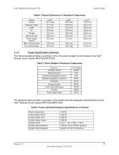
...416.9 mm 3.1.3 Power Specifications Summary The following table provides a summary of the 12V power budget for the Intel® Modular Server System MFSYS25/MFSYS35. Table 6. Physical Dimensions of Hardware Components Module Chassis Compute module CMM I/O Storage Hard drive...W 188 W 26 W The following table provides a summary of the power and heat dissipation specifications for all modules in the Intel® Modular Server System MFSYS25/MFSYS35. Table 5. Power and Heat Dissipation Specifications of Chassis Power Supply Input Power Supply Output System Power Input System ...
...416.9 mm 3.1.3 Power Specifications Summary The following table provides a summary of the 12V power budget for the Intel® Modular Server System MFSYS25/MFSYS35. Table 6. Physical Dimensions of Hardware Components Module Chassis Compute module CMM I/O Storage Hard drive...W 188 W 26 W The following table provides a summary of the power and heat dissipation specifications for all modules in the Intel® Modular Server System MFSYS25/MFSYS35. Table 5. Power and Heat Dissipation Specifications of Chassis Power Supply Input Power Supply Output System Power Input System ...