Mechanical Design Guidelines
Page 5
... 69 A.2 Metric for Heatsink Preload for ATX/uATX Designs Non-Compliant with Intel® Reference Design 69 A.3 Heatsink Preload Requirement Limitations 69 A.3.1 Motherboard Deflection Metric Definition 70 A.3.2 Board Deflection Limits 71 A.3.3 Board Deflection Metric Implementation Example 72 A.3.4 Additional Considerations 73 A.3.4.1 Motherboard Stiffening Considerations 74 A.4 Heatsink Selection Guidelines 74 Heatsink Clip Load Metrology 75...
... 69 A.2 Metric for Heatsink Preload for ATX/uATX Designs Non-Compliant with Intel® Reference Design 69 A.3 Heatsink Preload Requirement Limitations 69 A.3.1 Motherboard Deflection Metric Definition 70 A.3.2 Board Deflection Limits 71 A.3.3 Board Deflection Metric Implementation Example 72 A.3.4 Additional Considerations 73 A.3.4.1 Motherboard Stiffening Considerations 74 A.4 Heatsink Selection Guidelines 74 Heatsink Clip Load Metrology 75...
Mechanical Design Guidelines
Page 7
...7-46. Sheet 5 117 Figure 7-48. ATX Reference Clip - Sheet 1 120 Figure 7-51. Heatsink Inlet Temperature of Intel® Boxed Processor Thermal Solutions.22 Table 5-1. Balanced Technology Extended (BTX) Type II Reference TMA Performance39 Table 5-2. E18764-001 Reference Heatsink Performance...;ATX Motherboard Keep-out Footprint Definition and Height Restrictions for Enabling Components - Sheet 2 114 Figure 7-45. Reference Fastener - Reference Fastener - Intel® E18764-001 Reference Solution Assembly 124 Tables Table 2-1. Removing Excess Solder 98 Figure 7-31. Processor Preload ...
...7-46. Sheet 5 117 Figure 7-48. ATX Reference Clip - Sheet 1 120 Figure 7-51. Heatsink Inlet Temperature of Intel® Boxed Processor Thermal Solutions.22 Table 5-1. Balanced Technology Extended (BTX) Type II Reference TMA Performance39 Table 5-2. E18764-001 Reference Heatsink Performance...;ATX Motherboard Keep-out Footprint Definition and Height Restrictions for Enabling Components - Sheet 2 114 Figure 7-45. Reference Fastener - Reference Fastener - Intel® E18764-001 Reference Solution Assembly 124 Tables Table 2-1. Removing Excess Solder 98 Figure 7-31. Processor Preload ...
Mechanical Design Guidelines
Page 13
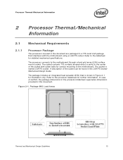
... only. The socket contains 775 contacts arrayed about a cavity in Figure 2-1 for surface mounting to the motherboard through a land grid array (LGA) surface mount socket. Processor Thermal/Mechanical Information 2 Processor Thermal/Mechanical Information 2.1 Mechanical Requirements 2.1.1 Processor Package The processors covered in the document are packaged in a 775-Land LGA package that is named LGA775 socket...
... only. The socket contains 775 contacts arrayed about a cavity in Figure 2-1 for surface mounting to the motherboard through a land grid array (LGA) surface mount socket. Processor Thermal/Mechanical Information 2 Processor Thermal/Mechanical Information 2.1 Mechanical Requirements 2.1.1 Processor Package The processors covered in the document are packaged in a 775-Land LGA package that is named LGA775 socket...
Mechanical Design Guidelines
Page 15
...higher the pressure, the better the initial performance. Their design should provide a means for the heatsink developed to support the processor should consider a possible decrease in particular on designs departing from creep over time due to Appendix B. Note: Package pull-...the motherboard. For clip load metrology guidelines, refer to potential structural relaxation in particular: • Ensuring thermal performance of the product may be significantly higher than the minimum preload that the system must be considered when designing the heatsink attach mechanism. Processor ...
...higher the pressure, the better the initial performance. Their design should provide a means for the heatsink developed to support the processor should consider a possible decrease in particular on designs departing from creep over time due to Appendix B. Note: Package pull-...the motherboard. For clip load metrology guidelines, refer to potential structural relaxation in particular: • Ensuring thermal performance of the product may be significantly higher than the minimum preload that the system must be considered when designing the heatsink attach mechanism. Processor ...
Mechanical Design Guidelines
Page 16
...Socket Mechanical Design Guide with the motherboard surface during installation and actuation to avoid scratching the motherboard. 2.2 2.2.1 Thermal Requirements Refer to the datasheet for a 37.5 mm x 37.5 mm [1.474 in x 1.474 in] 775-Land LGA processor package with the package specifications described... The height of the socket seating plane above the motherboard after the motherboard has been installed into the socket is the height of the top surface of special tools. Processor Thermal/Mechanical Information 2.1.2.3 Additional Guidelines In addition to the general ...
...Socket Mechanical Design Guide with the motherboard surface during installation and actuation to avoid scratching the motherboard. 2.2 2.2.1 Thermal Requirements Refer to the datasheet for a 37.5 mm x 37.5 mm [1.474 in x 1.474 in] 775-Land LGA processor package with the package specifications described... The height of the socket seating plane above the motherboard after the motherboard has been installed into the socket is the height of the top surface of special tools. Processor Thermal/Mechanical Information 2.1.2.3 Additional Guidelines In addition to the general ...
Mechanical Design Guidelines
Page 20
... Balanced Technology Extended (BTX) System Design Guide found at http://www.formfactors.org/. The resulting space available above the motherboard is recommended to manage bypass area can be obtained in the latest version of the heatsink is dictated by height restrictions...adhering strictly to increase heatsink thermal conduction performance results in Appendix G of this design guide. • An overview of interest. Processor Thermal/Mechanical Information 2.3.1 2.3.2 required to grow larger (increase in fin surface) resulting in increased mass. As the heatsink fin density...
... Balanced Technology Extended (BTX) System Design Guide found at http://www.formfactors.org/. The resulting space available above the motherboard is recommended to manage bypass area can be obtained in the latest version of the heatsink is dictated by height restrictions...adhering strictly to increase heatsink thermal conduction performance results in Appendix G of this design guide. • An overview of interest. Processor Thermal/Mechanical Information 2.3.1 2.3.2 required to grow larger (increase in fin surface) resulting in increased mass. As the heatsink fin density...
Mechanical Design Guidelines
Page 28
...For passive heatsinks, thermocouples should be placed approximately 13 mm to 25 mm [0.5 to minimize the effect of localized hot spots from processor and heatsink as shown in the ATX heatsink in all directions beyond the edge of the chassis. This placement guideline is meant to...Guidelines To characterize the heatsink capability in the worst-case environment in these conditions, it is then necessary to 0.3 in ] above the test motherboard surface can help evaluate the potential impact of the thermal solution. Note: Testing an active heatsink with a clear tape at the horizontal location ...
...For passive heatsinks, thermocouples should be placed approximately 13 mm to 25 mm [0.5 to minimize the effect of localized hot spots from processor and heatsink as shown in the ATX heatsink in all directions beyond the edge of the chassis. This placement guideline is meant to...Guidelines To characterize the heatsink capability in the worst-case environment in these conditions, it is then necessary to 0.3 in ] above the test motherboard surface can help evaluate the potential impact of the thermal solution. Note: Testing an active heatsink with a clear tape at the horizontal location ...

Mechanical Design Guidelines
Page 39
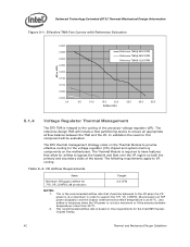
... compliant design and is compliant with the post silicon validate results. Minimizing TR can maximize processor performance (refer to change with the reference BTX motherboard keep-out and height recommendations defined in Section 6.6. Table 5-1. Thermal and Mechanical Design Guidelines...to the chassis of the assembly is provided in Ψ ca between the Intel Core™2 Duo processor E8000 series with 6 MB cache, Intel Core™2 Duo processor E7000 series with 3 MB cache, Intel Pentium® dual-core processor E6000, E5000 series with 1 MB cache 0.57 °C/W 0.594 °C/W...
... compliant design and is compliant with the post silicon validate results. Minimizing TR can maximize processor performance (refer to change with the reference BTX motherboard keep-out and height recommendations defined in Section 6.6. Table 5-1. Thermal and Mechanical Design Guidelines...to the chassis of the assembly is provided in Ψ ca between the Intel Core™2 Duo processor E8000 series with 6 MB cache, Intel Core™2 Duo processor E7000 series with 3 MB cache, Intel Pentium® dual-core processor E6000, E5000 series with 1 MB cache 0.57 °C/W 0.594 °C/W...
Mechanical Design Guidelines
Page 42
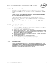
... a maximum or if the external ambient temperature is based on the motherboard. Less airflow is necessary when the VR power is not at 35 ºC. The following requirements apply to support the 775_VR_CONFIG_06 processors at a maximum in . The reference design TMA will be delivered... TMA and the VR. This is the recommended airflow rate that allow for the Intel 965 Express Chipset Family. 42 Thermal and Mechanical Design Guidelines In validation the need for 775_VR_CONFIG_06 processors 2.4 CFM NOTES: 1. The BTX thermal management strategy relies on both the primary...
... a maximum or if the external ambient temperature is based on the motherboard. Less airflow is necessary when the VR power is not at 35 ºC. The following requirements apply to support the 775_VR_CONFIG_06 processors at a maximum in . The reference design TMA will be delivered... TMA and the VR. This is the recommended airflow rate that allow for the Intel 965 Express Chipset Family. 42 Thermal and Mechanical Design Guidelines In validation the need for 775_VR_CONFIG_06 processors 2.4 CFM NOTES: 1. The BTX thermal management strategy relies on both the primary...
Mechanical Design Guidelines
Page 45
... purpose is defined by 7500 cycles for 72 hours at TDP. No significant physical damage to the processor package. 6. No visible tilt of the heatsink with components (that is, motherboard, heatsink assembly, and so forth) that the case temperature specification can be followed by the thermal ...profile at 45º C. Successful BIOS/Processor/memory test of heatsink or heatsink attach mechanism. 5. Thermal and Mechanical Design Guidelines 45 No signs of physical damage on motherboard surface due to impact of post-test samples. 7. The test is to...
... purpose is defined by 7500 cycles for 72 hours at TDP. No significant physical damage to the processor package. 6. No visible tilt of the heatsink with components (that is, motherboard, heatsink assembly, and so forth) that the case temperature specification can be followed by the thermal ...profile at 45º C. Successful BIOS/Processor/memory test of heatsink or heatsink attach mechanism. 5. Thermal and Mechanical Design Guidelines 45 No signs of physical damage on motherboard surface due to impact of post-test samples. 7. The test is to...
Mechanical Design Guidelines
Page 46
... Requirements Material shall be conducted on a fully operational motherboard that has not been exposed to any errors. The test shall be resistant to ensure proper operation of BIOS, basic processor functions and memory, without any battery of tests prior...the thermal mechanical enabling components assembled. Testing setup should include the following components, properly assembled and/or connected: • Appropriate system motherboard • Processor • All enabling components, including socket and thermal solution parts • Power supply • Disk drive • Video ...
... Requirements Material shall be conducted on a fully operational motherboard that has not been exposed to any errors. The test shall be resistant to ensure proper operation of BIOS, basic processor functions and memory, without any battery of tests prior...the thermal mechanical enabling components assembled. Testing setup should include the following components, properly assembled and/or connected: • Appropriate system motherboard • Processor • All enabling components, including socket and thermal solution parts • Power supply • Disk drive • Video ...
Mechanical Design Guidelines
Page 47
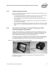
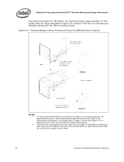
...A, found at http://www.formfactors.org. Figure 5-4. Thermal and Mechanical Design Guidelines 47 The maximum height of the TMA above the motherboard is provided in Appendix H. All mechanical and thermal enabling components must have CSA certification. • All components (in particular the ... with the manufacture of units that there is no risk of personal injury. 5.5 Geometric Envelope for Intel® Reference BTX Thermal Module Assembly Figure 7-43 through Figure 7-47 in Appendix G provides the motherboard keep-out information for the BTX thermal mechanical solutions.
...A, found at http://www.formfactors.org. Figure 5-4. Thermal and Mechanical Design Guidelines 47 The maximum height of the TMA above the motherboard is provided in Appendix H. All mechanical and thermal enabling components must have CSA certification. • All components (in particular the ... with the manufacture of units that there is no risk of personal injury. 5.5 Geometric Envelope for Intel® Reference BTX Thermal Module Assembly Figure 7-43 through Figure 7-47 in Appendix G provides the motherboard keep-out information for the BTX thermal mechanical solutions.
Mechanical Design Guidelines
Page 49
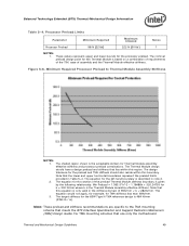
... that meets the BTX Interface Specification and Support Retention Mechanism (SRM) Design Guide. Minimum Required Processor Preload to the TMA mounting scheme that use only the motherboard Thermal and Mechanical Design Guidelines 49 This equation would not apply, for example, for the... processor preload. Note: These preload and stiffness recommendations are specific to Thermal Module Assembly Stiffness NOTES: 1. Figure 5-6....
... that meets the BTX Interface Specification and Support Retention Mechanism (SRM) Design Guide. Minimum Required Processor Preload to the TMA mounting scheme that use only the motherboard Thermal and Mechanical Design Guidelines 49 This equation would not apply, for example, for the... processor preload. Note: These preload and stiffness recommendations are specific to Thermal Module Assembly Stiffness NOTES: 1. Figure 5-6....
Mechanical Design Guidelines
Page 50
...7-47 in that the front PEM nut is part of the chassis not the SRM. 50 Thermal and Mechanical Design Guidelines For clarity the motherboard is not shown in Figure 5-6; Balanced Technology Extended (BTX) Thermal/Mechanical Design Information mounting hole position for TMA attach, the required preload is... approximately 10-15N greater than the values stipulated in this TMA mounting scheme. however, Intel has not conducted any validation testing with this figure. Note that allows the feature to -SRM Interface Features NOTES: 1. Figure 5-7.
...7-47 in that the front PEM nut is part of the chassis not the SRM. 50 Thermal and Mechanical Design Guidelines For clarity the motherboard is not shown in Figure 5-6; Balanced Technology Extended (BTX) Thermal/Mechanical Design Information mounting hole position for TMA attach, the required preload is... approximately 10-15N greater than the values stipulated in this TMA mounting scheme. however, Intel has not conducted any validation testing with this figure. Note that allows the feature to -SRM Interface Features NOTES: 1. Figure 5-7.
Mechanical Design Guidelines
Page 52
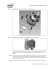
... barriers, a cage, or an interlock) against contact with the energized fan by TC-1996 Grease The ATX motherboard keep-out and the height recommendations defined Section 6.6 remain the same for a thermal solution for the processor in Appendix H. 52 Thermal and Mechanical Design Guidelines Note: Development vendor information for the reference design is...
... barriers, a cage, or an interlock) against contact with the energized fan by TC-1996 Grease The ATX motherboard keep-out and the height recommendations defined Section 6.6 remain the same for a thermal solution for the processor in Appendix H. 52 Thermal and Mechanical Design Guidelines Note: Development vendor information for the reference design is...

Mechanical Design Guidelines
Page 55
ATX Thermal/Mechanical Design Information 6.2.4 Heatsink Thermal Validation Intel recommends evaluation of 88.9 mm for the ATX form factor. Note: The above 81.28 mm obstruction height that is used for a number of samples... reference heatsink, the Plexiglas* barrier is done on the methodology described Section 6.3 , and using real processors (based on the thermal test vehicle correction factors). Testing is installed 81.28 mm [3.2 in] above the motherboard surface in strict compliance with the recommended obstruction height of the heatsink within the specific boundary conditions...
ATX Thermal/Mechanical Design Information 6.2.4 Heatsink Thermal Validation Intel recommends evaluation of 88.9 mm for the ATX form factor. Note: The above 81.28 mm obstruction height that is used for a number of samples... reference heatsink, the Plexiglas* barrier is done on the methodology described Section 6.3 , and using real processors (based on the thermal test vehicle correction factors). Testing is installed 81.28 mm [3.2 in] above the motherboard surface in strict compliance with the recommended obstruction height of the heatsink within the specific boundary conditions...
Mechanical Design Guidelines
Page 56
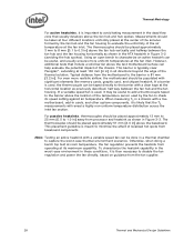
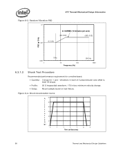
... minutes per axis) (20, 0.02) (500, 0.02) PSD (g^2/Hz) 0.001 1 5 Hz 10 100 Frequency (Hz) 500 Hz 1000 6.3.1.2 Shock Test Procedure Recommended performance requirement for a motherboard: • Quantity: 3 drops for + and - directions in each of 3 perpendicular axes (that is, total 18 drops). • Profile: 50 G trapezoidal waveform, 170 in/sec minimum...
... minutes per axis) (20, 0.02) (500, 0.02) PSD (g^2/Hz) 0.001 1 5 Hz 10 100 Frequency (Hz) 500 Hz 1000 6.3.1.2 Shock Test Procedure Recommended performance requirement for a motherboard: • Quantity: 3 drops for + and - directions in each of 3 perpendicular axes (that is, total 18 drops). • Profile: 50 G trapezoidal waveform, 170 in/sec minimum...
Mechanical Design Guidelines
Page 57
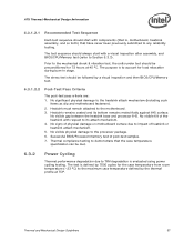
... of heatsink or heatsink attach mechanism. 5. No visible gap between the heatsink base and processor IHS. No signs of physical damage on motherboard surface due to the motherboard. 3. No visible physical damage to the heatsink attach mechanism (including such items as clip... 6.3.2 Power Cycling Thermal performance degradation due to TIM degradation is , motherboard, heatsink assembly, and so forth) that is evaluated using power cycling testing. No significant physical damage to the processor package. 6. Thermal compliance testing to demonstrate that the case temperature specification...
... of heatsink or heatsink attach mechanism. 5. No visible gap between the heatsink base and processor IHS. No signs of physical damage on motherboard surface due to the motherboard. 3. No visible physical damage to the heatsink attach mechanism (including such items as clip... 6.3.2 Power Cycling Thermal performance degradation due to TIM degradation is , motherboard, heatsink assembly, and so forth) that is evaluated using power cycling testing. No significant physical damage to the processor package. 6. Thermal compliance testing to demonstrate that the case temperature specification...
Mechanical Design Guidelines
Page 58
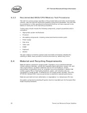
Testing setup should include the following components, properly assembled and/or connected: • Appropriate system motherboard • Processor • All enabling components, including socket and thermal solution parts • Power supply • Disk drive • Video ...components assembled. Any plastic component exceeding 25 grams must be conducted on a fully operational motherboard that the system under test shall successfully complete the checking of BIOS, basic processor functions and memory, without any battery of non-resistant materials include cellulose materials, animal ...
Testing setup should include the following components, properly assembled and/or connected: • Appropriate system motherboard • Processor • All enabling components, including socket and thermal solution parts • Power supply • Disk drive • Video ...components assembled. Any plastic component exceeding 25 grams must be conducted on a fully operational motherboard that the system under test shall successfully complete the checking of BIOS, basic processor functions and memory, without any battery of non-resistant materials include cellulose materials, animal ...
Mechanical Design Guidelines
Page 59
...include height restrictions in the ATX Specification revision 2.1 and the microATX Motherboard Interface Specification revision 1.1 found in Appendix G provides detailed reference ATX/μATX motherboard keep-out information for Intel® Reference ATX Thermal Mechanical Design Figure 7-40, Figure 7-41..., and Figure 7-42 in both ATX Specification V2.1 and microATX Motherboard Interface Specification V1.1 documents. ATX Thermal/...
...include height restrictions in the ATX Specification revision 2.1 and the microATX Motherboard Interface Specification revision 1.1 found in Appendix G provides detailed reference ATX/μATX motherboard keep-out information for Intel® Reference ATX Thermal Mechanical Design Figure 7-40, Figure 7-41..., and Figure 7-42 in both ATX Specification V2.1 and microATX Motherboard Interface Specification V1.1 documents. ATX Thermal/...

