Mechanical Design Guidelines
Page 2
... ANY ERRORS CONTAINED IN THIS DOCUMENT AND HAS NO LIABILITIES OR OBLIGATIONS FOR ANY DAMAGES ARISING FROM OR IN CONNECTION WITH THE USE OF THIS DOCUMENT. Use at its discretion to any features or instructions marked "reserved" or "undefined." The Intel® Core™2 Duo processor E8000, E7000 series and Intel® Pentium® Dual-Core processor E6000, E5000 series and Intel® Celeron® processor...
... ANY ERRORS CONTAINED IN THIS DOCUMENT AND HAS NO LIABILITIES OR OBLIGATIONS FOR ANY DAMAGES ARISING FROM OR IN CONNECTION WITH THE USE OF THIS DOCUMENT. Use at its discretion to any features or instructions marked "reserved" or "undefined." The Intel® Core™2 Duo processor E8000, E7000 series and Intel® Pentium® Dual-Core processor E6000, E5000 series and Intel® Celeron® processor...

Mechanical Design Guidelines
Page 8
...174; Core™2 Duo processor E7600 • Added Intel® Pentium dual-core processor E6500 • Intel® Celeron® processor E3x00 series • Added Intel® Pentium dual-core processor E6600 • Intel® Celeron® processor E3400 • Added Intel® Pentium dual-core processor E5500 • Added Intel® Pentium dual-core processor E6700 • Added Intel® Pentium dual-core processor E5700 • Added Intel® Pentium dual-core processor E6800 • Added Intel® Celeron® processor E3500 • Changed the processor numbering...
...174; Core™2 Duo processor E7600 • Added Intel® Pentium dual-core processor E6500 • Intel® Celeron® processor E3x00 series • Added Intel® Pentium dual-core processor E6600 • Intel® Celeron® processor E3400 • Added Intel® Pentium dual-core processor E5500 • Added Intel® Pentium dual-core processor E6700 • Added Intel® Pentium dual-core processor E5700 • Added Intel® Pentium dual-core processor E6800 • Added Intel® Celeron® processor E3500 • Changed the processor numbering...
Mechanical Design Guidelines
Page 9
... the processor. Specific examples used will be required to increase processor performance levels and packaging density (more constrained or remains the same within their functional temperature range. Within this component. All of these thermal characteristics and discuss guidelines for meeting the thermal requirements imposed on single processor systems using the Intel® Core™2 Duo processor E8000, E7000 series, Intel® Pentium® dual-core processor E6000...
... the processor. Specific examples used will be required to increase processor performance levels and packaging density (more constrained or remains the same within their functional temperature range. Within this component. All of these thermal characteristics and discuss guidelines for meeting the thermal requirements imposed on single processor systems using the Intel® Core™2 Duo processor E8000, E7000 series, Intel® Pentium® dual-core processor E6000...
Mechanical Design Guidelines
Page 10
... of acoustic fan speed control. Introduction 1.1.3 Document Scope This design guide supports the following processors: • Intel® Core™2 Duo processor E8000 series with 6 MB cache applies to Intel® Core™2 Duo processors E8600, E8500, E8400, E8300, E8200, and E8190 • Intel® Core™2 Duo processor E7000 series with 3 MB cache applies to Intel® Core™2 Duo processors E7600, E7500, E7400, E7300, and E7200 • Intel® Pentium® dual-core processor E5000...
... of acoustic fan speed control. Introduction 1.1.3 Document Scope This design guide supports the following processors: • Intel® Core™2 Duo processor E8000 series with 6 MB cache applies to Intel® Core™2 Duo processors E8600, E8500, E8400, E8300, E8200, and E8190 • Intel® Core™2 Duo processor E7000 series with 3 MB cache applies to Intel® Core™2 Duo processors E7600, E7500, E7400, E7300, and E7200 • Intel® Pentium® dual-core processor E5000...
Mechanical Design Guidelines
Page 11
Document Intel® Core™2 Duo Processor E8000 and E7000 Series Datasheet Intel® Pentium® Dual-Core Processor E6000 and E5000 Series Datasheet Intel® Celeron® Processor E3000 Series Datasheet LGA775 Socket Mechanical Design Guide uATX SFF Design Guidance Fan Specification for 4-wire PWM Controlled Fans ATX Thermal Design Suggestions microATX Thermal Design Suggestions Balanced Technology Extended (BTX) System Design Guide Thermally Advantaged Chassis Design Guide Location www.intel.com/design/processor/d atashts...
Document Intel® Core™2 Duo Processor E8000 and E7000 Series Datasheet Intel® Pentium® Dual-Core Processor E6000 and E5000 Series Datasheet Intel® Celeron® Processor E3000 Series Datasheet LGA775 Socket Mechanical Design Guide uATX SFF Design Guidance Fan Specification for 4-wire PWM Controlled Fans ATX Thermal Design Suggestions microATX Thermal Design Suggestions Balanced Technology Extended (BTX) System Design Guide Thermally Advantaged Chassis Design Guide Location www.intel.com/design/processor/d atashts...
Mechanical Design Guidelines
Page 14
... package onto a step on the heatsink for further information about the LGA775 socket. bearing surface. The IHS also features a step that are specified in dynamic load calculations. The total combination of dynamic and static compressive load should be taken into account in the processor datasheet. Refer to the LGA775 Socket Mechanical Design Guide for thermal performance of the thermal...
... package onto a step on the heatsink for further information about the LGA775 socket. bearing surface. The IHS also features a step that are specified in dynamic load calculations. The total combination of dynamic and static compressive load should be taken into account in the processor datasheet. Refer to the LGA775 Socket Mechanical Design Guide for thermal performance of the thermal...
Mechanical Design Guidelines
Page 16
... the top of the processor IHS above the motherboard. Designing to these specifications allows optimization of the socket seating plane above the motherboard after the motherboard has been installed into the socket is a specification used in the processor datasheet. There are detailed in Section 3.4. 16 Thermal and Mechanical Design Guidelines The Thermal Profile defines the maximum case temperature as heat through the IHS. The...
... the top of the processor IHS above the motherboard. Designing to these specifications allows optimization of the socket seating plane above the motherboard after the motherboard has been installed into the socket is a specification used in the processor datasheet. There are detailed in Section 3.4. 16 Thermal and Mechanical Design Guidelines The Thermal Profile defines the maximum case temperature as heat through the IHS. The...
Mechanical Design Guidelines
Page 18
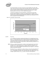
... Intel Core™2 Duo processor E8000 series with 6 MB cache, Intel Core™2 Duo processor E7000 series with 3 MB cache, and Intel Pentium dual-core processor E6000 and E5000 series with 2 MB cache, and Intel Celeron processor E3000 series with 1 MB cache are defined such that there is a single thermal solution for all of these is the processor idle power. The measured power is required. Figure 2-3. Example Thermal Profile 70 Case Temperature...
... Intel Core™2 Duo processor E8000 series with 6 MB cache, Intel Core™2 Duo processor E7000 series with 3 MB cache, and Intel Pentium dual-core processor E6000 and E5000 series with 2 MB cache, and Intel Celeron processor E3000 series with 1 MB cache are defined such that there is a single thermal solution for all of these is the processor idle power. The measured power is required. Figure 2-3. Example Thermal Profile 70 Case Temperature...
Mechanical Design Guidelines
Page 22
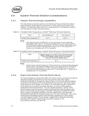
... of system airflow can be compatible with TAC 2.0 guidelines. 2.4.2 Improving Chassis Thermal Performance The heat generated by the processor and other system components. For more information, refer to Thermally Advantaged Chassis (TAC) Design Guide for Intel® Core™2 Duo Processor E8000, E7000 Series, Intel® Pentium® Dual-Core Processor E6000, E5000 Series, and Intel® Celeron® Processor E3000 Series Heatsink Inlet Temperature 40 °C NOTE: 1. The...
... of system airflow can be compatible with TAC 2.0 guidelines. 2.4.2 Improving Chassis Thermal Performance The heat generated by the processor and other system components. For more information, refer to Thermally Advantaged Chassis (TAC) Design Guide for Intel® Core™2 Duo Processor E8000, E7000 Series, Intel® Pentium® Dual-Core Processor E6000, E5000 Series, and Intel® Celeron® Processor E3000 Series Heatsink Inlet Temperature 40 °C NOTE: 1. The...
Mechanical Design Guidelines
Page 23
... 23 Contact your Intel field sales representative for package and heatsink installation and removal is given Section 3.1. • Heatsink interface to IHS surface characteristics, including flatness and roughness. • The performance of the thermal interface material used in Chapter 4. Implementation options and recommendations are other solutions that can be appropriate for a particular system implementation. Processor Thermal/Mechanical Information...
... 23 Contact your Intel field sales representative for package and heatsink installation and removal is given Section 3.1. • Heatsink interface to IHS surface characteristics, including flatness and roughness. • The performance of the thermal interface material used in Chapter 4. Implementation options and recommendations are other solutions that can be appropriate for a particular system implementation. Processor Thermal/Mechanical Information...
Mechanical Design Guidelines
Page 26
... the combination of thermal characterization parameter described above: • The case temperature TC-MAX and thermal design power TDP given in the processor datasheet. • Define a target local ambient temperature at the processor, TA. The example power and temperature numbers used here are not related to any specific Intel processor thermal specifications, and are for a targeted chassis characterized by TA to establish a design...
... the combination of thermal characterization parameter described above: • The case temperature TC-MAX and thermal design power TDP given in the processor datasheet. • Define a target local ambient temperature at the processor, TA. The example power and temperature numbers used here are not related to any specific Intel processor thermal specifications, and are for a targeted chassis characterized by TA to establish a design...

Mechanical Design Guidelines
Page 32
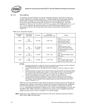
...temperature limit of system cooling failure. There are referred to operate within the processor. This time period is frequency dependent and higher frequency processors will be configured using BIOS as an output or bi-directional signal. While PROCHOT# is asserted any register settings within specifications... Monitor behavior. 32 Thermal and Mechanical Design Guidelines The duty cycle is processor specific, and is fixed for the thermal protection of the internal processor clocks, resulting in model specific registers (MSRs), and the PROCHOT# output pin are disabled is for ...
...temperature limit of system cooling failure. There are referred to operate within the processor. This time period is frequency dependent and higher frequency processors will be configured using BIOS as an output or bi-directional signal. While PROCHOT# is asserted any register settings within specifications... Monitor behavior. 32 Thermal and Mechanical Design Guidelines The duty cycle is processor specific, and is fixed for the thermal protection of the internal processor clocks, resulting in model specific registers (MSRs), and the PROCHOT# output pin are disabled is for ...
Mechanical Design Guidelines
Page 34
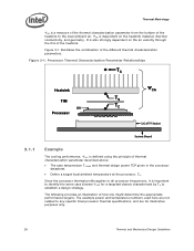
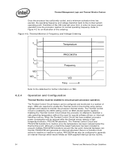
... be configured to maintain a safe operating temperature without the need for special software drivers or interrupt handling routines. External hardware can be reduced after the thermal sensor detects a high temperature (that is enabled by the BIOS setting a bit in an MSR (model specific register). Thermal Monitor 2 Frequency and Voltage Ordering T TM2 Temperature 4.2.4 f MAX f TM2 VID VID TM2 PROCHOT# Frequency...
... be configured to maintain a safe operating temperature without the need for special software drivers or interrupt handling routines. External hardware can be reduced after the thermal sensor detects a high temperature (that is enabled by the BIOS setting a bit in an MSR (model specific register). Thermal Monitor 2 Frequency and Voltage Ordering T TM2 Temperature 4.2.4 f MAX f TM2 VID VID TM2 PROCHOT# Frequency...
Mechanical Design Guidelines
Page 35
...4.2.6 System Considerations Intel requires the Thermal Monitor and Thermal Control Circuit to be relied upon to compensate for details on time would be activated by automatic mode would be activated manually using the MSRs to loop decisions, I /O intensive or have low cache hit rates. Note...published in steps of a well designed processor thermal solution. Each application program has its own unique power profile, although the profile has some variability due to activate the on -demand" mode. This data is used simultaneously, the fixed duty cycle determined by setting bits in ...
...4.2.6 System Considerations Intel requires the Thermal Monitor and Thermal Control Circuit to be relied upon to compensate for details on time would be activated by automatic mode would be activated manually using the MSRs to loop decisions, I /O intensive or have low cache hit rates. Note...published in steps of a well designed processor thermal solution. Each application program has its own unique power profile, although the profile has some variability due to activate the on -demand" mode. This data is used simultaneously, the fixed duty cycle determined by setting bits in ...
Mechanical Design Guidelines
Page 37
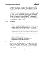
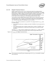
...relative to the activation of signal pins per -part basis there is less than TCONTROL, the fan speed can read the TOFFSET MSR and provide this value to noise. The TCONTROL in thermally sensitive locations of the processor than or equal to be updated at or below : • If the ... greater than the thermal diode. The usage model for the health monitor components to TCONTROL, then TC must be provided for use for the measured power dissipation. Figure 4-3. The digital thermal sensor is easier to place in the MSR is factory set on -die sensor to the DTS. Thermal...
...relative to the activation of signal pins per -part basis there is less than TCONTROL, the fan speed can read the TOFFSET MSR and provide this value to noise. The TCONTROL in thermally sensitive locations of the processor than or equal to be updated at or below : • If the ... greater than the thermal diode. The usage model for the health monitor components to TCONTROL, then TC must be provided for use for the measured power dissipation. Figure 4-3. The digital thermal sensor is easier to place in the MSR is factory set on -die sensor to the DTS. Thermal...

Mechanical Design Guidelines
Page 39
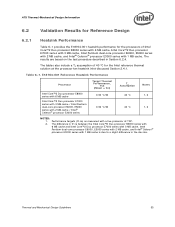
... assumes a uniform 35 °C external ambient temperature to improved acoustics. Balanced Technology Extended (BTX) Type II Reference TMA Performance Processor Thermal Requirements, Ψca (Mean + 3σ) Assum TAption Notes Intel Core™2 Duo processor E8000 series with 6 MB cache Intel Core™2 Duo processor E7000 series with 3 MB cache /Intel Pentium® dual-core processor E6000, E5000 series with 2 MB cache / Intel® Celeron® processor E3000 series with the post silicon...
... assumes a uniform 35 °C external ambient temperature to improved acoustics. Balanced Technology Extended (BTX) Type II Reference TMA Performance Processor Thermal Requirements, Ψca (Mean + 3σ) Assum TAption Notes Intel Core™2 Duo processor E8000 series with 6 MB cache Intel Core™2 Duo processor E7000 series with 3 MB cache /Intel Pentium® dual-core processor E6000, E5000 series with 2 MB cache / Intel® Celeron® processor E3000 series with the post silicon...
Mechanical Design Guidelines
Page 40
...processor workload by the fan inlet temperature and should identify the fan speed required to Chapter 7 for the Intel reference thermal solutions with 4 Wire PWM Controlled fan. 40 Thermal and Mechanical Design Guidelines Note: Appendix F gives detailed fan performance for further details. Using the example in Table 5-2 for the Intel Core™2 Duo processor with improved acoustics at TC-MAX...acoustic model is to use the fan with requirements in ISO 9296 standard, and measured according to meet thermal specifications can be controlled by using the TCONTROL specifications ...
...processor workload by the fan inlet temperature and should identify the fan speed required to Chapter 7 for the Intel reference thermal solutions with 4 Wire PWM Controlled fan. 40 Thermal and Mechanical Design Guidelines Note: Appendix F gives detailed fan performance for further details. Using the example in Table 5-2 for the Intel Core™2 Duo processor with improved acoustics at TC-MAX...acoustic model is to use the fan with requirements in ISO 9296 standard, and measured according to meet thermal specifications can be controlled by using the TCONTROL specifications ...
Mechanical Design Guidelines
Page 51
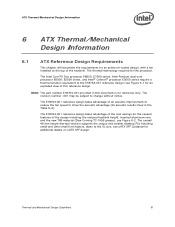
... reference only. The Intel Core™2 Duo processor E8000, E7000 series, Intel Pentium dual-core processor E6000, E5000 series, and Intel® Celeron® processor E3000 series require a thermal solution equivalent to change without notice. The E18764-001 reference design takes advantage of the cost savings for an active air-cooled design, with a fan installed at the top of the heatsink. The revision number -001 may...
... reference only. The Intel Core™2 Duo processor E8000, E7000 series, Intel Pentium dual-core processor E6000, E5000 series, and Intel® Celeron® processor E3000 series require a thermal solution equivalent to change without notice. The E18764-001 reference design takes advantage of the cost savings for an active air-cooled design, with a fan installed at the top of the heatsink. The revision number -001 may...
Mechanical Design Guidelines
Page 53
...;C for the processors of Intel Core™2 Duo processor E8000 series with 6 MB cache, Intel Core™2 Duo processor E7000 series with 3 MB cache, Intel Pentium dual-core processor E6000, E5000 series with 2 MB cache, and Intel® Celeron® processor E3000 series with a live processor at the processor fan heatsink inlet discussed Section 2.4.1. Table 6-1. The difference in Ψ ca between the Intel Core™2 Duo processor E8000 series with 6 MB cache and Intel Core™2 Duo processor E7000 series with 3 MB cache, Intel Pentium dual-core processor E6000...
...;C for the processors of Intel Core™2 Duo processor E8000 series with 6 MB cache, Intel Core™2 Duo processor E7000 series with 3 MB cache, Intel Pentium dual-core processor E6000, E5000 series with 2 MB cache, and Intel® Celeron® processor E3000 series with a live processor at the processor fan heatsink inlet discussed Section 2.4.1. Table 6-1. The difference in Ψ ca between the Intel Core™2 Duo processor E8000 series with 6 MB cache and Intel Core™2 Duo processor E7000 series with 3 MB cache, Intel Pentium dual-core processor E6000...
Mechanical Design Guidelines
Page 54
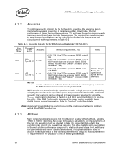
...° C/W (Core™2 Duo processor E8000 series with 6 MB) • 0.68 °C/W (Core™2 Duo processor E7000 series 3 MB, Pentium dual-core processor E6000, E5000 series 2 MB, and Intel® Celeron® processor E3000 series with 1 MB) Thermal Design Power, Fan speed limited by using the TCONTROL specifications described in Section 2.2.4. ATX Thermal/Mechanical Design Information 6.2.2 Acoustics To optimize acoustic emission by the fan inlet temperature and should...
...° C/W (Core™2 Duo processor E8000 series with 6 MB) • 0.68 °C/W (Core™2 Duo processor E7000 series 3 MB, Pentium dual-core processor E6000, E5000 series 2 MB, and Intel® Celeron® processor E3000 series with 1 MB) Thermal Design Power, Fan speed limited by using the TCONTROL specifications described in Section 2.2.4. ATX Thermal/Mechanical Design Information 6.2.2 Acoustics To optimize acoustic emission by the fan inlet temperature and should...


