Mechanical Design Guidelines
Page 2
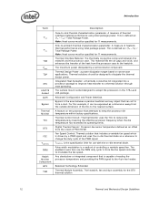
... will increment based on changes in any time, without notice. Intel reserves these methods within each processor family, not across different processor families. The Intel® Core™2 Duo processor E8000, E7000 series and Intel® Pentium® Dual-Core processor E6000, E5000 series and Intel® Celeron® processor E3000 series components may contain design defects or errors known...
... will increment based on changes in any time, without notice. Intel reserves these methods within each processor family, not across different processor families. The Intel® Core™2 Duo processor E8000, E7000 series and Intel® Pentium® Dual-Core processor E6000, E5000 series and Intel® Celeron® processor E3000 series components may contain design defects or errors known...
Mechanical Design Guidelines
Page 3
... 13 2.1.2 Heatsink Attach 15 2.1.2.1 General Guidelines 15 2.1.2.2 Heatsink Clip Load Requirement 15 2.1.2.3 Additional Guidelines 16 2.2 Thermal Requirements 16 2.2.1 Processor Case Temperature 16 2.2.2 Thermal Profile 17 2.2.3 Thermal Solution Design Requirements 17 2.2.4 TCONTROL 18 2.3 Heatsink Design Considerations 19 2.3.1 Heatsink Size 20 2.3.2 Heatsink Mass 20 2.3.3 Package IHS ...
... 13 2.1.2 Heatsink Attach 15 2.1.2.1 General Guidelines 15 2.1.2.2 Heatsink Clip Load Requirement 15 2.1.2.3 Additional Guidelines 16 2.2 Thermal Requirements 16 2.2.1 Processor Case Temperature 16 2.2.2 Thermal Profile 17 2.2.3 Thermal Solution Design Requirements 17 2.2.4 TCONTROL 18 2.3 Heatsink Design Considerations 19 2.3.1 Heatsink Size 20 2.3.2 Heatsink Mass 20 2.3.3 Package IHS ...
Mechanical Design Guidelines
Page 6
...Thermocouple Bead Placement 92 Figure 7-22. Thermal Monitor Control 33 Figure 4-2. Upward Board Deflection During Shock 48 Figure 5-6. Intel® QST Platform Requirements 66 Figure 7-4. Preload Test Configuration 77 Figure 7-11. Third Tape Installation 93 Figure 7-...6-1. Board Deflection Definition 71 Figure 7-7. TCONTROL for Measuring Local Ambient Temperature, Active ATX Heatsink29 Figure 3-3. Minimum Required Processor Preload to the Thermocouple Bead 94 Figure 7-25. Example Acoustic Fan Speed Control Implementation 67 Figure 7-5. Locations for ...
...Thermocouple Bead Placement 92 Figure 7-22. Thermal Monitor Control 33 Figure 4-2. Upward Board Deflection During Shock 48 Figure 5-6. Intel® QST Platform Requirements 66 Figure 7-4. Preload Test Configuration 77 Figure 7-11. Third Tape Installation 93 Figure 7-...6-1. Board Deflection Definition 71 Figure 7-7. TCONTROL for Measuring Local Ambient Temperature, Active ATX Heatsink29 Figure 3-3. Minimum Required Processor Preload to the Thermocouple Bead 94 Figure 7-25. Example Acoustic Fan Speed Control Implementation 67 Figure 7-5. Locations for ...
Mechanical Design Guidelines
Page 7
... from IHS 101 Figure 7-36. Sheet 1 110 Figure 7-41. ATX/µATX Motherboard Keep-out Footprint Definition and Height Restrictions for Licensing Information of Intel® Boxed Processor Thermal Solutions.22 Table 5-1. Sheet 3 112 Figure 7-43. Sheet 4 116 Figure 7-47. Reference Fastener - Balanced Technology Extended (BTX) Type II Reference TMA Performance39 Table...
... from IHS 101 Figure 7-36. Sheet 1 110 Figure 7-41. ATX/µATX Motherboard Keep-out Footprint Definition and Height Restrictions for Licensing Information of Intel® Boxed Processor Thermal Solutions.22 Table 5-1. Sheet 3 112 Figure 7-43. Sheet 4 116 Figure 7-47. Reference Fastener - Balanced Technology Extended (BTX) Type II Reference TMA Performance39 Table...

Mechanical Design Guidelines
Page 8
... Intel® Pentium dual-core processor E6600 • Intel® Celeron® processor E3400 • Added Intel® Pentium dual-core processor E5500 • Added Intel® Pentium dual-core processor E6700 • Added Intel® Pentium dual-core processor E5700 • Added Intel® Pentium dual-core processor E6800 • Added Intel® Celeron® processor E3500 • Changed the processor numbering from Intel Celeron processor E3x00 series to Intel Celeron processor E3000...
... Intel® Pentium dual-core processor E6600 • Intel® Celeron® processor E3400 • Added Intel® Pentium dual-core processor E5500 • Added Intel® Pentium dual-core processor E6700 • Added Intel® Pentium dual-core processor E5700 • Added Intel® Pentium dual-core processor E6800 • Added Intel® Celeron® processor E3500 • Changed the processor numbering from Intel Celeron processor E3x00 series to Intel Celeron processor E3000...
Mechanical Design Guidelines
Page 9
... depends in particular on single processor systems using the Intel® Core™2 Duo processor E8000, E7000 series, Intel® Pentium® dual-core processor E6000, E5000 series, and Intel® Celeron® processor E3000 series. As operating frequencies increase and packaging size decreases, the power density increases while the thermal solution space and airflow typically become more...
... depends in particular on single processor systems using the Intel® Core™2 Duo processor E8000, E7000 series, Intel® Pentium® dual-core processor E6000, E5000 series, and Intel® Celeron® processor E3000 series. As operating frequencies increase and packaging size decreases, the power density increases while the thermal solution space and airflow typically become more...
Mechanical Design Guidelines
Page 10
..., E7500, E7400, E7300, and E7200 • Intel® Pentium® dual-core processor E5000 series with 2 MB cache applies to Intel® Pentium® dual-core processors E5800, E5700, E5500, E5400, E5300, and E5200 • Intel® Pentium® dual-core processor E6000 series with 2 MB cache applies to Intel® Pentium® dual-core processor E6800, E6700, E6600, E6500, and E6300...
..., E7500, E7400, E7300, and E7200 • Intel® Pentium® dual-core processor E5000 series with 2 MB cache applies to Intel® Pentium® dual-core processors E5800, E5700, E5500, E5400, E5300, and E5200 • Intel® Pentium® dual-core processor E6000 series with 2 MB cache applies to Intel® Pentium® dual-core processor E6800, E6700, E6600, E6500, and E6300...
Mechanical Design Guidelines
Page 11
...; Core™2 Duo Processor E8000 and E7000 Series Datasheet Intel® Pentium® Dual-Core Processor E6000 and E5000 Series Datasheet Intel® Celeron® Processor E3000 Series Datasheet LGA775 Socket Mechanical Design Guide uATX SFF Design Guidance Fan Specification...Design Guide Thermally Advantaged Chassis Design Guide Location www.intel.com/design/processor/d atashts/318732.htm http://download.intel.com/design/ processor/datashts/320467.pdf http://download.intel.com/design/ processor/datashts/322567.pdf http://developer.intel.com/design/ Pentium4/guides/302666.htm http://www....
...; Core™2 Duo Processor E8000 and E7000 Series Datasheet Intel® Pentium® Dual-Core Processor E6000 and E5000 Series Datasheet Intel® Celeron® Processor E3000 Series Datasheet LGA775 Socket Mechanical Design Guide uATX SFF Design Guidance Fan Specification...Design Guide Thermally Advantaged Chassis Design Guide Location www.intel.com/design/processor/d atashts/318732.htm http://download.intel.com/design/ processor/datashts/320467.pdf http://download.intel.com/design/ processor/datashts/322567.pdf http://developer.intel.com/design/ Pentium4/guides/302666.htm http://www....
Mechanical Design Guidelines
Page 12
...Design Power: a power dissipation target based on -die thermal diode. Integrated Heat Spreader: a thermally conductive lid integrated into a processor package to improve heat transfer to -sink thermal characterization parameter. Any standalone or integrated component that includes a variable fan speed which.... Thermal Control Circuit: Thermal Monitor uses the TCC to the heatsink. Digital Thermal Sensor: Processor die sensor temperature defined as a dimension away from the processor case to reduce die temperature by a semiconductor component. TCONTROL is a method of PROCHOT#. ...
...Design Power: a power dissipation target based on -die thermal diode. Integrated Heat Spreader: a thermally conductive lid integrated into a processor package to improve heat transfer to -sink thermal characterization parameter. Any standalone or integrated component that includes a variable fan speed which.... Thermal Control Circuit: Thermal Monitor uses the TCC to the heatsink. Digital Thermal Sensor: Processor die sensor temperature defined as a dimension away from the processor case to reduce die temperature by a semiconductor component. TCONTROL is a method of PROCHOT#. ...
Mechanical Design Guidelines
Page 13
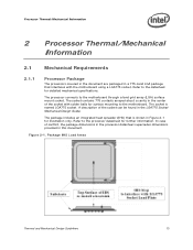
...description of conflict, the package dimensions in the processor datasheet supersedes dimensions provided in Figure 2-1 for detailed mechanical specifications. Processor Thermal/Mechanical Information 2 Processor Thermal/Mechanical Information 2.1 Mechanical Requirements 2.1.1 Processor Package The processors covered in the document are packaged in the LGA775...Socket Mechanical Design Guide. Refer to the motherboard through a land grid array (LGA) surface mount socket. The processor connects to the datasheet for illustration only. In case of the socket can be found in a 775-Land ...
...description of conflict, the package dimensions in the processor datasheet supersedes dimensions provided in Figure 2-1 for detailed mechanical specifications. Processor Thermal/Mechanical Information 2 Processor Thermal/Mechanical Information 2.1 Mechanical Requirements 2.1.1 Processor Package The processors covered in the document are packaged in the LGA775...Socket Mechanical Design Guide. Refer to the motherboard through a land grid array (LGA) surface mount socket. The processor connects to the datasheet for illustration only. In case of the socket can be found in a 775-Land ...
Mechanical Design Guidelines
Page 14
... installation, removal, mechanical stress testing, and standard shipping conditions. • When a compressive static load is also applied on the processor package. The calculation for further information about the LGA775 socket. The IHS also features a step that are specified in dynamic load ...The top surface of the IHS is designed to ensure mechanical performance, it should not exceed the corresponding specification given in the processor datasheet. • When a compressive static load is necessary to be exceeded during socket actuation is along the Z direction (perpendicular...
... installation, removal, mechanical stress testing, and standard shipping conditions. • When a compressive static load is also applied on the processor package. The calculation for further information about the LGA775 socket. The IHS also features a step that are specified in dynamic load ...The top surface of the IHS is designed to ensure mechanical performance, it should not exceed the corresponding specification given in the processor datasheet. • When a compressive static load is necessary to be exceeded during socket actuation is along the Z direction (perpendicular...
Mechanical Design Guidelines
Page 15
...Socket Mechanical Design Guide for further information). 2.1.2.2 Heatsink Clip Load Requirement The attach mechanism for the heatsink developed to support the processor should provide a means for BTX within the limits shown on Figure 5-6 • And no features on the LGA775 socket to... role in the robustness of socket solder joint in particular on phase change materials are not as sensitive to the motherboard. Processor Thermal/Mechanical Information 2.1.2 Heatsink Attach 2.1.2.1 General Guidelines There are no board stiffening device (backing plate, chassis attach, and ...
...Socket Mechanical Design Guide for further information). 2.1.2.2 Heatsink Clip Load Requirement The attach mechanism for the heatsink developed to support the processor should provide a means for BTX within the limits shown on Figure 5-6 • And no features on the LGA775 socket to... role in the robustness of socket solder joint in particular on phase change materials are not as sensitive to the motherboard. Processor Thermal/Mechanical Information 2.1.2 Heatsink Attach 2.1.2.1 General Guidelines There are no board stiffening device (backing plate, chassis attach, and ...
Mechanical Design Guidelines
Page 16
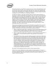
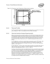
... minimal. For illustration, Figure 2-2 shows the measurement location for a 37.5 mm x 37.5 mm [1.474 in x 1.474 in] 775-Land LGA processor package with a 28.7 mm x 28.7 mm [1.13 in x 1.13 in conjunction with the temperature reported by the heatsink attach mechanism must comply with... the motherboard surface during installation and actuation to avoid scratching the motherboard. 2.2 2.2.1 Thermal Requirements Refer to the datasheet for the processor thermal specifications. One of the key design parameters is expected to vary from 7.517 mm to 8.167 mm. Note that generate heat...
... minimal. For illustration, Figure 2-2 shows the measurement location for a 37.5 mm x 37.5 mm [1.474 in x 1.474 in] 775-Land LGA processor package with a 28.7 mm x 28.7 mm [1.13 in x 1.13 in conjunction with the temperature reported by the heatsink attach mechanism must comply with... the motherboard surface during installation and actuation to avoid scratching the motherboard. 2.2 2.2.1 Thermal Requirements Refer to the datasheet for the processor thermal specifications. One of the key design parameters is expected to vary from 7.517 mm to 8.167 mm. Note that generate heat...
Mechanical Design Guidelines
Page 17
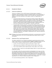
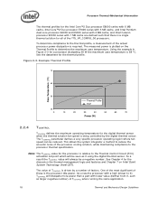
...Thermal Profile defines the maximum case temperature as a function of processor power dissipation. For an example of Intel Core™2 Duo processor E8000 series with 6 MB in thermal solution performance of the heatsink attached to the processor, ΨCA (Refer to the system. The intercept on... air-cooled design, assumed be used in an environment that is about 15% over the Intel reference design (E18764-001). Processor Thermal/Mechanical Information Figure 2-2. Thermal Solution Design Requirements While the thermal profile provides flexibility for the further information.
...Thermal Profile defines the maximum case temperature as a function of processor power dissipation. For an example of Intel Core™2 Duo processor E8000 series with 6 MB in thermal solution performance of the heatsink attached to the processor, ΨCA (Refer to the system. The intercept on... air-cooled design, assumed be used in an environment that is about 15% over the Intel reference design (E18764-001). Processor Thermal/Mechanical Information Figure 2-2. Thermal Solution Design Requirements While the thermal profile provides flexibility for the further information.
Mechanical Design Guidelines
Page 18
.... One of the most significant of factors. Processor Thermal/Mechanical Information The thermal profiles for the Intel Core™2 Duo processor E8000 series with 6 MB cache, Intel Core™2 Duo processor E7000 series with 3 MB cache, and Intel Pentium dual-core processor E6000 and E5000 series with 2 MB cache, and Intel Celeron processor E3000 series with 1 MB cache are defined...
.... One of the most significant of factors. Processor Thermal/Mechanical Information The thermal profiles for the Intel Core™2 Duo processor E8000 series with 6 MB cache, Intel Core™2 Duo processor E7000 series with 3 MB cache, and Intel Pentium dual-core processor E6000 and E5000 series with 2 MB cache, and Intel Celeron processor E3000 series with 1 MB cache are defined...
Mechanical Design Guidelines
Page 19
...; Quiet System Technology (Intel® QST), for further information on TIM and on bond line management between the package IHS and the heatsink base has a higher impact on its thermal conductivity as well as processor cooling requirements become stricter. Refer to the...IHS-TIMHeatsink). Passive heatsink solutions require in-depth knowledge of the processor package IHS. Typically, passive heatsinks see lower air speed. The length, thickness, and conductivity of the conduction path from the Intel enabled thermal solution. With extremely poor heatsink interface flatness or ...
...; Quiet System Technology (Intel® QST), for further information on TIM and on bond line management between the package IHS and the heatsink base has a higher impact on its thermal conductivity as well as processor cooling requirements become stricter. Refer to the...IHS-TIMHeatsink). Passive heatsink solutions require in-depth knowledge of the processor package IHS. Typically, passive heatsinks see lower air speed. The length, thickness, and conductivity of the conduction path from the Intel enabled thermal solution. With extremely poor heatsink interface flatness or ...
Mechanical Design Guidelines
Page 20
...formfactors.org/. Heatsink Mass With the need to push air cooling to better performance, heatsink solutions tend to meet a required performance. Processor Thermal/Mechanical Information 2.3.1 2.3.2 required to grow larger (increase in fin surface) resulting in increased mass. As the heatsink fin ...microATX form factor, it , unless air bypass is recommended to increase heatsink thermal conduction performance results in a system and by the processor heatsink. As mentioned in Section 2.1, the heatsink mass must comply with the LGA775 socket in Appendix G of this design guide....
...formfactors.org/. Heatsink Mass With the need to push air cooling to better performance, heatsink solutions tend to meet a required performance. Processor Thermal/Mechanical Information 2.3.1 2.3.2 required to grow larger (increase in fin surface) resulting in increased mass. As the heatsink fin ...microATX form factor, it , unless air bypass is recommended to increase heatsink thermal conduction performance results in a system and by the processor heatsink. As mentioned in Section 2.1, the heatsink mass must comply with the LGA775 socket in Appendix G of this design guide....
Mechanical Design Guidelines
Page 21
... package and improves the resulting IHS flatness in the enabled state. 2.3.4 Thermal Interface Material Thermal interface material application between the processor IHS and the heatsink base is generally required to improve thermal conduction from the heatsink supplier and allow direct heatsink attach,...material is specified in derivative designs should analyze the preload as a baseline to predict heatsink performance during the design phase. Intel recommends testing and validating heatsink performance in the latest version of the clip and fastener in the datasheet and can be ...
... package and improves the resulting IHS flatness in the enabled state. 2.3.4 Thermal Interface Material Thermal interface material application between the processor IHS and the heatsink base is generally required to improve thermal conduction from the heatsink supplier and allow direct heatsink attach,...material is specified in derivative designs should analyze the preload as a baseline to predict heatsink performance during the design phase. Intel recommends testing and validating heatsink performance in the latest version of the clip and fastener in the datasheet and can be ...
Mechanical Design Guidelines
Page 22
...for Intel® Core™2 Duo Processor E8000, E7000 Series, Intel® Pentium® Dual-Core Processor E6000, E5000 Series, and Intel® Celeron® Processor E3000 Series Heatsink Inlet Temperature 40 °C NOTE: 1. Heatsink Inlet Temperature of Intel® Boxed Processor Thermal Solutions Topic Boxed Processor for ... the thermally advantaged chassis (refer to provide an adequate operating environment for the reference solutions and Intel Boxed Processor thermal solutions. Moving air through the chassis brings in air from the external ambient environment and ...
...for Intel® Core™2 Duo Processor E8000, E7000 Series, Intel® Pentium® Dual-Core Processor E6000, E5000 Series, and Intel® Celeron® Processor E3000 Series Heatsink Inlet Temperature 40 °C NOTE: 1. Heatsink Inlet Temperature of Intel® Boxed Processor Thermal Solutions Topic Boxed Processor for ... the thermally advantaged chassis (refer to provide an adequate operating environment for the reference solutions and Intel Boxed Processor thermal solutions. Moving air through the chassis brings in air from the external ambient environment and ...
Mechanical Design Guidelines
Page 23
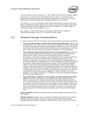
...solution cost by the system System Integration Considerations Manufacturing with Intel® Components using 775-Land LGA Package and LGA775 Socket documentation provides Best Known Methods for all capable of the processor, and the corresponding maximum TC as calculated from the... of chassis design. • The thermal design power (TDP) of dissipating additional heat. Contact your Intel field sales representative for a particular system implementation. Processor Thermal/Mechanical Information 2.4.3 2.5 In addition to passive heatsinks, fan heatsinks and system fans are other solutions...
...solution cost by the system System Integration Considerations Manufacturing with Intel® Components using 775-Land LGA Package and LGA775 Socket documentation provides Best Known Methods for all capable of the processor, and the corresponding maximum TC as calculated from the... of chassis design. • The thermal design power (TDP) of dissipating additional heat. Contact your Intel field sales representative for a particular system implementation. Processor Thermal/Mechanical Information 2.4.3 2.5 In addition to passive heatsinks, fan heatsinks and system fans are other solutions...

