

Product Guide
Page 1
Intel® Server Board SE7501BR2 Product Guide A Guide for Technically Qualified Assemblers of Intel® Identified Subassemblies/Products Order Number: A97020-002
Intel® Server Board SE7501BR2 Product Guide A Guide for Technically Qualified Assemblers of Intel® Identified Subassemblies/Products Order Number: A97020-002
Product Guide
Page 3
...Field Replaceable Units and Sensor Data Records 22 System Event Log ...22 Platform Event Management 22 Emergency Management Port 23 Intel® Server Management 24 Security ...25 Secure Mode ...26 Password Protection 27 Intrusion Switch Monitoring 28 Floppy Write Protection 28 Fixed ......32 Installing the I/O Gasket and Shield 32 Installing Chassis Standoffs 34 Installing the Rubber Bumper 35 Installing the Server Board 36 Making Connections to the Server Board 37 Cable Routing...38 Installing or Replacing Processor(s 39 Installing Memory ...52 Finishing Up ...53 Replacing the Back...
...Field Replaceable Units and Sensor Data Records 22 System Event Log ...22 Platform Event Management 22 Emergency Management Port 23 Intel® Server Management 24 Security ...25 Secure Mode ...26 Password Protection 27 Intrusion Switch Monitoring 28 Floppy Write Protection 28 Fixed ......32 Installing the I/O Gasket and Shield 32 Installing Chassis Standoffs 34 Installing the Rubber Bumper 35 Installing the Server Board 36 Making Connections to the Server Board 37 Cable Routing...38 Installing or Replacing Processor(s 39 Installing Memory ...52 Finishing Up ...53 Replacing the Back...

Product Guide
Page 4
... BIOS Upgrade 74 Changing the BIOS Language 75 Hot Keys ...75 4 Configuration Software and Utilities 77 System Software Update Sequence 77 Server Configuration Wizard 78 Direct Platform Control (DPC) Console 79 DPC Console Modes of Operation 80 Running the DPC Console 80 Using the... Setting a System Asset Tag 98 Creating Diskettes...98 Installing a Service Partition (Optional 99 Saving and Restoring Using the Intel Server tMheanSaygsetemmenCt oannfdigIunrtaetli®onS.M...a..R...T...T..o..o..l..(.O...p.t..io..n..a..l 110002 4 Intel Server Board SE7501BR2 Product Guide
... BIOS Upgrade 74 Changing the BIOS Language 75 Hot Keys ...75 4 Configuration Software and Utilities 77 System Software Update Sequence 77 Server Configuration Wizard 78 Direct Platform Control (DPC) Console 79 DPC Console Modes of Operation 80 Running the DPC Console 80 Using the... Setting a System Asset Tag 98 Creating Diskettes...98 Installing a Service Partition (Optional 99 Saving and Restoring Using the Intel Server tMheanSaygsetemmenCt oannfdigIunrtaetli®onS.M...a..R...T...T..o..o..l..(.O...p.t..io..n..a..l 110002 4 Intel Server Board SE7501BR2 Product Guide

Product Guide
Page 5
Installing Intel Server Management 103 Installing Intel SMaRT Tool 103 5 Solving Problems 105 Resetting the System ...105 Initial System Startup ...105 Checklist...105 Running New Application Software 106 Checklist...106 After the ... Does Not Light 110 Hard Disk Drive Activity Light Does Not Light 110 CD-ROM Drive Activity Light Does Not Light 110 Cannot Connect to a Server 110 Problems with Network 111 PCI Installation Tips 111 Problems with Application Software 111 Bootable CD-ROM Is Not Detected 111 Recovering the BIOS...112...
Installing Intel Server Management 103 Installing Intel SMaRT Tool 103 5 Solving Problems 105 Resetting the System ...105 Initial System Startup ...105 Checklist...105 Running New Application Software 106 Checklist...106 After the ... Does Not Light 110 Hard Disk Drive Activity Light Does Not Light 110 CD-ROM Drive Activity Light Does Not Light 110 Cannot Connect to a Server 110 Problems with Network 111 PCI Installation Tips 111 Problems with Application Software 111 Bootable CD-ROM Is Not Detected 111 Recovering the BIOS...112...
Product Guide
Page 6
...Figure 26. Installing Memory 52 Figure 27. Making Back Panel Connections 53 Figure 28. Front Panel Header Connection Location 120 6 Intel Server Board SE7501BR2 Product Guide Back Panel Connectors 12 Figure 3. Configuring Chassis Standoffs 34 Figure 7. Attaching the Heat Sink and Retention Clip 42... Figure 15. Attaching the Top Assembly to the Server Board 37 Figure 10. Installing the Heat Sink 50 Figure 25. CMOS Recovery Jumper 115 Figure 32. Configuration Jumper Location 119 Figure...
...Figure 26. Installing Memory 52 Figure 27. Making Back Panel Connections 53 Figure 28. Front Panel Header Connection Location 120 6 Intel Server Board SE7501BR2 Product Guide Back Panel Connectors 12 Figure 3. Configuring Chassis Standoffs 34 Figure 7. Attaching the Heat Sink and Retention Clip 42... Figure 15. Attaching the Top Assembly to the Server Board 37 Figure 10. Installing the Heat Sink 50 Figure 25. CMOS Recovery Jumper 115 Figure 32. Configuration Jumper Location 119 Figure...

Product Guide
Page 7
... 34. Table 8. Table 13. Table 14. Table 16. Table 20. Table 21. Table 23. Table 30. Table 7. Table 35. Server Board Features 9 64-bit PCI Segment Configuration 15 10/100 Megabit LEDs (NIC1 19 Gigabit LEDs (NIC2 19 Security Operation Summary 25 Keyboard Commands 59..., Embedded Devices Submenu 63 Peripheral Configuration Submenu 64 Memory Configuration Submenu 65 Advanced Chipset Control Submenu 65 Security Menu 66 Server Menu 67 System Management Submenu 68 Console Redirection Submenu 69 Event Log Configuration Submenu 70 Fault Resilient Booting Submenu 70 Boot...
... 34. Table 8. Table 13. Table 14. Table 16. Table 20. Table 21. Table 23. Table 30. Table 7. Table 35. Server Board Features 9 64-bit PCI Segment Configuration 15 10/100 Megabit LEDs (NIC1 19 Gigabit LEDs (NIC2 19 Security Operation Summary 25 Keyboard Commands 59..., Embedded Devices Submenu 63 Peripheral Configuration Submenu 64 Memory Configuration Submenu 65 Advanced Chipset Control Submenu 65 Security Menu 66 Server Menu 67 System Management Submenu 68 Console Redirection Submenu 69 Event Log Configuration Submenu 70 Fault Resilient Booting Submenu 70 Boot...

Product Guide
Page 9
...slots support full or half-length boards: • Two 64-bit, PCI-X 100 MHz expansion slots. The server board supports dual-processor operation with the Intel® E7501 chipset and the Intel® Xeon™ processors with 400 MHz • Intel® E7501 Chipset Memory Controller ...) or in the Interposer micro Pin Grid Array (INT-mPGA) package. 1 Description Server Board Features The Intel® Server Board SE7501BR2 offers a "flat" design, with the processors and memory subsystems residing on motherboard (M-ROMB) support provided via one slot is populated • Two 64-bit, PCI...
...slots support full or half-length boards: • Two 64-bit, PCI-X 100 MHz expansion slots. The server board supports dual-processor operation with the Intel® E7501 chipset and the Intel® Xeon™ processors with 400 MHz • Intel® E7501 Chipset Memory Controller ...) or in the Interposer micro Pin Grid Array (INT-mPGA) package. 1 Description Server Board Features The Intel® Server Board SE7501BR2 offers a "flat" design, with the processors and memory subsystems residing on motherboard (M-ROMB) support provided via one slot is populated • Two 64-bit, PCI...

Product Guide
Page 10
...; Floppy write-protect Form Factor Server Management1 IPMI 1.5 compliant • SSI-EEB 3.0 compliant form factor Intel® Baseboard Management Controller (BMC) Intel® Server Management (ISM) software Version 5.5,...Server Configuration Wizard (SCW) • Intel® SMaRT Tool Integration • Online Rolling BIOS & Firmware Upgrade • Command Line Interface over LAN • ID LED Server Management Support 1 For additional information refer to the Intel® Server Management ver 5.5 Installation & User's Guide available on the ISM CD. 10 Intel Server Board SE7501BR2...
...; Floppy write-protect Form Factor Server Management1 IPMI 1.5 compliant • SSI-EEB 3.0 compliant form factor Intel® Baseboard Management Controller (BMC) Intel® Server Management (ISM) software Version 5.5,...Server Configuration Wizard (SCW) • Intel® SMaRT Tool Integration • Online Rolling BIOS & Firmware Upgrade • Command Line Interface over LAN • ID LED Server Management Support 1 For additional information refer to the Intel® Server Management ver 5.5 Installation & User's Guide available on the ISM CD. 10 Intel Server Board SE7501BR2...
Product Guide
Page 12
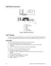
Keyboard / Mouse C. Parallel F. Back Panel Connectors Intel® Chipset The Intel® Server Board SE7501BR2 includes the Intel E7501 chipset (MCH, ICH3, P64H2), which provides an integrated I/O bridge and memory controller, and a... include the following: • Full support of registered ECC on the memory bus • Full support of Intel® x4 Single Device Data Correction on the memory interface with x4 DIMMs • Twelve deep in-order queue... data flow path to 8 GB of DDR memory • Memory scrubbing 12 Intel Server Board SE7501BR2 Product Guide USB 1, 2, 3 B. Video E.
Keyboard / Mouse C. Parallel F. Back Panel Connectors Intel® Chipset The Intel® Server Board SE7501BR2 includes the Intel E7501 chipset (MCH, ICH3, P64H2), which provides an integrated I/O bridge and memory controller, and a... include the following: • Full support of registered ECC on the memory bus • Full support of Intel® x4 Single Device Data Correction on the memory interface with x4 DIMMs • Twelve deep in-order queue... data flow path to 8 GB of DDR memory • Memory scrubbing 12 Intel Server Board SE7501BR2 Product Guide USB 1, 2, 3 B. Video E.

Product Guide
Page 13
The SE7501BR2 uses the following ICH3 features: • 32-bit/33 MHz PCI bus interface • Low Pin Count (LPC) bus interface • IDE interface, with Ultra ... panel connector. This port can be set to one of the PCI-X segments of the P64H2. A DH10 10-pin serial header is available on the SE7501BR2 server board. This device provides the system with ACPI-Compliant Controller/Extender is used as an Emergency Management Port. ICH3 I/O Controller Hub The primary role of the...
The SE7501BR2 uses the following ICH3 features: • 32-bit/33 MHz PCI bus interface • Low Pin Count (LPC) bus interface • IDE interface, with Ultra ... panel connector. This port can be set to one of the PCI-X segments of the P64H2. A DH10 10-pin serial header is available on the SE7501BR2 server board. This device provides the system with ACPI-Compliant Controller/Extender is used as an Emergency Management Port. ICH3 I/O Controller Hub The primary role of the...

Product Guide
Page 14
...The processor subsystem includes a single VR (Voltage Regulator) to the instructions provided in this chassis, see : http://support.intel.com/support/motherboards/server/SE7501BR2 Dual Processor Operation The Intel Xeon processor interface is installed, it should be of identical revision, core voltage, and bus/core speeds. Interrupt generation... the fan heat sink to the floppy disk drive from the floppy disk controller. Processor(s) The Intel® Server Board SE7501BR2 accommodates one processor is dual-processor (DP)-ready. The processors interface with the system bus at each boxed...
...The processor subsystem includes a single VR (Voltage Regulator) to the instructions provided in this chassis, see : http://support.intel.com/support/motherboards/server/SE7501BR2 Dual Processor Operation The Intel Xeon processor interface is installed, it should be of identical revision, core voltage, and bus/core speeds. Interrupt generation... the fan heat sink to the floppy disk drive from the floppy disk controller. Processor(s) The Intel® Server Board SE7501BR2 accommodates one processor is dual-processor (DP)-ready. The processors interface with the system bus at each boxed...
Product Guide
Page 15
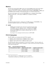
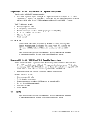
...size is 8 GB using four 2 GB DIMMs. ✏ NOTE DIMMs must be identical within the banks. Memory The Intel® Server Board SE7501BR2 contains four 184-pin DIMM sockets and provides support for up to four ECC DDR DIMMs that bus determines the bus ...bit wide data path via Slot 4. For a list of DDR266 memory. Although the SE7501BR2 server board architecture allows the user to 8 GB of tested memory, see: http://support.intel.com/support/motherboards/server/SE7501BR2 PCI I/O Subsystem The SE7501BR2 server board provides three PCI bus segments: • Segment C with two PCI-X 64-bit /...
...size is 8 GB using four 2 GB DIMMs. ✏ NOTE DIMMs must be identical within the banks. Memory The Intel® Server Board SE7501BR2 contains four 184-pin DIMM sockets and provides support for up to four ECC DDR DIMMs that bus determines the bus ...bit wide data path via Slot 4. For a list of DDR266 memory. Although the SE7501BR2 server board architecture allows the user to 8 GB of tested memory, see: http://support.intel.com/support/motherboards/server/SE7501BR2 PCI I/O Subsystem The SE7501BR2 server board provides three PCI bus segments: • Segment C with two PCI-X 64-bit /...
Product Guide
Page 16
... PCI-X features include: • Bus speed up to 100 MHz • 3.3 V signaling environment • Burst transfers up to the speed of the slowest adapter. 16 Intel Server Board SE7501BR2 Product Guide These slots are backward compatible to the speed of the slowest adapter. If you install a slower card into one of the PCI-X 64...
... PCI-X features include: • Bus speed up to 100 MHz • 3.3 V signaling environment • Burst transfers up to the speed of the slowest adapter. 16 Intel Server Board SE7501BR2 Product Guide These slots are backward compatible to the speed of the slowest adapter. If you install a slower card into one of the PCI-X 64...
Product Guide
Page 17
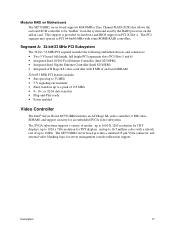
...-length, full height PCI expansion slots (PCI Slots 5 and 6) • Integrated Intel 10/100 Fast Ethernet Controller (Intel 82550PM) • Integrated Intel Gigabit Ethernet Controller (Intel 82540EM) • Integrated ATI Rage XL video controller with some ROMB RAID controllers. Modular RAID on Motherboard The SE7501BR2 server board supports M-ROMB or Zero Channel RAID (ZCR) that allows the on...
...-length, full height PCI expansion slots (PCI Slots 5 and 6) • Integrated Intel 10/100 Fast Ethernet Controller (Intel 82550PM) • Integrated Intel Gigabit Ethernet Controller (Intel 82540EM) • Integrated ATI Rage XL video controller with some ROMB RAID controllers. Modular RAID on Motherboard The SE7501BR2 server board supports M-ROMB or Zero Channel RAID (ZCR) that allows the on...

Product Guide
Page 18
... • Early receive interrupt for concurrent processing of the system, the gigabit controller is the designated Intel Server Management NIC. 18 Intel Server Board SE7501BR2 Product Guide You can disable the embedded NICs in BIOS Setup Utility. Facing the rear of receive ...2.2 • Chained memory structure, with a shielded LAN cable. Network Interface Controllers (NICs) The Intel® Server Board SE7501BR2 includes one 10/100Base-TX network connection, based on the Intel 82550PM Fast Ethernet Controller (NIC1)5, and one 10/100/1000Base-TX network connection, based on LAN ...
... • Early receive interrupt for concurrent processing of the system, the gigabit controller is the designated Intel Server Management NIC. 18 Intel Server Board SE7501BR2 Product Guide You can disable the embedded NICs in BIOS Setup Utility. Facing the rear of receive ...2.2 • Chained memory structure, with a shielded LAN cable. Network Interface Controllers (NICs) The Intel® Server Board SE7501BR2 includes one 10/100Base-TX network connection, based on the Intel 82550PM Fast Ethernet Controller (NIC1)5, and one 10/100/1000Base-TX network connection, based on LAN ...

Product Guide
Page 19
... On Blinking NIC1 State 10-Mbps 100-Mbps On Transmit / Receive activity NIC2 drives two LEDs located on the LAN and the speed of the board. Table 4. Gigabit LEDs (NIC2) LED Color LED State Off Green/Yellow (left side when looking at the I/O area at the I/O area ...link/activity on its RJ45 connector. This connector is yellow. See the following table for an overview. NIC Connector and Status LEDs The Intel® Server Board SE7501BR2 supports two RJ45 connectors, one for the 10/100-Megabit Fast Ethernet controller (NIC1), and the other for an overview. NIC1 drives ...
... On Blinking NIC1 State 10-Mbps 100-Mbps On Transmit / Receive activity NIC2 drives two LEDs located on the LAN and the speed of the board. Table 4. Gigabit LEDs (NIC2) LED Color LED State Off Green/Yellow (left side when looking at the I/O area at the I/O area ...link/activity on its RJ45 connector. This connector is yellow. See the following table for an overview. NIC Connector and Status LEDs The Intel® Server Board SE7501BR2 supports two RJ45 connectors, one for the 10/100-Megabit Fast Ethernet controller (NIC1), and the other for an overview. NIC1 drives ...
Product Guide
Page 20
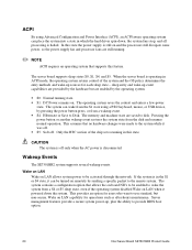
When the server board is operating in this state. This assumes that supports this state the power supply is still on ...remote system. The operating system saves the context and enters a low-power state. This provides an option for each sleep state - The server board supports sleep states S0, S1, S4, and S5. ACPI By using a PS/2 keyboard, mouse, or USB device, by pressing the ... state using Advanced Configuration and Power Interface (ACPI), an ACPI-aware operating system can be turned on -board NICs to provide BIOS boot option. 20 Intel Server Board SE7501BR2 Product Guide
When the server board is operating in this state. This assumes that supports this state the power supply is still on ...remote system. The operating system saves the context and enters a low-power state. This provides an option for each sleep state - The server board supports sleep states S0, S1, S4, and S5. ACPI By using a PS/2 keyboard, mouse, or USB device, by pressing the ... state using Advanced Configuration and Power Interface (ACPI), an ACPI-aware operating system can be turned on -board NICs to provide BIOS boot option. 20 Intel Server Board SE7501BR2 Product Guide

Product Guide
Page 21
Wake on RTC Alarm Wake on ). Baseboard Management Controller Intel server boards incorporate a baseboard management controller (BMC), which is a dedicated microcontroller for the system event log (SEL), sensor data records (SDRs), and baseboard field-replaceable unit... clock alarm when this option is enabled in Serial B if this option is enabled in the S1 or S4 state, it can be activated through Intel® Server Management (ISM) software version 5.5. The BMC performs the following functions: • Monitors system components and sensors, including processors, memory, fans, power ...
Wake on RTC Alarm Wake on ). Baseboard Management Controller Intel server boards incorporate a baseboard management controller (BMC), which is a dedicated microcontroller for the system event log (SEL), sensor data records (SDRs), and baseboard field-replaceable unit... clock alarm when this option is enabled in Serial B if this option is enabled in the S1 or S4 state, it can be activated through Intel® Server Management (ISM) software version 5.5. The BMC performs the following functions: • Monitors system components and sensors, including processors, memory, fans, power ...
Product Guide
Page 22
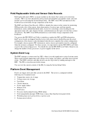
... sensors, their characteristics, location, type, and type-specific information, such as board serial number, part number, name, and asset tag-that contain active electronic circuitry. Intel® server boards are major modules in the system for converting a sensor reading into the appropriate...the front panel switch • Watchdog timer reset, power down, or power cycle • System restart (reboot) 22 Intel Server Board SE7501BR2 Product Guide The BIOS, software, and other devices can store information-such as default threshold values, factors for monitoring. Platform...
... sensors, their characteristics, location, type, and type-specific information, such as board serial number, part number, name, and asset tag-that contain active electronic circuitry. Intel® server boards are major modules in the system for converting a sensor reading into the appropriate...the front panel switch • Watchdog timer reset, power down, or power cycle • System restart (reboot) 22 Intel Server Board SE7501BR2 Product Guide The BIOS, software, and other devices can store information-such as default threshold values, factors for monitoring. Platform...

Product Guide
Page 23
EMP and Serial Over LAN The Serial B port 10-pin header on the board can be configured in Intel Server Management. If you have configured the Serial B port for use as an Emergency Management Port, or for serial output redirection over a LAN. At all... in several different ways: as a standard serial port, as an emergency management port and set it to a predefined destination on your configuration. Use the Server Configuration Wizard to the emergency management port (Serial B). You can configure these forms: • Platform Event Pages - The operating system will be able to...
EMP and Serial Over LAN The Serial B port 10-pin header on the board can be configured in Intel Server Management. If you have configured the Serial B port for use as an Emergency Management Port, or for serial output redirection over a LAN. At all... in several different ways: as a standard serial port, as an emergency management port and set it to a predefined destination on your configuration. Use the Server Configuration Wizard to the emergency management port (Serial B). You can configure these forms: • Platform Event Pages - The operating system will be able to...


