
Product Guide
Page 3
... 23 Intel® Server Management 24 Security ...25 Secure Mode ...26 Password Protection 27 Intrusion Switch Monitoring 28 Floppy Write Protection 28 Fixed Disk Boot Sector Write Protect 28 Power Switch Mask ...28 2 Server Board Installations and ...Requirements 31 Installation Notes...31 Installation Procedures...32 Installing the I/O Gasket and Shield 32 Installing Chassis Standoffs 34 Installing the Rubber Bumper 35 Installing the Server Board 36 Making Connections to the Server Board 37 Cable Routing...38 Installing or Replacing Processor(s 39 Installing Memory ...52 Finishing...
... 23 Intel® Server Management 24 Security ...25 Secure Mode ...26 Password Protection 27 Intrusion Switch Monitoring 28 Floppy Write Protection 28 Fixed Disk Boot Sector Write Protect 28 Power Switch Mask ...28 2 Server Board Installations and ...Requirements 31 Installation Notes...31 Installation Procedures...32 Installing the I/O Gasket and Shield 32 Installing Chassis Standoffs 34 Installing the Rubber Bumper 35 Installing the Server Board 36 Making Connections to the Server Board 37 Cable Routing...38 Installing or Replacing Processor(s 39 Installing Memory ...52 Finishing...
Product Guide
Page 6
...Fan to the Retention Mechanism 45 Figure 18. Attaching the Top Assembly to the Top of the PWT 44 Figure 17. Installing Memory 52 Figure 27. Configuration Jumper Location 119 Figure 33. Attaching the Label to the I/O Shield 32 Figure 4. Replacing the... Thermal Grease 41 Figure 14. Configuring Chassis Standoffs 34 Figure 7. Installing the Rubber Bumper 35 Figure 8. Installing the Heat Sink Clip 51 Figure 26. Front Panel Header Connection Location 120 6 Intel Server Board SE7501BR2 Product Guide Raising the Locking Bar 48 Figure 21. Password Recovery ...
...Fan to the Retention Mechanism 45 Figure 18. Attaching the Top Assembly to the Top of the PWT 44 Figure 17. Installing Memory 52 Figure 27. Configuration Jumper Location 119 Figure 33. Attaching the Label to the I/O Shield 32 Figure 4. Replacing the... Thermal Grease 41 Figure 14. Configuring Chassis Standoffs 34 Figure 7. Installing the Rubber Bumper 35 Figure 8. Installing the Heat Sink Clip 51 Figure 26. Front Panel Header Connection Location 120 6 Intel Server Board SE7501BR2 Product Guide Raising the Locking Bar 48 Figure 21. Password Recovery ...
Product Guide
Page 15
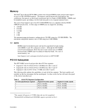
... ECC DDR DIMMs that bus determines the bus mode/speed. The memory subsystem provides dual memory bus architecture; The least capable card installed on the board is provided via two separate memory buses. For a list of tested memory, see: http://support.intel.com/support/motherboards/server/SE7501BR2 PCI I/O Subsystem The SE7501BR2 server board provides three PCI bus segments: • Segment C with two PCI...
... ECC DDR DIMMs that bus determines the bus mode/speed. The memory subsystem provides dual memory bus architecture; The least capable card installed on the board is provided via two separate memory buses. For a list of tested memory, see: http://support.intel.com/support/motherboards/server/SE7501BR2 PCI I/O Subsystem The SE7501BR2 server board provides three PCI bus segments: • Segment C with two PCI...

Product Guide
Page 31
... supported processors, see : http://support.intel.com/support/motherboards/server/SE7501BR2 Processor Minimum of 450 W. Minimum Hardware Requirements To avoid integration difficulties and possible board damage, your chassis manual Page 40 Page 47 Page 52 Server Board Installation and Upgrades 31 For a list of qualified memory and chassis components see : http://support.intel.com/support/motherboards/server/SE7501BR2 Memory Minimum of two 128 MB...
... supported processors, see : http://support.intel.com/support/motherboards/server/SE7501BR2 Processor Minimum of 450 W. Minimum Hardware Requirements To avoid integration difficulties and possible board damage, your chassis manual Page 40 Page 47 Page 52 Server Board Installation and Upgrades 31 For a list of qualified memory and chassis components see : http://support.intel.com/support/motherboards/server/SE7501BR2 Memory Minimum of two 128 MB...
Product Guide
Page 52
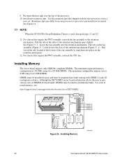
...the PWT assembly, reattach the CPU fan. For chassis that shipped with DIMM 1A and 1B (contiguous sockets). Installing Memory OM14665 52 Intel Server Board SE7501BR2 Product Guide Pull the tabs at the bottom of the retention mechanism apart slightly. Pull out on the tabs ...DIMMs must be identical within the banks. Although the SE7501BR2 server board architecture allows the user to the retention mechanism. 9. Re-insert the heat sink over the top of tested memory, see: http://support.intel.com/support/motherboards/server/SE7501BR2 DIMM 1A DIMM 1B DIMM 2A DIMM 2B Figure ...
...the PWT assembly, reattach the CPU fan. For chassis that shipped with DIMM 1A and 1B (contiguous sockets). Installing Memory OM14665 52 Intel Server Board SE7501BR2 Product Guide Pull the tabs at the bottom of the retention mechanism apart slightly. Pull out on the tabs ...DIMMs must be identical within the banks. Although the SE7501BR2 server board architecture allows the user to the retention mechanism. 9. Re-insert the heat sink over the top of tested memory, see: http://support.intel.com/support/motherboards/server/SE7501BR2 DIMM 1A DIMM 1B DIMM 2A DIMM 2B Figure ...

Product Guide
Page 57
...the BIOS Setup Utility This chapter describes the Power-On Self-Test (POST) and the BIOS Setup utility. Boot the server. 2. During the memory test, POST displays the amount of memory installed. 1. Write down both the screen display and the beep code you do not press or and do one . ...Use the arrow keys to test memory depends on your service representative. The changes are not saved for your server and monitor. For a listing ...
...the BIOS Setup Utility This chapter describes the Power-On Self-Test (POST) and the BIOS Setup utility. Boot the server. 2. During the memory test, POST displays the amount of memory installed. 1. Write down both the screen display and the beep code you do not press or and do one . ...Use the arrow keys to test memory depends on your service representative. The changes are not saved for your server and monitor. For a listing ...
Product Guide
Page 60
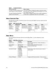
... Selections Feature Choices System Time HH:MM:SS System Date Floppy A Hard Disk Pre-delay Primary IDE Master MM/DD/YYYY Not installed 1.44/1.25 MB, 3.5-inch 2.88 MB Disabled 3 seconds 6 seconds 9 seconds 12 seconds 15 seconds 21 seconds 30 seconds ... passwords and Vendor, options and security features Processor, power supply Memory, controls Peripherals, and BIOS Exit Saves or discards changes to allow drives that field. Displays the IDE device selection. continued 60 Intel Server Board SE7501BR2 Product Guide Table 8. Table 7. On-Screen Options When you see...
... Selections Feature Choices System Time HH:MM:SS System Date Floppy A Hard Disk Pre-delay Primary IDE Master MM/DD/YYYY Not installed 1.44/1.25 MB, 3.5-inch 2.88 MB Disabled 3 seconds 6 seconds 9 seconds 12 seconds 15 seconds 21 seconds 30 seconds ... passwords and Vendor, options and security features Processor, power supply Memory, controls Peripherals, and BIOS Exit Saves or discards changes to allow drives that field. Displays the IDE device selection. continued 60 Intel Server Board SE7501BR2 Product Guide Table 8. Table 7. On-Screen Options When you see...

Product Guide
Page 65
... that a DIMM in the bank has failed and the entire bank has been disabled. Memory Bank #2 (DIMM 2A, 2B) Installed Not Installed Disabled Displays the current status of Memory Bank 1. Memory Bank #1 (DIMM 1A, 1B) Installed Not Installed Disabled Displays the current status of Memory Bank 2. This option automatically reverts to use during the extended RAM tests. The...
... that a DIMM in the bank has failed and the entire bank has been disabled. Memory Bank #2 (DIMM 2A, 2B) Installed Not Installed Disabled Displays the current status of Memory Bank 1. Memory Bank #1 (DIMM 1A, 1B) Installed Not Installed Disabled Displays the current status of Memory Bank 2. This option automatically reverts to use during the extended RAM tests. The...

Product Guide
Page 73
... need these settings to configure your computer supplier or from the Intel Customer Support website: http://support.intel.com/support/motherboards/server/SE7501BR2 ✏ NOTE Review the instructions distributed with the upgrade utility before performing a BIOS upgrade. Use a DOS system to the Intel® Server Management Installation and User's Guide. POST and the BIOS Setup Utility 73 Boot...
... need these settings to configure your computer supplier or from the Intel Customer Support website: http://support.intel.com/support/motherboards/server/SE7501BR2 ✏ NOTE Review the instructions distributed with the upgrade utility before performing a BIOS upgrade. Use a DOS system to the Intel® Server Management Installation and User's Guide. POST and the BIOS Setup Utility 73 Boot...
Product Guide
Page 105
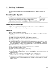
... documentation that occur at initial system startup are usually caused by incorrect installation or configuration. If applicable, ensure that there are using the system. Are the configuration settings made in their slots on the server board? ! Cold boot reset. Are the power supplies plugged in their ...correct? Check the AC cable on the Intel Customer Support website. 105 Are all peripheral devices installed correctly? ! Is AC power available at the AC source. ! Resetting the System To do this: Soft boot reset, which clears system memory and reloads the operating system. Is the...
... documentation that occur at initial system startup are usually caused by incorrect installation or configuration. If applicable, ensure that there are using the system. Are the configuration settings made in their slots on the server board? ! Cold boot reset. Are the power supplies plugged in their ...correct? Check the AC cable on the Intel Customer Support website. 105 Are all peripheral devices installed correctly? ! Is AC power available at the AC source. ! Resetting the System To do this: Soft boot reset, which clears system memory and reloads the operating system. Is the...
Product Guide
Page 126
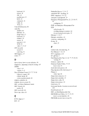
... USB, 10 VGA, 17 Console Redirection, 80 controller diskette, 64 Ethernet, 10 floppy disk, 13 keyboard, 13 memory, 12 mouse, 13 network, 9, 18 SCSI, 16 video, 9, 17, 67 CPU fan cable install, 45 removing, 51 CRT displays, 17 CSSU, 77 D device driver, how to create diskettes, 98 diagnostics, ... drive cable, 38 floppy write-protect, 10 form factor, 10 front panel header, location on server board, 120 Front Panel reset, 25 FRU, see Field Replaceable Unit FRU/SDR Load Utility, 22, 77, 79, 95 how to create diskettes, 98 FRU/SDR records, how to load, 96 Intel Server Board SE7501BR2 Product Guide
... USB, 10 VGA, 17 Console Redirection, 80 controller diskette, 64 Ethernet, 10 floppy disk, 13 keyboard, 13 memory, 12 mouse, 13 network, 9, 18 SCSI, 16 video, 9, 17, 67 CPU fan cable install, 45 removing, 51 CRT displays, 17 CSSU, 77 D device driver, how to create diskettes, 98 diagnostics, ... drive cable, 38 floppy write-protect, 10 form factor, 10 front panel header, location on server board, 120 Front Panel reset, 25 FRU, see Field Replaceable Unit FRU/SDR Load Utility, 22, 77, 79, 95 how to create diskettes, 98 FRU/SDR records, how to load, 96 Intel Server Board SE7501BR2 Product Guide
Product Guide
Page 127
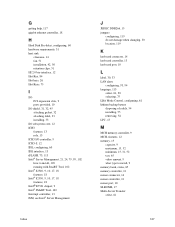
...interface, 13 iFLASH, 73, 113 Intel® Server Management, 21, 24, 79, 99, 102 how to install, 103 running with SmaRT Tool, 102 Intel® 82540, 9, 10, 17, 18 features, 18 Intel® 82550, 9, 10, 17, 18 features, 18 Intel® E7501 chipset, 9 Intel® SMaRT Tool, 102 Interrupt ...lithium backup battery disposing of safely, 54 installing, 55 removing, 54 LPC, 13 M MCH memory controller, 9 MCH, features, 12 memory, 15 capacity, 9 maximum, 15, 52 minimum, 15, 31, 52 test, 65 video amount, 9 what type to install, 9 memory bank, status, 65 memory controller, 12 mouse connector, 14 mouse...
...interface, 13 iFLASH, 73, 113 Intel® Server Management, 21, 24, 79, 99, 102 how to install, 103 running with SmaRT Tool, 102 Intel® 82540, 9, 10, 17, 18 features, 18 Intel® 82550, 9, 10, 17, 18 features, 18 Intel® E7501 chipset, 9 Intel® SMaRT Tool, 102 Interrupt ...lithium backup battery disposing of safely, 54 installing, 55 removing, 54 LPC, 13 M MCH memory controller, 9 MCH, features, 12 memory, 15 capacity, 9 maximum, 15, 52 minimum, 15, 31, 52 test, 65 video amount, 9 what type to install, 9 memory bank, status, 65 memory controller, 12 mouse connector, 14 mouse...

Product Guide
Page 130
sleep states, 20 SMaRT Tool, 102 how to install, 103 how to launch, 103 soft boot, 105 South Bridge, 9, 12 SSU,see System Setup Utility standoff, placement, 34 Super... 64 User binary, 113 User password, 84 configuring, 84 User Password on boot, 25 utility diskettes, how to create, 98 V VGA connector, 17 video, memory, 9 Video blanking, 67, 84 video controller, 9, 17, 67 video port, 9 video subsystem, 17 voltage regulator, 14 W Wake on LAN, 10, ... battery safely, 54 ESD can damage product, 30 hazardous electrical conditions, 29 WOL, see Wake on LAN18 130 Intel Server Board SE7501BR2 Product Guide
sleep states, 20 SMaRT Tool, 102 how to install, 103 how to launch, 103 soft boot, 105 South Bridge, 9, 12 SSU,see System Setup Utility standoff, placement, 34 Super... 64 User binary, 113 User password, 84 configuring, 84 User Password on boot, 25 utility diskettes, how to create, 98 V VGA connector, 17 video, memory, 9 Video blanking, 67, 84 video controller, 9, 17, 67 video port, 9 video subsystem, 17 voltage regulator, 14 W Wake on LAN, 10, ... battery safely, 54 ESD can damage product, 30 hazardous electrical conditions, 29 WOL, see Wake on LAN18 130 Intel Server Board SE7501BR2 Product Guide


