
Hardware User Guide
Page 15
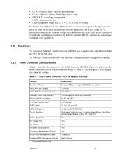
... Enclosures (SAF-TE), using an I2C interface to use RAID capabilities provided by the RAID Controller SRCS16 adapters in an enclosure containing your hard drives. 1.3 Hardware You can install the Intel® RAID Controller SRCS16 in a computer with the storage enclosure processor (SEP). ... logical drives allowed per controller • Up to Figure 3.1 for jumper and connector options. technology is supported • 64MB cache memory size • User-configurable stripe size of 2, 4, 8, 16, 32, 64, or 128KB In addition, the RAID Controller SRCS16 offers enclosure management through ...
... Enclosures (SAF-TE), using an I2C interface to use RAID capabilities provided by the RAID Controller SRCS16 adapters in an enclosure containing your hard drives. 1.3 Hardware You can install the Intel® RAID Controller SRCS16 in a computer with the storage enclosure processor (SEP). ... logical drives allowed per controller • Up to Figure 3.1 for jumper and connector options. technology is supported • 64MB cache memory size • User-configurable stripe size of 2, 4, 8, 16, 32, 64, or 128KB In addition, the RAID Controller SRCS16 offers enclosure management through ...
Hardware User Guide
Page 17
... the anti-static bag and inspect it for damage. Chapter 2 Hardware Installation This chapter describes the procedures for installing a RAID Controller SRCS16. The following items are required to install a Intel® RAID Controller SRCS16: • An Intel® RAID Controller SRCS16 and operating system driver • A host computer with an available 32- Chapter 3, "Intel® RAID Controller SRCS16 Technical Reference," provides the jumper definitions and locations.
... the anti-static bag and inspect it for damage. Chapter 2 Hardware Installation This chapter describes the procedures for installing a RAID Controller SRCS16. The following items are required to install a Intel® RAID Controller SRCS16: • An Intel® RAID Controller SRCS16 and operating system driver • A host computer with an available 32- Chapter 3, "Intel® RAID Controller SRCS16 Technical Reference," provides the jumper definitions and locations.
Hardware User Guide
Page 22
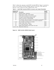
... (not used as the interface for factory use Default Setting Open Open Open Open Open Open Open Open Open Open - Figure 3.2 RAID Controller SRCS16 Board Layout Reserved [J17] 3.3V Load Sharing [J14] 167 mm Speaker [U6] Reserved [J16] Memory Modules (5) Battery Connector ... (dirty cache). Table 3-1 defines the connectors on the RAID Controller SRCS16. BIOS disabled) UART serial I/O connector for test (not present) Connector for details) Mode 0 Select (closed - Table 3-1 Intel® RAID Controller SRCS16 Connector and Jumper Description Jumpers and Connectors J1 J2 J3 J4 J5 J6 J7-J12 ...
... (not used as the interface for factory use Default Setting Open Open Open Open Open Open Open Open Open Open - Figure 3.2 RAID Controller SRCS16 Board Layout Reserved [J17] 3.3V Load Sharing [J14] 167 mm Speaker [U6] Reserved [J16] Memory Modules (5) Battery Connector ... (dirty cache). Table 3-1 defines the connectors on the RAID Controller SRCS16. BIOS disabled) UART serial I/O connector for test (not present) Connector for details) Mode 0 Select (closed - Table 3-1 Intel® RAID Controller SRCS16 Connector and Jumper Description Jumpers and Connectors J1 J2 J3 J4 J5 J6 J7-J12 ...