
User Manual
Page 2
... to become inoperable within a reasonable amount of our tools needs service or repair, please contact Technical Service by a 90 day limited warranty against manufacturers' defects. Parts; Light-Duty Air Tools 1 Year - Machine Accessories; Wilton branded products; Who is Covered This warranty covers any of an Authorized Service Center in your area call 1-800-274-6846 or use and are not binding. Please contact Technical...
... to become inoperable within a reasonable amount of our tools needs service or repair, please contact Technical Service by a 90 day limited warranty against manufacturers' defects. Parts; Light-Duty Air Tools 1 Year - Machine Accessories; Wilton branded products; Who is Covered This warranty covers any of an Authorized Service Center in your area call 1-800-274-6846 or use and are not binding. Please contact Technical...
User Manual
Page 3
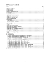
...Phase - Parts List 22 11.3.1 Model J-4400A Disc Sander Assembly - 2.0 Table of contents Section Page 1.0 Warranty and Service...2 2.0 Table of contents...3 3.0 Safety Warnings...4 4.0 Machine and Manual Overview ...6 5.0 Specifications ...7 6.0 Operating instructions ...8 6.1 Belt sander ...8 6.2 Adjusting the belt sander table ...8 6.3 Using the indexing lock handle...8 6.4 Adjusting the belt sander arm...8 6.5 Adjusting disc sander table ...9 6.6 Use of the Miter Gauge ...9 7.0 Maintenance...10 7.1 Belt replacement ...10 7.2 Track mechanism maintenance ...10 7.3 Installing abrasive...
...Phase - Parts List 22 11.3.1 Model J-4400A Disc Sander Assembly - 2.0 Table of contents Section Page 1.0 Warranty and Service...2 2.0 Table of contents...3 3.0 Safety Warnings...4 4.0 Machine and Manual Overview ...6 5.0 Specifications ...7 6.0 Operating instructions ...8 6.1 Belt sander ...8 6.2 Adjusting the belt sander table ...8 6.3 Using the indexing lock handle...8 6.4 Adjusting the belt sander arm...8 6.5 Adjusting disc sander table ...9 6.6 Use of the Miter Gauge ...9 7.0 Maintenance...10 7.1 Belt replacement ...10 7.2 Track mechanism maintenance ...10 7.3 Installing abrasive...
User Manual
Page 4
... work . Never brush chips away while the machine is securely anchored to fall into the machine or cause your hands and it was shipped with ANSI Z87.1 specifications could result in operation. 14. Remove adjusting keys and wrenches before servicing, whenever changing accessories or when general maintenance is any machine used . 9. Never leave the machine running while unattended. Always follow the instructions in design and safety...
... work . Never brush chips away while the machine is securely anchored to fall into the machine or cause your hands and it was shipped with ANSI Z87.1 specifications could result in operation. 14. Remove adjusting keys and wrenches before servicing, whenever changing accessories or when general maintenance is any machine used . 9. Never leave the machine running while unattended. Always follow the instructions in design and safety...

User Manual
Page 5
... the face of the workpiece off by removing starter keys. 20. Safety shoes which shows backing, nicks or cuts on sanding and handling. 5. Make your workshop completely safe by using ; Wire Sizes Caution: For circuits that wears down to the motor. Sanding sparks, chips and dust particles thrown off the wheel. 11. Always wear protective eyewear when operating machinery. Abrasive discs must be certain...
... the face of the workpiece off by removing starter keys. 20. Safety shoes which shows backing, nicks or cuts on sanding and handling. 5. Make your workshop completely safe by using ; Wire Sizes Caution: For circuits that wears down to the motor. Sanding sparks, chips and dust particles thrown off the wheel. 11. Always wear protective eyewear when operating machinery. Abrasive discs must be certain...
User Manual
Page 6
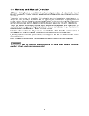
...JET can bypass those instructions which the machine is used will help you . 4.0 Machine and Manual Overview JET Abrasive Finishing Machines are questions or comments, please contact your choice of electrical systems available for these systems are typically considered sanding...speed of stock removal and the quality of the abrasive disc or belt mounted on the machine. With very fine grits, these machines are using one of environment in this manual will often be reached at our web site: www.jettools.com. however, local codes and the type of the Model J-4200A Series Belt...
...JET can bypass those instructions which the machine is used will help you . 4.0 Machine and Manual Overview JET Abrasive Finishing Machines are questions or comments, please contact your choice of electrical systems available for these systems are typically considered sanding...speed of stock removal and the quality of the abrasive disc or belt mounted on the machine. With very fine grits, these machines are using one of environment in this manual will often be reached at our web site: www.jettools.com. however, local codes and the type of the Model J-4200A Series Belt...
User Manual
Page 7
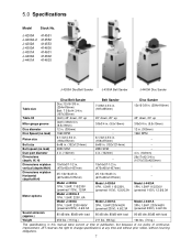
... continuous improvement, JET reserves the right to change specifications at any time and without prior notice, without incurring obligations. 7 J-4200A J-4200A-2 J-4202A J-4300A J-4301A J-4400A J-4401A 414551 414552 414553 414600 414601 414602 414603 J-4200A Disc/Belt Sander J-4300A Belt Sander J-4400A Disc Sander Table size Table tilt Miter gauge groove Disc diameter Disc Speed (no load) Platen size Belt size Belt speed (no load) Dust port diameter Dimensions (depth, W, H) Dimensions w/platen vertical (depthxWxH) Dimensions w/platen Horizontal (depthxWxH) Motor options Sound...
... continuous improvement, JET reserves the right to change specifications at any time and without prior notice, without incurring obligations. 7 J-4200A J-4200A-2 J-4202A J-4300A J-4301A J-4400A J-4401A 414551 414552 414553 414600 414601 414602 414603 J-4200A Disc/Belt Sander J-4300A Belt Sander J-4400A Disc Sander Table size Table tilt Miter gauge groove Disc diameter Disc Speed (no load) Platen size Belt size Belt speed (no load) Dust port diameter Dimensions (depth, W, H) Dimensions w/platen vertical (depthxWxH) Dimensions w/platen Horizontal (depthxWxH) Motor options Sound...

User Manual
Page 8
... instructions on safe machine usage on Track Mechanism Maintenance if you require. 3. Lock the table lock handle. Always turn the motor off the motor before adjusting the arm angle. To adjust to the machines and not the type of machinable materials. Unlock both lock bolts, and replace arbor cover. When removing stock from a wide variety of abrasive finishing being performed. Never adjust the arm angle while the sander is used to lock...
... instructions on safe machine usage on Track Mechanism Maintenance if you require. 3. Lock the table lock handle. Always turn the motor off the motor before adjusting the arm angle. To adjust to the machines and not the type of machinable materials. Unlock both lock bolts, and replace arbor cover. When removing stock from a wide variety of abrasive finishing being performed. Never adjust the arm angle while the sander is used to lock...

User Manual
Page 9
... be removed or left in position, and may also be used on either the disc or belt surfaces to sand accurate angles on the miter gauge. 2. Lock the two locking knobs underneath the table. 6.6 Use of the Miter Gauge The miter gauge can be set to any angle to the required angle. 3. However, by sanding a piece of various angles. The basic method is running. Unlock both lock bolts and replace arbor cover. 6.5 Adjusting disc sander table Never adjust the table angle...
... be removed or left in position, and may also be used on either the disc or belt surfaces to sand accurate angles on the miter gauge. 2. Lock the two locking knobs underneath the table. 6.6 Use of the Miter Gauge The miter gauge can be set to any angle to the required angle. 3. However, by sanding a piece of various angles. The basic method is running. Unlock both lock bolts and replace arbor cover. 6.5 Adjusting disc sander table Never adjust the table angle...
User Manual
Page 10
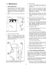
.... 12.5. Turn the drums by tightening or replacing any loose condition by hand to the machine and return it . Always check the tracking when replacing a belt. 12. Loosen the tracking lock knob. 12.3. Jog the motor on and leave it according to prevent accidental start-ups. As mentioned in the preceding section, the need for removal and replacement of the belt in adjusting the tension...
.... 12.5. Turn the drums by tightening or replacing any loose condition by hand to the machine and return it . Always check the tracking when replacing a belt. 12. Loosen the tracking lock knob. 12.3. Jog the motor on and leave it according to prevent accidental start-ups. As mentioned in the preceding section, the need for removal and replacement of the belt in adjusting the tension...

User Manual
Page 11
... the drive disc. (See Figure 8.) 6. This allows you to prevent accidental start -ups. 2. Position the new disc carefully so it is made. 7. Figure 10: Disc table lock knob 5. Reconnect the power to the Belt replacement instructions. 7.3 Installing abrasive discs 1. Remove the belt guard (Figure 9) and disc table. 3. Loosen the four motor bolts so the motor can slide on its plate. built up material in the upper part of the base mounting...
... the drive disc. (See Figure 8.) 6. This allows you to prevent accidental start -ups. 2. Position the new disc carefully so it is made. 7. Figure 10: Disc table lock knob 5. Reconnect the power to the Belt replacement instructions. 7.3 Installing abrasive discs 1. Remove the belt guard (Figure 9) and disc table. 3. Loosen the four motor bolts so the motor can slide on its plate. built up material in the upper part of the base mounting...
User Manual
Page 13
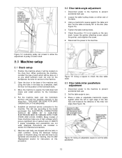
... used. Disconnect power to the machine to the machine. 2. Loosen the table locking knobs on this procedure. When positioning the machine, consider the type of work which pose a significant risk of pulley on arbor shaft. 8.0 Machine setup 8.1 Basic setup 1. THIS MUST BE DONE FOR SAFE OPERATION OF THE MACHINE. 5. Place a scale or adjustable machinist's square against the table and disc, set the table parallelism. 13 Tighten the table locking knobs...
... used. Disconnect power to the machine to the machine. 2. Loosen the table locking knobs on this procedure. When positioning the machine, consider the type of work which pose a significant risk of pulley on arbor shaft. 8.0 Machine setup 8.1 Basic setup 1. THIS MUST BE DONE FOR SAFE OPERATION OF THE MACHINE. 5. Place a scale or adjustable machinist's square against the table and disc, set the table parallelism. 13 Tighten the table locking knobs...

User Manual
Page 14
... platen. 6. Set the table angle to 3/32 inch. Reconnect the electrical power to about 15°. 2. Figure 17: Table attachment screws - Loosen the table locking handle and tilt the table upward to the machine. Disconnect the electrical power to the miter slot. 5. If it is on the belt table. 8.6 Belt table angle adjustment 1. DO NOT reset the pointer after this operation. 14 Move the measuring device to the opposite edge of the belt or platen...
... platen. 6. Set the table angle to 3/32 inch. Reconnect the electrical power to about 15°. 2. Figure 17: Table attachment screws - Loosen the table locking handle and tilt the table upward to the machine. Disconnect the electrical power to the miter slot. 5. If it is on the belt table. 8.6 Belt table angle adjustment 1. DO NOT reset the pointer after this operation. 14 Move the measuring device to the opposite edge of the belt or platen...

User Manual
Page 15
... the drive and idler drums. 7. Reconnect the electrical power to instructions in this manual. 12. Remove the table by unscrewing the locking handling and lifting the complete table assembly, from the machine. 4. Disconnect the electrical power to the machine to table adjustment instructions in section 7.1, Belt replacement. 10. If you should be certain: 1. HOWEVER, before shipment and the power cord is 1/32 inch higher than the full load current of the motor. The service...
... the drive and idler drums. 7. Reconnect the electrical power to instructions in this manual. 12. Remove the table by unscrewing the locking handling and lifting the complete table assembly, from the machine. 4. Disconnect the electrical power to the machine to table adjustment instructions in section 7.1, Belt replacement. 10. If you should be certain: 1. HOWEVER, before shipment and the power cord is 1/32 inch higher than the full load current of the motor. The service...

User Manual
Page 16
... cable wires to the motor connection diagram in your specific manufacturing operation. 9.1 Single phase electrical hookup When connecting your dealer or contact JET to the service branch using a hardwired junction box connection. The motor should now be considered wired correctly. Remove terminal cover from the motor. All electrical service work on your JET sander should be performed by a qualified, licensed electrician who is familiar with the 460V switch (p/n 4202A...
... cable wires to the motor connection diagram in your specific manufacturing operation. 9.1 Single phase electrical hookup When connecting your dealer or contact JET to the service branch using a hardwired junction box connection. The motor should now be considered wired correctly. Remove terminal cover from the motor. All electrical service work on your JET sander should be performed by a qualified, licensed electrician who is familiar with the 460V switch (p/n 4202A...

User Manual
Page 17
... machines on the branch to do the cutting. Inspect all circuit tracing, diagnosis and repair. 17 Motor stalls easily Low voltage. Replace the blown fuse. Belt is more taut. Slack in the above table JET recommends the use of the electrical faults and corrections in the abrasive belt Remove the belt and put a straight edge along the drive roller. There should be certain someone...
... machines on the branch to do the cutting. Inspect all circuit tracing, diagnosis and repair. 17 Motor stalls easily Low voltage. Replace the blown fuse. Belt is more taut. Slack in the above table JET recommends the use of the electrical faults and corrections in the abrasive belt Remove the belt and put a straight edge along the drive roller. There should be certain someone...
User Manual
Page 19
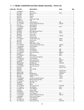
Parts List Index No Part No Description Size Qty 1 J-5508427 Bracket...1 2 5511833 Square Nut M10 1 3 5051081 Spring ...1 4 5051091 Sleeve...1 5 5051131 Collar ...1 6 5508431 Shaft with Collar 1 7 J-5051151 Cap ...1 8 TS-2361051 Lock Washer M5 2 9 TS-1513051 Socket Head Flat Screw M5x25 2 10 5051721 Hand Wheel 1 12 TS-1550071 Flat Washer M10 2 13 J-5508432 Tilting Table 1 14 5508450 Hand Knob...4 15 5508429 Belt Adjustment Knob M10 1 16 5511824 Drive Screw 2x5 5 17 5508437 Stop Lock...1 18 5511828 Groove...
Parts List Index No Part No Description Size Qty 1 J-5508427 Bracket...1 2 5511833 Square Nut M10 1 3 5051081 Spring ...1 4 5051091 Sleeve...1 5 5051131 Collar ...1 6 5508431 Shaft with Collar 1 7 J-5051151 Cap ...1 8 TS-2361051 Lock Washer M5 2 9 TS-1513051 Socket Head Flat Screw M5x25 2 10 5051721 Hand Wheel 1 12 TS-1550071 Flat Washer M10 2 13 J-5508432 Tilting Table 1 14 5508450 Hand Knob...4 15 5508429 Belt Adjustment Knob M10 1 16 5511824 Drive Screw 2x5 5 17 5508437 Stop Lock...1 18 5511828 Groove...

User Manual
Page 22
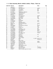
Parts List Index No Part No Description Size Qty 1 J-5508427 Bracket...1 2 5511833 Square Nut M10 1 3 5051081 Spring ...1 4 5051091 Sleeve...1 5 5051131 Collar ...1 6 5508431 Shaft with Collar 1 7 J-5051151 Cap ...1 8 TS-2361051 Lock Washer M5 2 9 TS-1513051 Socket Head Flat Screw M5x25 2 10 5051721 Hand Wheel 1 12 TS-1550071 Flat Washer M10 1 13 J-5508432 Tilting Table 1 14 5508450 Hand Knob...2 15 5508429 Belt Adj. 11.2.2 Model J-4300A Belt Sander Assembly - Knob M10 1 16 5511824 Drive Screw 2x5 3 17 5508437...
Parts List Index No Part No Description Size Qty 1 J-5508427 Bracket...1 2 5511833 Square Nut M10 1 3 5051081 Spring ...1 4 5051091 Sleeve...1 5 5051131 Collar ...1 6 5508431 Shaft with Collar 1 7 J-5051151 Cap ...1 8 TS-2361051 Lock Washer M5 2 9 TS-1513051 Socket Head Flat Screw M5x25 2 10 5051721 Hand Wheel 1 12 TS-1550071 Flat Washer M10 1 13 J-5508432 Tilting Table 1 14 5508450 Hand Knob...2 15 5508429 Belt Adj. 11.2.2 Model J-4300A Belt Sander Assembly - Knob M10 1 16 5511824 Drive Screw 2x5 3 17 5508437...
User Manual
Page 25
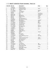
... Sander Assembly - Parts List Index No Part No Description Size Qty 1 J-5508438 Bearing Housing 1 2 TS-1523011 Socket Set Screw M6x6 2 3 5511725 4200 Arbor Pulley 1 4 TS-1504061 SHCS M8x30 4 5 TS-2361081 Lock Washer M8 4 6 5508443 Drive Shaft...1 7 5051451 Key 5x5x35 mm 1 8 4200A-042 Key 5x5x55 mm 1 9 BB-6204ZZ Ball Bearing 6204ZZ 1 10 5051471 Retaining Ring S20 1 11 VB-A59 V-Belt 17610 1 12 5511818 Flat Head Screw M5x6 4 13 J-5508444 Belt Guard Assembly...
... Sander Assembly - Parts List Index No Part No Description Size Qty 1 J-5508438 Bearing Housing 1 2 TS-1523011 Socket Set Screw M6x6 2 3 5511725 4200 Arbor Pulley 1 4 TS-1504061 SHCS M8x30 4 5 TS-2361081 Lock Washer M8 4 6 5508443 Drive Shaft...1 7 5051451 Key 5x5x35 mm 1 8 4200A-042 Key 5x5x55 mm 1 9 BB-6204ZZ Ball Bearing 6204ZZ 1 10 5051471 Retaining Ring S20 1 11 VB-A59 V-Belt 17610 1 12 5511818 Flat Head Screw M5x6 4 13 J-5508444 Belt Guard Assembly...
User Manual
Page 27
... Pan Head Screw M5x16 1 29 4200A-B330 Cord Clamp...1 30 TS-1540031 Hex Nut M5 1 31 4200A-B332 Wiring Nut ...2 32 TS-1550021 Flat Washer M4 6 33 4200A-B334 Label - 11.4.2 Base Assembly: Model J-4300A, 1 Phase - Voltage 1 34 J-5514650 Motor 1-1/2HP 115/230V 1Ph 1 35 5512937 Key 5x5x35 mm 1 36 4200A-436 Motor Pulley 1 37 TS-1523011 Socket Set Screw M6x6 1 38 TS-1533042 Pan Head Screw M5X12 2 39 4200A-439 Strain Relief Plate...
... Pan Head Screw M5x16 1 29 4200A-B330 Cord Clamp...1 30 TS-1540031 Hex Nut M5 1 31 4200A-B332 Wiring Nut ...2 32 TS-1550021 Flat Washer M4 6 33 4200A-B334 Label - 11.4.2 Base Assembly: Model J-4300A, 1 Phase - Voltage 1 34 J-5514650 Motor 1-1/2HP 115/230V 1Ph 1 35 5512937 Key 5x5x35 mm 1 36 4200A-436 Motor Pulley 1 37 TS-1523011 Socket Set Screw M6x6 1 38 TS-1533042 Pan Head Screw M5X12 2 39 4200A-439 Strain Relief Plate...
User Manual
Page 31
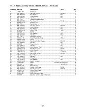
... 115/230V 1Ph 1 35 5512937 Key 5x5x35 mm 1 36 4200A-436 Motor Pulley 1 37 TS-1523011 Socket Set Screw M6x6 1 38 TS-1533042 Pan Head Screw M5X12 2 39 4200A-439 Strain Relief Plate 1 40 J-5511729 Large Cover 1 41 J-5052431 Motor Mounting Plate 1 42 605415 Inlet Adaptor 2 1 43 605417 Wire Hose Clamp 2"(53mm 2 44 HS240007 Aluminum Hose 2"x714mm 1 9145531 Machine Safety Label (not shown 1 31 11.6.2 Base Assembly: Model J-4200A & 4400A, 1 Phase -
... 115/230V 1Ph 1 35 5512937 Key 5x5x35 mm 1 36 4200A-436 Motor Pulley 1 37 TS-1523011 Socket Set Screw M6x6 1 38 TS-1533042 Pan Head Screw M5X12 2 39 4200A-439 Strain Relief Plate 1 40 J-5511729 Large Cover 1 41 J-5052431 Motor Mounting Plate 1 42 605415 Inlet Adaptor 2 1 43 605417 Wire Hose Clamp 2"(53mm 2 44 HS240007 Aluminum Hose 2"x714mm 1 9145531 Machine Safety Label (not shown 1 31 11.6.2 Base Assembly: Model J-4200A & 4400A, 1 Phase -


