
User Manual
Page 4
...hoist to lift or support loads over sharp edges. All pulls or lifts must have been obtained. 6. Do not place yourself or other object. 10. Never use until it has been repaired or replaced. 12. Replace warning labels if they become obscured or removed. 4. Do not use this ...damage prior to comply with the proper and safe operation of the equipment. If used in an unsafe position. 18. Do not attempt to a qualified JET service center. 20. This standard is twisted, kinked or damaged. 16. If in service. 23. Read and understand any other such device. 9. Replace...
...hoist to lift or support loads over sharp edges. All pulls or lifts must have been obtained. 6. Do not place yourself or other object. 10. Never use until it has been repaired or replaced. 12. Replace warning labels if they become obscured or removed. 4. Do not use this ...damage prior to comply with the proper and safe operation of the equipment. If used in an unsafe position. 18. Do not attempt to a qualified JET service center. 20. This standard is twisted, kinked or damaged. 16. If in service. 23. Read and understand any other such device. 9. Replace...
User Manual
Page 6
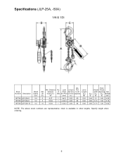
...hooks (in.) falls Ø x Pitch of lever capacity (in.) (ft.) "A" (mm) (in.) "B" 5 8.27 1 4x12 3.02 60 5.91 5 10.04 1 4.3x12 2.83 86 8.46 10 10.04 1 4.3x12 2.83 86 8.46 Hook Overall Throat width Opening Net (in.) (in.) (in other lengths. Specify length when ordering. 6 Load Lift per... Weight "C" "D" "E" (lbs) 2.44 3.1 1.40 4.56 2.68 3.74 1.38 5.18 2.68 3.74 1.38 6.82 NOTE: The above stock numbers are representative; Specifications (JLP-25A, -50A) Stock Number Description 187740 JLP-25A-5 187505 JLP-50A-5 187506 JLP-50A-10 Rated Capcty. (ton) 1/4 1/2 1/2 Lbs. Min.
...hooks (in.) falls Ø x Pitch of lever capacity (in.) (ft.) "A" (mm) (in.) "B" 5 8.27 1 4x12 3.02 60 5.91 5 10.04 1 4.3x12 2.83 86 8.46 10 10.04 1 4.3x12 2.83 86 8.46 Hook Overall Throat width Opening Net (in.) (in.) (in other lengths. Specify length when ordering. 6 Load Lift per... Weight "C" "D" "E" (lbs) 2.44 3.1 1.40 4.56 2.68 3.74 1.38 5.18 2.68 3.74 1.38 6.82 NOTE: The above stock numbers are representative; Specifications (JLP-25A, -50A) Stock Number Description 187740 JLP-25A-5 187505 JLP-50A-5 187506 JLP-50A-10 Rated Capcty. (ton) 1/4 1/2 1/2 Lbs. Min.

User Manual
Page 7
... to Lift Length falls Ø x Pitch of lever capacity (in.) (mm) (in.) "B" 3/4 5 12.79 1 6x18 0.81 31 11.02 3/4 10 12.79 1 6x18 0.81 31 11.02 3/4 15 12.79 1 6x18 0.81 31 11.02 3/4 20 12.79 1 6x18 0.81 31 11.02 ...JLP-75A, -150A, -300A, -600A) Stock Number Description 187606 JLP-75A-5 187607 JLP-75A-10 187608 JLP-75A-15 187609 JLP-75A-20 287606 JLP-75AWO-5 * 187610 JLP-150A-5 187611 JLP-150A-10 187612 JLP-150A-15 187613 JLP-150A-20 287610 JLP-150AWO-5 * 187614 JLP-300A-5 187615 JLP-300A-10 187616 JLP-300A-15 187617 JLP-300A-20 287614 JLP-300AWO-5 * 187618 JLP-600A-5 187621 JLP...
... to Lift Length falls Ø x Pitch of lever capacity (in.) (mm) (in.) "B" 3/4 5 12.79 1 6x18 0.81 31 11.02 3/4 10 12.79 1 6x18 0.81 31 11.02 3/4 15 12.79 1 6x18 0.81 31 11.02 3/4 20 12.79 1 6x18 0.81 31 11.02 ...JLP-75A, -150A, -300A, -600A) Stock Number Description 187606 JLP-75A-5 187607 JLP-75A-10 187608 JLP-75A-15 187609 JLP-75A-20 287606 JLP-75AWO-5 * 187610 JLP-150A-5 187611 JLP-150A-10 187612 JLP-150A-15 187613 JLP-150A-20 287610 JLP-150AWO-5 * 187614 JLP-300A-5 187615 JLP-300A-10 187616 JLP-300A-15 187617 JLP-300A-20 287614 JLP-300AWO-5 * 187618 JLP-600A-5 187621 JLP...

User Manual
Page 9
... the lever in the up position, check free play has reached 3/4 of the hook reaches 10° (see Figure 3). • Chemical corrosion or cracks on the hook. • Excessive wear on the chain or with your JET lever hoist is designed, manufactured, and tested for proper fit and durability. Use of other... 1. Never allow oil to check top and bottom hooks for proper opening .) Do not attempt repair of the hook. have it inspected and repaired by a JET authorized service center. 3.
... the lever in the up position, check free play has reached 3/4 of the hook reaches 10° (see Figure 3). • Chemical corrosion or cracks on the hook. • Excessive wear on the chain or with your JET lever hoist is designed, manufactured, and tested for proper fit and durability. Use of other... 1. Never allow oil to check top and bottom hooks for proper opening .) Do not attempt repair of the hook. have it inspected and repaired by a JET authorized service center. 3.

User Manual
Page 10
Operation The JLP Lever Hoist may be lifted. This will allow free-wheel mode. (NOTE: Chain will only free-wheel when there is the general procedure for operating ...; Never load the hook tip (B, Figure 5). • Never load the hook off the centerline (C, Figure 5). • Never load the hook sideways (D, Figure 5). 3. Figure 4 Figure 5 Figure 6 10 Ratchet the lever to the DOWN position and ratchet the handle. Place the selector switch on the bottom hook (Figure 4). Move selector switch to both...
Operation The JLP Lever Hoist may be lifted. This will allow free-wheel mode. (NOTE: Chain will only free-wheel when there is the general procedure for operating ...; Never load the hook tip (B, Figure 5). • Never load the hook off the centerline (C, Figure 5). • Never load the hook sideways (D, Figure 5). 3. Figure 4 Figure 5 Figure 6 10 Ratchet the lever to the DOWN position and ratchet the handle. Place the selector switch on the bottom hook (Figure 4). Move selector switch to both...

User Manual
Page 11
These will spring back away from dragging over sharp edges or corners. Figure 7 Figure 8 Figure 9 Figure 10 Figure 11 11 Do not put one end on the inside of the safety latch before pulling or lifting the load. Do not use an ..., (Fig. 9). ‰ When using a wire rope sling, the puller must be applied along a straight line parallel to the surface on which it is resting (Fig. 10). ‰ When lifting loads, hook the load with slings. Do not use a foot to apply pressure to the lever (B, Fig. 8). ‰ Prevent the chain from...
These will spring back away from dragging over sharp edges or corners. Figure 7 Figure 8 Figure 9 Figure 10 Figure 11 11 Do not put one end on the inside of the safety latch before pulling or lifting the load. Do not use an ..., (Fig. 9). ‰ When using a wire rope sling, the puller must be applied along a straight line parallel to the surface on which it is resting (Fig. 10). ‰ When lifting loads, hook the load with slings. Do not use a foot to apply pressure to the lever (B, Fig. 8). ‰ Prevent the chain from...

User Manual
Page 13
Figure 15 shows the proper orientation of the timing marks when meshing the gears. Figure 15 13 Brake Disc Wear Limits Figure 14 Capacity 0.25 t 0.5 t 0.75 t 1.5 t 3 t 6 t D (in) 1.38 1.89 2.13 2.56 2.56 2.56 d = Inner diameter D = Outer diameter tn = Normal measurement tv = Replacement limit d (in) 0.87 1.00 1.34 1.59 1.59 1.59 tn (in) 0.14 0.12 0.14 0.14 0.14 0.14 tv(in) 0.12 0.10 0.12 0.12 0.12 0.12 Timing Marks for Gear Replacement If the gears on the JLP-A hoist need replacement or removal for any reason, make sure they are re-installed correctly.
Figure 15 shows the proper orientation of the timing marks when meshing the gears. Figure 15 13 Brake Disc Wear Limits Figure 14 Capacity 0.25 t 0.5 t 0.75 t 1.5 t 3 t 6 t D (in) 1.38 1.89 2.13 2.56 2.56 2.56 d = Inner diameter D = Outer diameter tn = Normal measurement tv = Replacement limit d (in) 0.87 1.00 1.34 1.59 1.59 1.59 tn (in) 0.14 0.12 0.14 0.14 0.14 0.14 tv(in) 0.12 0.10 0.12 0.12 0.12 0.12 Timing Marks for Gear Replacement If the gears on the JLP-A hoist need replacement or removal for any reason, make sure they are re-installed correctly.

User Manual
Page 15
... 7 mm 1 Spring ...1 Roller 5 mm 1 6 JLP25A-06 Bolt with Nut M3.5 1 7 JLP25A-07 Rubber Grip 1 8 JLP25A-08 Change Over Gear 1 9 JLP25A-09 Lever Handle Bushing 1 10 JLP25A-10 Nut and Spring Washer M5 and 5 mm 2 11 JLP25A-11 Hex Screw Nut and Spring Washer M4x4 mm 1 12 JLP25A-12 Brake Cover 1 13 JLP25A... JLP25A-37 Chain Stop ...1 When ordering replacement chain (#36), specify length. 15 Parts List Index No. M5x12 and Ø5 mm 1 36 JLP25A-36 Load Chain - JLP-25A - Part No.
... 7 mm 1 Spring ...1 Roller 5 mm 1 6 JLP25A-06 Bolt with Nut M3.5 1 7 JLP25A-07 Rubber Grip 1 8 JLP25A-08 Change Over Gear 1 9 JLP25A-09 Lever Handle Bushing 1 10 JLP25A-10 Nut and Spring Washer M5 and 5 mm 2 11 JLP25A-11 Hex Screw Nut and Spring Washer M4x4 mm 1 12 JLP25A-12 Brake Cover 1 13 JLP25A... JLP25A-37 Chain Stop ...1 When ordering replacement chain (#36), specify length. 15 Parts List Index No. M5x12 and Ø5 mm 1 36 JLP25A-36 Load Chain - JLP-25A - Part No.

User Manual
Page 17
... 1 37 JLP25A-37 Chain Stop ...1 When ordering replacement chain (#36), specify length. 17 M6x10 and Ø6 mm 1 36 JLP50A-36 Load Chain - JLP-50A - Description Size Qty 1 JLP25A-01 Snap Ring 7 mm 1 2 JLP25A-02 Handwheel...1 3 JLP50A-03 Stop Knob ...1 4 JLP50A-04 Snap Ring 28 mm... 6 JLP25A-06 Bolt with Nut M3.5 1 7 JLP50A-07 Rubber Grip 1 8 JLP50A-08 Change Over Gear 1 9 JLP50A-09 Lever Handle Bushing 1 10 JLP50A-10 Nut and Spring Washer M6 and 6 mm 2 11 JLP25A-11 Hex Screw Nut and Spring Washer M4x4 mm 1 12 JLP50A-12 Brake Cover 1 13 JLP50A...
... 1 37 JLP25A-37 Chain Stop ...1 When ordering replacement chain (#36), specify length. 17 M6x10 and Ø6 mm 1 36 JLP50A-36 Load Chain - JLP-50A - Description Size Qty 1 JLP25A-01 Snap Ring 7 mm 1 2 JLP25A-02 Handwheel...1 3 JLP50A-03 Stop Knob ...1 4 JLP50A-04 Snap Ring 28 mm... 6 JLP25A-06 Bolt with Nut M3.5 1 7 JLP50A-07 Rubber Grip 1 8 JLP50A-08 Change Over Gear 1 9 JLP50A-09 Lever Handle Bushing 1 10 JLP50A-10 Nut and Spring Washer M6 and 6 mm 2 11 JLP25A-11 Hex Screw Nut and Spring Washer M4x4 mm 1 12 JLP50A-12 Brake Cover 1 13 JLP50A...