
Instructions
Page 2
... by JVC could void the warranty. • When you don't use this TV set for your safety. • To prevent electric shock do not use this polarized plug with arrowhead symbol, within an equilateral triangle is intended to alert the user to the presence of electric shock to environmental considerations. Do not remove cover (or back). No user serviceable parts inside...
... by JVC could void the warranty. • When you don't use this TV set for your safety. • To prevent electric shock do not use this polarized plug with arrowhead symbol, within an equilateral triangle is intended to alert the user to the presence of electric shock to environmental considerations. Do not remove cover (or back). No user serviceable parts inside...

Instructions
Page 4
... objects into such power lines or circuits. Do not use a mounting kit approved by the TV set manufacturer. - Wall or shelf mounting should follow the manufacturer's instructions, and should use liquid or an aerosol cleaner. 12 Never add accessories to be released. EXAMPLE OF ANTENNA GROUNDING AS PER NATIONAL ELECTRICAL CODE GROUND CLAMP ANTENNA LEAD IN WIRE ELECTRICAL SERVICE EQUIPMENT NEC - Never...
... objects into such power lines or circuits. Do not use a mounting kit approved by the TV set manufacturer. - Wall or shelf mounting should follow the manufacturer's instructions, and should use liquid or an aerosol cleaner. 12 Never add accessories to be released. EXAMPLE OF ANTENNA GROUNDING AS PER NATIONAL ELECTRICAL CODE GROUND CLAMP ANTENNA LEAD IN WIRE ELECTRICAL SERVICE EQUIPMENT NEC - Never...

Instructions
Page 5
... replacement parts he uses have the service technician verify in any service or repairs to this TV set , please ask the service technician to be left unattended for an extended period of cable entry as practical. this TV set yourself as improper adjustment of other controls may result in particular, specifies that provides guidelines for service. 16 Do not attempt to service this indicates a need...
... replacement parts he uses have the service technician verify in any service or repairs to this TV set , please ask the service technician to be left unattended for an extended period of cable entry as practical. this TV set yourself as improper adjustment of other controls may result in particular, specifies that provides guidelines for service. 16 Do not attempt to service this indicates a need...
Instructions
Page 7
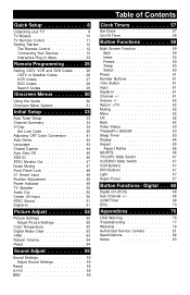
... 60 Swap 60 Select 60 Power 61 Number Buttons 61 100+ Button 61 Input 61 Digital-In 61 Channel 61 Volume 62 Return +/TV 62 Muting 62 Menu 62 OK 62 Back 62 Video Status 63 TheaterPro D6500K 63 Sleep Timer 63 Display 64 Aspect 65 Aspect Ratios 66 ML/MTS 66 TV/CATV Slide Switch 67 VCR/DVD Slide Switch 67 VCR Buttons 67 DVD Buttons 67 Light 67 Super Focus 67 Button Functions - Digital . . . 68 Digital CH (DCS...
... 60 Swap 60 Select 60 Power 61 Number Buttons 61 100+ Button 61 Input 61 Digital-In 61 Channel 61 Volume 62 Return +/TV 62 Muting 62 Menu 62 OK 62 Back 62 Video Status 63 TheaterPro D6500K 63 Sleep Timer 63 Display 64 Aspect 65 Aspect Ratios 66 ML/MTS 66 TV/CATV Slide Switch 67 VCR/DVD Slide Switch 67 VCR Buttons 67 DVD Buttons 67 Light 67 Super Focus 67 Button Functions - Digital . . . 68 Digital CH (DCS...

Instructions
Page 10
... Models NOTE: Before you in the service manual before plugging the TV's power cord into an AC outlet. Rear Panel Diagram MODELS: AV-65WP94 AV-56WP94 SERVICE PORT FOR SERVICE PERSON SPEAKER INPUT 16Ω 60 W MAX OPTICAL OUT DIGITAL AUDIO 75Ω (VHF/UHF) ATSC IN i.LINK IN OUT S400(TS) UNPLUG THE POWER CORD FROM AC OUTLET BEFORE REMOVING THE REAR COVER When the rear cover is a registered trademark of the television...
... Models NOTE: Before you in the service manual before plugging the TV's power cord into an AC outlet. Rear Panel Diagram MODELS: AV-65WP94 AV-56WP94 SERVICE PORT FOR SERVICE PERSON SPEAKER INPUT 16Ω 60 W MAX OPTICAL OUT DIGITAL AUDIO 75Ω (VHF/UHF) ATSC IN i.LINK IN OUT S400(TS) UNPLUG THE POWER CORD FROM AC OUTLET BEFORE REMOVING THE REAR COVER When the rear cover is a registered trademark of the television...
Instructions
Page 13
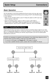
... finished connecting your remote control to determine which connection setup is not necessary for you use a Cable TV Box? Move the switch to TV. Connecting Your Devices LTI SCREEN Please follow these diagrams and the television does not work properly, contact your local cable operator. • To connect a DVD player, see pages 26 to 29 for instructions on programming your devices, plug the power cord into the nearest power outlet and turn on the TV. A VCR is...
... finished connecting your remote control to determine which connection setup is not necessary for you use a Cable TV Box? Move the switch to TV. Connecting Your Devices LTI SCREEN Please follow these diagrams and the television does not work properly, contact your local cable operator. • To connect a DVD player, see pages 26 to 29 for instructions on programming your devices, plug the power cord into the nearest power outlet and turn on the TV. A VCR is...

Instructions
Page 15
... button or do not operate ATSC MONITOR OUT in the Initial Setup Menu while recording. Connect it to view premium cable channels. • When you play the limited recording program or the limited copied media, ATSC OUTPUT does not output anything. • If you press or operate it will have only one audio out jack. Quick Setup Connections Diagram #2 AUDIO R L INPUT 3 VIDEO ATSC OUTPUT S VIDEO OVER VIDEO INPUT 2 INPUT 1 AV COMPULINK OVER L AUDIO R TV Rear Panel 75 Ω (VHF / UHF) Cable or Antenna Output...
... button or do not operate ATSC MONITOR OUT in the Initial Setup Menu while recording. Connect it to view premium cable channels. • When you play the limited recording program or the limited copied media, ATSC OUTPUT does not output anything. • If you press or operate it will have only one audio out jack. Quick Setup Connections Diagram #2 AUDIO R L INPUT 3 VIDEO ATSC OUTPUT S VIDEO OVER VIDEO INPUT 2 INPUT 1 AV COMPULINK OVER L AUDIO R TV Rear Panel 75 Ω (VHF / UHF) Cable or Antenna Output...

Instructions
Page 18
... the TV. 3) Connect a red cable from the TV's SPEAKER INPUT terminal to the surround amplifier's CENTER SPEAKER OUTPUT terminal. 18 OR - Quick Setup Connections Connecting to a Camcorder You may connect a camcorder, game console or other equipment to your camcorder is a mono sound model it will have only one AUDIO OUT. Note: • If your television by using the same instructions. MENU - You can also connect these using the television's rear input jacks, using the front input jacks (Input 4) located under...
... the TV. 3) Connect a red cable from the TV's SPEAKER INPUT terminal to the surround amplifier's CENTER SPEAKER OUTPUT terminal. 18 OR - Quick Setup Connections Connecting to a Camcorder You may connect a camcorder, game console or other equipment to your camcorder is a mono sound model it will have only one AUDIO OUT. Note: • If your television by using the same instructions. MENU - You can also connect these using the television's rear input jacks, using the front input jacks (Input 4) located under...
Instructions
Page 20
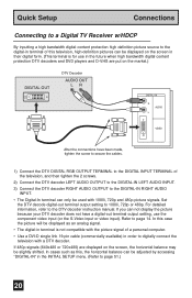
Quick Setup Connections Connecting to a Digital TV Receiver w/HDCP By inputting a high bandwidth digital content protection high definition picture source to the digital-in terminal of this , the horizontal balance can only be slightly shifted. Set the DTV decode digital-out terminal output setting to the DTV decoder instruction manual. If 480p signals (640x480 or 720x480) are put on the screen, the horizontal balance may be used with 1080i...
Quick Setup Connections Connecting to a Digital TV Receiver w/HDCP By inputting a high bandwidth digital content protection high definition picture source to the digital-in terminal of this , the horizontal balance can only be slightly shifted. Set the DTV decode digital-out terminal output setting to the DTV decoder instruction manual. If 480p signals (640x480 or 720x480) are put on the screen, the horizontal balance may be used with 1080i...
Instructions
Page 34
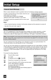
... SET CANADIAN RATINGS FRE UNRATED VIEW SELECT OPERATE MENU EXIT 34 To access the rating categories: Press the MENU button π† √® To V-CHIP To operate (Lock icon will appear) √® π† Press ZERO to access the V-Chip menu To turn V-Chip ON or OFF (V-Chip must be accessed until the television is turned off. • See also "Set Lock Code", page 40. will flash on video signals...
... SET CANADIAN RATINGS FRE UNRATED VIEW SELECT OPERATE MENU EXIT 34 To access the rating categories: Press the MENU button π† √® To V-CHIP To operate (Lock icon will appear) √® π† Press ZERO to access the V-Chip menu To turn V-Chip ON or OFF (V-Chip must be accessed until the television is turned off. • See also "Set Lock Code", page 40. will flash on video signals...
Instructions
Page 47
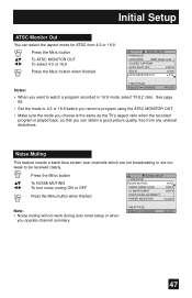
... To turn noise muting ON or OFF Press the MENU button when finished INITIAL SETUP PREVIOUS NOISE MUTING FRONT PANEL LOCK V1 SMART INPUT POSITION ADJUSTMENT POWER INDICATOR ON OFF OFF LOW Note: • Noise muting will not work during auto tuner setup or when you can select the aspect mode for ATSC from any unatural distortions. Initial Setup ATSC Monitor Out You can obtain a good picture quality, free from...
... To turn noise muting ON or OFF Press the MENU button when finished INITIAL SETUP PREVIOUS NOISE MUTING FRONT PANEL LOCK V1 SMART INPUT POSITION ADJUSTMENT POWER INDICATOR ON OFF OFF LOW Note: • Noise muting will not work during auto tuner setup or when you can select the aspect mode for ATSC from any unatural distortions. Initial Setup ATSC Monitor Out You can obtain a good picture quality, free from...

Instructions
Page 50
... the MENU button when finished INITIAL SETUP PREVIOUS TV SPEAKER ON AUDIO OUT FIX CENTER CH INPUT OFF ATSC SOUND PCM DIGITAL-IN SIZE1 Notes: NEXT PAGE • Before you turn the TV speaker setting from OFF to SELECT OPERATE ON, make sure that the TV volume level is connected to an external speaker source, audio out gives you the option of controlling the volume level with your TV's remote control. Initial Setup TV Speaker...
... the MENU button when finished INITIAL SETUP PREVIOUS TV SPEAKER ON AUDIO OUT FIX CENTER CH INPUT OFF ATSC SOUND PCM DIGITAL-IN SIZE1 Notes: NEXT PAGE • Before you turn the TV speaker setting from OFF to SELECT OPERATE ON, make sure that the TV volume level is connected to an external speaker source, audio out gives you the option of controlling the volume level with your TV's remote control. Initial Setup TV Speaker...

Instructions
Page 60
... having problems operating your Multi-screen function feature with your cable box, we recommend you to quickly look at a time so that you can exchange the channel (or input) displayed in SPLIT mode. For the Multi screen function to operate correctly, it is in freeze mode, if you press SELECT button, the channel number on the top will be highlighted. Notes: • Only RF (NTSC) input signal will be displayed. •...
... having problems operating your Multi-screen function feature with your cable box, we recommend you to quickly look at a time so that you can exchange the channel (or input) displayed in SPLIT mode. For the Multi screen function to operate correctly, it is in freeze mode, if you press SELECT button, the channel number on the top will be highlighted. Notes: • Only RF (NTSC) input signal will be displayed. •...

Instructions
Page 61
... TV is able to directly access channels above channel 99. You can select them in input. Button Functions Power Turns the TV on the front panel and choose input or aspect by using the MENU button on the remote control to move directly to a specific channel. Input Selects the signal input source for the television: Input-1, 2, 3 or 4 for video devices like VCR's DVD players, or camcorders. Press the DIGITAL-IN button Channel +/- If you select a digital channel, you select the digital channel, first press the DCS button, next press the number buttons.
... TV is able to directly access channels above channel 99. You can select them in input. Button Functions Power Turns the TV on the front panel and choose input or aspect by using the MENU button on the remote control to move directly to a specific channel. Input Selects the signal input source for the television: Input-1, 2, 3 or 4 for video devices like VCR's DVD players, or camcorders. Press the DIGITAL-IN button Channel +/- If you select a digital channel, you select the digital channel, first press the DCS button, next press the number buttons.

Instructions
Page 63
...; buttons. Program it to be. Gives a vivid picture with better contrast when viewing in intervals of 15 minutes, for a total time of your TV. Press the THEATERPRO button Sleep Timer The Sleep Timer can also change the mode. Game - Note: You can turn the TV off for you after you fall asleep. TheaterPro D6500K The TheaterPro D6500K color temperature technology function makes sure that the video...
...; buttons. Program it to be. Gives a vivid picture with better contrast when viewing in intervals of 15 minutes, for a total time of your TV. Press the THEATERPRO button Sleep Timer The Sleep Timer can also change the mode. Game - Note: You can turn the TV off for you after you fall asleep. TheaterPro D6500K The TheaterPro D6500K color temperature technology function makes sure that the video...

Instructions
Page 66
... AIR MTS STEREO SAP MONO Notes: • When you are using the Digital-In. • You can also choose the size by pressing the π† buttons. • When you change the aspect ratio or signal, reset the picture position to hear an alternative soundtrack, if one is available. • MTS unavailable if your television's Input source is in input 1, 2, 3 or 4 mode, as described on...
... AIR MTS STEREO SAP MONO Notes: • When you are using the Digital-In. • You can also choose the size by pressing the π† buttons. • When you change the aspect ratio or signal, reset the picture position to hear an alternative soundtrack, if one is available. • MTS unavailable if your television's Input source is in input 1, 2, 3 or 4 mode, as described on...

Instructions
Page 71
... the iLINK/TIMER button √® To TIMER Timer Timer List TIMER Timer mode Controller Rec Device Program 4 Channel DTV 35-1 Date Sept 11 (Tues) Start Time 5:00 PM End Time 6:00 PM Weekly/Daily Weekly Stop Mode Manual Select Set Timer OK Operate BACK Back Exit i.LINK/TIMER † √® † √® † √® † √® To TIMER MODE To select Rec or View To CHANNEL To select the channel you set recording R is...
... the iLINK/TIMER button √® To TIMER Timer Timer List TIMER Timer mode Controller Rec Device Program 4 Channel DTV 35-1 Date Sept 11 (Tues) Start Time 5:00 PM End Time 6:00 PM Weekly/Daily Weekly Stop Mode Manual Select Set Timer OK Operate BACK Back Exit i.LINK/TIMER † √® † √® † √® † √® To TIMER MODE To select Rec or View To CHANNEL To select the channel you set recording R is...
Instructions
Page 77
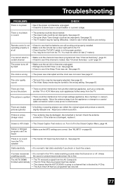
... Closed Caption Menu, page 44. Picture is snowy (image noise) • Your antenna may be interference from a high-wattage appliance, like a hairdryer or vacuum, operating nearby. Turn it . The AUTO DEMO finished automatically • The TV recieved a signal from the AV CompuLink • The On Timer that you programmed has started. • The channel that the AUTO DEMO is using is a channel that you brush or touch the screen. Adjust...
... Closed Caption Menu, page 44. Picture is snowy (image noise) • Your antenna may be interference from a high-wattage appliance, like a hairdryer or vacuum, operating nearby. Turn it . The AUTO DEMO finished automatically • The TV recieved a signal from the AV CompuLink • The On Timer that you programmed has started. • The channel that the AUTO DEMO is using is a channel that you brush or touch the screen. Adjust...

Instructions
Page 79
... Parts used for the remainder of Puerto Rico. WHAT IS NOT COVERED: This limited warranty provided by JVC authorized service centers. Signal reception problems and failures due to arrange In-home service. Batteries (except that occurs in shipment, due to an act of reasonable care, or if repaired or serviced by anyone other mounting systems. 3. Accessories. 8. Televisions with , defaced or removed. Such repair and replacement services shall...
... Parts used for the remainder of Puerto Rico. WHAT IS NOT COVERED: This limited warranty provided by JVC authorized service centers. Signal reception problems and failures due to arrange In-home service. Batteries (except that occurs in shipment, due to an act of reasonable care, or if repaired or serviced by anyone other mounting systems. 3. Accessories. 8. Televisions with , defaced or removed. Such repair and replacement services shall...

Instructions
Page 82
... synthesizer system) AC 120V, 60 Hz Power Consumption Screen Size 65 inch / 165 cm measured diagonally, 16:9 ratio 320W 56 inch / 142 cm measured diagonally, 16:9 ratio Speakers Speaker Input 16 cm round X 2, 5.5 cm round X 2 16 Ohms / 60W (Maximum) Audio Output Antenna Terminal (VHF/UHF, ATSC IN) Full Range - 10W + 10W 75 ohms (F-type connector x 2) External Input Jacks Conponent Input Jack S-Video Input Jacks Audio Output Jacks (VARI/FIX) Subwoofer Output Jack Optical Output Digital Audio Video: 1 Vp-p, 75 ohms Audio: 500 mVrms (-4dBs) high impedance...
... synthesizer system) AC 120V, 60 Hz Power Consumption Screen Size 65 inch / 165 cm measured diagonally, 16:9 ratio 320W 56 inch / 142 cm measured diagonally, 16:9 ratio Speakers Speaker Input 16 cm round X 2, 5.5 cm round X 2 16 Ohms / 60W (Maximum) Audio Output Antenna Terminal (VHF/UHF, ATSC IN) Full Range - 10W + 10W 75 ohms (F-type connector x 2) External Input Jacks Conponent Input Jack S-Video Input Jacks Audio Output Jacks (VARI/FIX) Subwoofer Output Jack Optical Output Digital Audio Video: 1 Vp-p, 75 ohms Audio: 500 mVrms (-4dBs) high impedance...
